


Filter by
Material
Maximum Pressure @ Temperature
Specifications Met
RoHS
DFARS Specialty Metals
Gauge Siphon Tubes
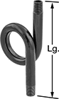 | 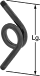 | 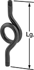 | 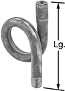 |
Style A | Style B | Style C | Style D |
Also known as pigtails, these siphon tubes protect dry gauges from steam and high-temperature fluids. Add water to the tube to create a protective barrier between your gauge and process media.
NPT Male Connections
|
Style A |
|
Style B |
|
Style C |
Style C—Style C requires less maintenance than Styles A, B, and D because the extra bends prolong water retention.
Style | Pipe Size | Lg. | Max. Pressure @ Temp. | Specs. Met | Each | ||||||||||||||||||||||||||||||||||||||||||||||||||||||||||||||||||||||||||||||||||||||||||||||
|---|---|---|---|---|---|---|---|---|---|---|---|---|---|---|---|---|---|---|---|---|---|---|---|---|---|---|---|---|---|---|---|---|---|---|---|---|---|---|---|---|---|---|---|---|---|---|---|---|---|---|---|---|---|---|---|---|---|---|---|---|---|---|---|---|---|---|---|---|---|---|---|---|---|---|---|---|---|---|---|---|---|---|---|---|---|---|---|---|---|---|---|---|---|---|---|---|---|---|---|
Brass | |||||||||||||||||||||||||||||||||||||||||||||||||||||||||||||||||||||||||||||||||||||||||||||||||||
| A | 1/4 | 4" | 240 psi @ 400° F | ASTM B43 | 4031K28 | 000000 | |||||||||||||||||||||||||||||||||||||||||||||||||||||||||||||||||||||||||||||||||||||||||||||
| A | 1/4 | 4" | 1,000 psi @ 400° F | ASTM B43 | 4031K68 | 00000 | |||||||||||||||||||||||||||||||||||||||||||||||||||||||||||||||||||||||||||||||||||||||||||||
| A | 1/4 | 5 5/8" | 240 psi @ 400° F | ASTM B43 | 4031K65 | 00000 | |||||||||||||||||||||||||||||||||||||||||||||||||||||||||||||||||||||||||||||||||||||||||||||
| A | 1/4 | 5 5/8" | 1,000 psi @ 400° F | ASTM B43 | 4031K61 | 00000 | |||||||||||||||||||||||||||||||||||||||||||||||||||||||||||||||||||||||||||||||||||||||||||||
| B | 1/4 | 6 1/2" | 240 psi @ 400° F | ASTM B43 | 4031K66 | 00000 | |||||||||||||||||||||||||||||||||||||||||||||||||||||||||||||||||||||||||||||||||||||||||||||
| B | 1/4 | 6 1/2" | 1,000 psi @ 400° F | ASTM B43 | 4031K63 | 00000 | |||||||||||||||||||||||||||||||||||||||||||||||||||||||||||||||||||||||||||||||||||||||||||||
| C | 1/4 | 7 1/2" | 240 psi @ 400° F | ASTM B43 | 4031K67 | 00000 | |||||||||||||||||||||||||||||||||||||||||||||||||||||||||||||||||||||||||||||||||||||||||||||
| C | 1/4 | 7 1/2" | 1,000 psi @ 400° F | ASTM B43 | 4031K64 | 00000 | |||||||||||||||||||||||||||||||||||||||||||||||||||||||||||||||||||||||||||||||||||||||||||||
304 Stainless Steel | |||||||||||||||||||||||||||||||||||||||||||||||||||||||||||||||||||||||||||||||||||||||||||||||||||
| A | 1/4 | 5 1/2" | 1,500 psi @ 700° F | ASTM A312 | 4031K26 | 00000 | |||||||||||||||||||||||||||||||||||||||||||||||||||||||||||||||||||||||||||||||||||||||||||||
| A | 1/4 | 5 1/2" | 440 psi @ 750° F | ASTM A312 | 4031K71 | 00000 | |||||||||||||||||||||||||||||||||||||||||||||||||||||||||||||||||||||||||||||||||||||||||||||
316 Stainless Steel | |||||||||||||||||||||||||||||||||||||||||||||||||||||||||||||||||||||||||||||||||||||||||||||||||||
| A | 1/4 | 5 1/2" | 450 psi @ 750° F | ASTM A312 | 4965K35 | 00000 | |||||||||||||||||||||||||||||||||||||||||||||||||||||||||||||||||||||||||||||||||||||||||||||
| A | 1/2 | 8 7/8" | 730 psi @ 800° F | ASTM A312 | 4965K36 | 000000 | |||||||||||||||||||||||||||||||||||||||||||||||||||||||||||||||||||||||||||||||||||||||||||||
| A | 1/2 | 8 7/8" | 1,500 psi @ 800° F | ASTM A312 | 4965K67 | 000000 | |||||||||||||||||||||||||||||||||||||||||||||||||||||||||||||||||||||||||||||||||||||||||||||
| B | 1/4 | 6 1/2" | 450 psi @ 750° F | ASTM A312 | 4965K37 | 00000 | |||||||||||||||||||||||||||||||||||||||||||||||||||||||||||||||||||||||||||||||||||||||||||||
| B | 1/2 | 10" | 730 psi @ 800° F | ASTM A312 | 4965K38 | 000000 | |||||||||||||||||||||||||||||||||||||||||||||||||||||||||||||||||||||||||||||||||||||||||||||
| C | 1/4 | 7 1/4" | 450 psi @ 750° F | ASTM A312 | 4965K39 | 00000 | |||||||||||||||||||||||||||||||||||||||||||||||||||||||||||||||||||||||||||||||||||||||||||||
| C | 1/2 | 12" | 730 psi @ 800° F | ASTM A312 | 4965K42 | 000000 | |||||||||||||||||||||||||||||||||||||||||||||||||||||||||||||||||||||||||||||||||||||||||||||
Seamless Steel | |||||||||||||||||||||||||||||||||||||||||||||||||||||||||||||||||||||||||||||||||||||||||||||||||||
| A | 1/4 | 5 1/2" | 580 psi @ 750° F | ASTM A106 Grade B | 4031K21 | 00000 | |||||||||||||||||||||||||||||||||||||||||||||||||||||||||||||||||||||||||||||||||||||||||||||
| A | 1/4 | 5 1/2" | 2,000 psi @ 750° F | ASTM A106 Grade B | 4031K51 | 00000 | |||||||||||||||||||||||||||||||||||||||||||||||||||||||||||||||||||||||||||||||||||||||||||||
| A | 1/2 | 8 7/8" | 1,000 psi @ 700° F | ASTM A106 Grade B | 4031K82 | 00000 | |||||||||||||||||||||||||||||||||||||||||||||||||||||||||||||||||||||||||||||||||||||||||||||
| A | 1/2 | 8 7/8" | 1,700 psi @ 800° F | ASTM A106 Grade B | 4031K83 | 00000 | |||||||||||||||||||||||||||||||||||||||||||||||||||||||||||||||||||||||||||||||||||||||||||||
| B | 1/4 | 6 1/2" | 580 psi @ 750° F | ASTM A106 Grade B | 4031K23 | 00000 | |||||||||||||||||||||||||||||||||||||||||||||||||||||||||||||||||||||||||||||||||||||||||||||
| B | 1/4 | 6 1/2" | 2,000 psi @ 750° F | ASTM A106 Grade B | 4031K53 | 00000 | |||||||||||||||||||||||||||||||||||||||||||||||||||||||||||||||||||||||||||||||||||||||||||||
| C | 1/4 | 7 1/4" | 580 psi @ 750° F | ASTM A106 Grade B | 4031K24 | 00000 | |||||||||||||||||||||||||||||||||||||||||||||||||||||||||||||||||||||||||||||||||||||||||||||
| C | 1/4 | 7 1/4" | 2,000 psi @ 750° F | ASTM A106 Grade B | 4031K54 | 00000 | |||||||||||||||||||||||||||||||||||||||||||||||||||||||||||||||||||||||||||||||||||||||||||||
Welded Steel | |||||||||||||||||||||||||||||||||||||||||||||||||||||||||||||||||||||||||||||||||||||||||||||||||||
| A | 1/4 | 5 1/2" | 300 psi @ 400° F | ASTM A53 Type F | 4031K11 | 00000 | |||||||||||||||||||||||||||||||||||||||||||||||||||||||||||||||||||||||||||||||||||||||||||||
| A | 1/4 | 5 1/2" | 1,000 psi @ 400° F | ASTM A53 Type F | 4031K41 | 00000 | |||||||||||||||||||||||||||||||||||||||||||||||||||||||||||||||||||||||||||||||||||||||||||||
| A | 1/2 | 8 7/8" | 1,000 psi @ 400° F | ASTM A53 Type F | 4031K81 | 00000 | |||||||||||||||||||||||||||||||||||||||||||||||||||||||||||||||||||||||||||||||||||||||||||||
| B | 1/4 | 6 1/2" | 300 psi @ 400° F | ASTM A53 Type F | 4031K13 | 00000 | |||||||||||||||||||||||||||||||||||||||||||||||||||||||||||||||||||||||||||||||||||||||||||||
| B | 1/4 | 6 1/2" | 1,000 psi @ 400° F | ASTM A53 Type F | 4031K43 | 00000 | |||||||||||||||||||||||||||||||||||||||||||||||||||||||||||||||||||||||||||||||||||||||||||||
| C | 1/4 | 7 1/4" | 300 psi @ 400° F | ASTM A53 Type F | 4031K14 | 00000 | |||||||||||||||||||||||||||||||||||||||||||||||||||||||||||||||||||||||||||||||||||||||||||||
| C | 1/4 | 7 1/4" | 1,000 psi @ 400° F | ASTM A53 Type F | 4031K44 | 00000 | |||||||||||||||||||||||||||||||||||||||||||||||||||||||||||||||||||||||||||||||||||||||||||||
