


Filter by
For Use With
Outlet Pressure
Maximum Pressure
Body Material
Maximum Inlet Pressure
Maximum Pressure Regulation
Inlet Thread Type
Valve Function
Display Type

Maximum Temperature
DFARS Specialty Metals
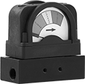
Low-Pressure Differential Gauges with Color Indicator
Glass-Filled Nylon Case with Anodized Aluminum Connections (Pounds per Square Inch)
 |
Pressure Range, psi | |||||||||||||||
|---|---|---|---|---|---|---|---|---|---|---|---|---|---|---|---|
Green Band | Yellow Band | Red Band | Max. Pressure, psi | Environment Temp. Range, ° F | Process Temp. Range, ° F | Ht. | Wd. | Dp. | Case Color | For Use With | Accuracy | Each | |||
1/4 NPT Female Threaded Pipe Connection | |||||||||||||||
| 0 to 13 | 13 to 20 | 20 to 30 | 300 | -40 to 200 | -40 to 200 | 3 1/4" | 3 1/4" | 1 1/2" | Black | Air, Water, Hydraulic Fluid, Carbon Dioxide, Nitrogen, Hydrogen, Argon, Acetylene | ±5% | 2238K27 | 0000000 | ||
Low-Pressure-Regulating Valves for Water
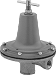 |
Designed for excellent performance at low pressures, these valves respond to even the slightest inlet pressure changes to maintain a lower, stable outlet pressure. Adjust the outlet pressure within the range. Valves have an internal strainer to trap debris.
Inlet | Outlet | ||||||||||||
|---|---|---|---|---|---|---|---|---|---|---|---|---|---|
Pipe Size | Location | Max. Pressure, psi | Pipe Size | Location | Pressure Adjustment Method | End-to-End Lg. | For Use With | Temp. Range, ° F | Outlet Pressure, psi | Each | |||
NPT Female | |||||||||||||
Brass Body—Buna-N-Coated Nylon Diaphragm and 303 Stainless Steel Seal with Internal Strainer | |||||||||||||
| 1/4 | Side | 300 | 1/4 | Side | T-Handle | 4 1/4" | Water | 0 to 120 | 0 to 20 | 3878T41 | 0000000 | ||
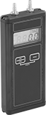
Differential Pressure and Vacuum Gauges with Digital Display
Aluminum Case with Brass Connection—(psi, kPa, in. of H₂O, in. of Hg, mbar)
 |
Pressure Range | Vacuum Range, in. Hg | Pressure Resolution, in. H₂O | Max. Pressure | For Tube ID | Environment Temp. Range, ° F | Process Temp. Range, ° F | Digit Ht. | Batteries Included | Features | For Use With | Accuracy | Each | |||
|---|---|---|---|---|---|---|---|---|---|---|---|---|---|---|---|
Barbed Fitting Connection | |||||||||||||||
| 0 psi to 20 psi 0 psi to 60 psi 0 kPa to 137.9 kPa 0 in. H₂O to 553 in. H₂O 0 mbar to 1,379 mbar | 0 to 40.72 | 0.01 | 20 psi; 60 psi; 137.9 kPa; 553 in. H₂O; 1,379 mbar | 1/8" to 3/16" | 35 to 100 | 0 to 140 | 3/8" | Yes | 40-Reading Memory, Overpressure Alarm | Air | ±0.5% Full-Scale Accuracy (Not Rated) | 4125K46 | 0000000 | ||
Barbed Fitting Connection with Calibration Certificate Traceable to NIST | |||||||||||||||
| 0 psi to 20 psi 0 psi to 60 psi 0 kPa to 137.9 kPa 0 in. H₂O to 553 in. H₂O 0 mbar to 1,379 mbar | 0 to 40.72 | 0.01 | 20 psi; 60 psi; 137.9 kPa; 553 in. H₂O; 1,379 mbar | 1/8" to 3/16" | 35 to 100 | 0 to 140 | 3/8" | Yes | 40-Reading Memory, Overpressure Alarm | Air | ±0.5% Full-Scale Accuracy (Not Rated) | 4125K66 | 000000 | ||
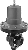
High-Accuracy Pressure-Regulating Valves for Steam
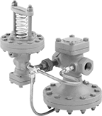 |
Control steam line pressure with ±1 psi accuracy. These valves automatically reduce a high, variable inlet pressure to a lower, stable outlet pressure. Adjust the outlet pressure within the range. Valves have a cast iron body that absorbs vibration from pressure changes to reduce wear and noise in your pipeline. They meet ANSI/FCI 70-2 Class IV for tight shut-off (max. leakage rate of 0.01%). Install 1/4 NPT male pipe (not included) between the control valve and your downstream steam line.
Repair Kits—Repair kits (sold separately) include replacement seals, diaphragm, spring, and spring assembly.
Valves | Repair Kits | ||||||||||||||
|---|---|---|---|---|---|---|---|---|---|---|---|---|---|---|---|
Inlet | Outlet | ||||||||||||||
Pipe Size | Location | Max. Pressure, psi | Pipe Size | Location | Pressure Adjustment Method | For Use With | Temp. Range, ° F | Specs. Met | Outlet Pressure, psi | Each | Each | ||||
NPT Female | |||||||||||||||
Cast Iron Body—301 Stainless Steel Diaphragm and 420 Stainless Steel Seal | |||||||||||||||
| 1/2 | Side | 250 | 1/2 | Side | Screw | Steam | 40 to 450 | ANSI/FCI 70-2 Class IV | 3 to 20 | 9792K19 | 000000000 | 9792K32 | 0000000 | ||
| 3/4 | Side | 250 | 3/4 | Side | Screw | Steam | 40 to 450 | ANSI/FCI 70-2 Class IV | 3 to 20 | 9792K21 | 00000000 | 9792K33 | 000000 | ||
| 1 | Side | 250 | 1 | Side | Screw | Steam | 40 to 450 | ANSI/FCI 70-2 Class IV | 3 to 20 | 9792K23 | 00000000 | 9792K34 | 000000 | ||
| 1 1/4 | Side | 250 | 1 1/4 | Side | Screw | Steam | 40 to 450 | ANSI/FCI 70-2 Class IV | 3 to 20 | 9792K25 | 00000000 | 9792K35 | 000000 | ||
| 1 1/2 | Side | 250 | 1 1/2 | Side | Screw | Steam | 40 to 450 | ANSI/FCI 70-2 Class IV | 3 to 20 | 9792K27 | 00000000 | 9792K36 | 000000 | ||
| 2 | Side | 250 | 2 | Side | Screw | Steam | 40 to 450 | ANSI/FCI 70-2 Class IV | 3 to 20 | 9792K29 | 00000000 | 9792K37 | 00000000 | ||
High-Pressure Differential Gauges
Aluminum Case with Aluminum Connections—Single Scale (Pounds per Square Inch)
 |
Dial Dia. | Max. Pressure, psi | Environment Temp. Range, ° F | Process Temp. Range, ° F | For Use With | Accuracy | Pressure, psi | Graduations, psi | Pressure Numeric Increments, psi | Each | |||
|---|---|---|---|---|---|---|---|---|---|---|---|---|
1/4 NPT Female Threaded Pipe Connection | ||||||||||||
| 2 1/2" | 3,000 | 0 to 150 | 0 to 200 | Water, Hydraulic Fluid, Gasoline | ±2% | 0 to 20 | 1 | 5 | 4107K117 | 0000000 | ||
| 4 1/2" | 3,000 | 0 to 150 | 0 to 200 | Water, Hydraulic Fluid, Gasoline | ±2% | 0 to 20 | 1 | 5 | 4107K513 | 000000 | ||
316 Stainless Steel Case with 316 Stainless Steel Connections—Single Scale (Pounds per Square Inch)
|
Gauges with 316 stainless steel case are more corrosion resistant than gauges with an aluminum case.
Dial Dia. | Max. Pressure, psi | Environment Temp. Range, ° F | Process Temp. Range, ° F | For Use With | Accuracy | Pressure, psi | Graduations, psi | Pressure Numeric Increments, psi | Each | |||
|---|---|---|---|---|---|---|---|---|---|---|---|---|
1/4 NPT Female Threaded Pipe Connection | ||||||||||||
| 2 1/2" | 3,000 | 0 to 150 | 0 to 200 | Water, Hydraulic Fluid, Gasoline | ±2% | 0 to 20 | 1 | 5 | 4232K113 | 0000000 | ||
| 4 1/2" | 3,000 | 0 to 150 | 0 to 200 | Water, Hydraulic Fluid, Gasoline | ±2% | 0 to 20 | 1 | 5 | 4232K513 | 000000 | ||
Vibration-Damping Pressure-Regulating Valves for Water, Oil, Air, and Inert Gas
 |
A cast iron body absorbs vibration from pressure changes to reduce wear and noise in your pipeline. These valves automatically reduce a high, variable inlet pressure to a lower, stable outlet pressure. Adjust the outlet pressure within the range.
Internal Strainer—Internal strainers trap debris.
Inlet | Outlet | ||||||||||||
|---|---|---|---|---|---|---|---|---|---|---|---|---|---|
Pipe Size | Location | Max. Pressure, psi | Pipe Size | Location | Pressure Adjustment Method | End-to-End Lg. | For Use With | Temp. Range, ° F | Outlet Pressure, psi | Each | |||
NPT Female | |||||||||||||
Cast Iron Body—Buna-N Diaphragm and Seal with Internal Strainer | |||||||||||||
| 3/4 | Side | 200 | 3/4 | Side | Screw | 5 1/8" | Water, Oil, Air, Inert Gas | 32 to 180 | 2 to 20 | 4674K44 | 0000000 | ||
| 1 | Side | 200 | 1 | Side | Screw | 5 7/8" | Water, Oil, Air, Inert Gas | 32 to 180 | 2 to 20 | 4674K45 | 000000 | ||
| 2 | Side | 200 | 2 | Side | Screw | 9 1/4" | Water, Oil, Air, Inert Gas | 32 to 180 | 2 to 20 | 4674K48 | 00000000 | ||
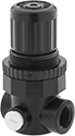
Manifold-Mount Compressed Air Regulators
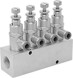 |
Multiple Regulators Shown Installed (Manifold Sold Separately) |
Mount these miniature regulators on a manifold (sold separately) to create a regulating manifold. Each regulator can be set to a different output pressure, so you can power multiple tools or machines with a single air supply. All are relieving regulators, so they exhaust when the downstream pressure exceeds the set pressure. Install them in your air line after filters.
NPT Male Inlet × UNF Threaded Female Outlet
Panel-Mount Nut—Regulators with a panel-mount nut can be installed through a hole in a panel or enclosure. They let you hide your air lines without losing access to the control knob.
Regulators | 4-Outlet Manifolds | 6-Outlet Manifolds | 10-Outlet Manifolds | |||||||||||||||||
|---|---|---|---|---|---|---|---|---|---|---|---|---|---|---|---|---|---|---|---|---|
Overall | ||||||||||||||||||||
Inlet Pipe Size | Outlet Thread Size | Max. Flow Rate @ Pressure | Max. Pressure, psi | Housing Material | Gauge Included | Wd. | Ht. | Max. Temp., ° F | Includes | Regulating Accuracy | Pressure Regulation, psi | Each | Each | Each | Each | |||||
| 1/8 | 10-32 | 5 scfm @ 100 psi | 250 | Brass | No | 3/4" | 2 3/4" | 150 | Panel-Mount Nut | ±10% | 0 to 20 | 41795K4 | 000000 | 5469K121 | 000000 | 5469K151 | 000000 | 5469K191 | 000000 | |
Tire Gauges with Indicator Bar
1 Angled Head
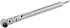 |
Stainless Steel—Stainless steel gauges are more corrosion resistant than steel and brass gauges.
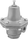
High-Temperature Pressure-Regulating Valves for Water, Oil, Air, and Inert Gas
 |
Rated for more than double the temperature of standard pressure-regulating valves, these can withstand temperatures up to 550° F. They automatically reduce a high, variable inlet pressure to a lower, stable outlet pressure. Adjust the outlet pressure within the range. Valves meet ANSI/FCI 70-2 Class IV for tight shut-off (max. leakage rate of 0.01%).
Inlet | Outlet | |||||||||||||
|---|---|---|---|---|---|---|---|---|---|---|---|---|---|---|
Pipe Size | Location | Max. Pressure, psi | Pipe Size | Location | Pressure Adjustment Method | End-to-End Lg. | For Use With | Temp. Range, ° F | Specs. Met | Outlet Pressure, psi | Each | |||
NPT Female | ||||||||||||||
Steel Body—316 Stainless Steel Diaphragm and 303 Stainless Steel Seal | ||||||||||||||
| 1 | Side | 300 | 1 | Side | Screw | 4 3/16" | Water, Oil, Air, Inert Gas | 32 to 550 | ANSI/FCI 70-2 Class IV | 5 to 20 | 46395K25 | 000000000 | ||
| 1 1/2 | Side | 300 | 1 1/2 | Side | Screw | 4 13/16" | Water, Oil, Air, Inert Gas | 32 to 550 | ANSI/FCI 70-2 Class IV | 5 to 20 | 46395K27 | 00000000 | ||
| 2 | Side | 300 | 2 | Side | Screw | 5 1/2" | Water, Oil, Air, Inert Gas | 32 to 550 | ANSI/FCI 70-2 Class IV | 5 to 20 | 46395K29 | 00000000 | ||
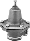
Long-Life Pressure-Regulating Valves for Steam
 |
For a longer service life than cast iron valves, these have a durable bronze body. All automatically reduce a high, variable inlet pressure to a lower, stable outlet pressure. Adjust the outlet pressure within the range. Valves have an internal strainer to trap debris.
Inlet | Outlet | ||||||||||||
|---|---|---|---|---|---|---|---|---|---|---|---|---|---|
Pipe Size | Location | Max. Pressure, psi | Pipe Size | Location | Pressure Adjustment Method | End-to-End Lg. | For Use With | Temp. Range, ° F | Outlet Pressure, psi | Each | |||
NPT Female | |||||||||||||
Bronze Body—Bronze Diaphragm and PTFE Seal with Internal Strainer | |||||||||||||
| 3/4 | Side | 250 | 3/4 | Side | Screw | 5 1/8" | Steam | -20 to 400 | 2 to 20 | 47345K34 | 0000000 | ||
| 1 | Side | 250 | 1 | Side | Screw | 5 7/8" | Steam | -20 to 400 | 2 to 20 | 47345K35 | 000000 | ||
| 2 | Side | 250 | 2 | Side | Screw | 9 1/4" | Steam | -20 to 400 | 2 to 20 | 47345K38 | 00000000 | ||
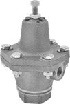
Corrosion-Resistant Pressure-Regulating Valves for Water, Oil, Air, and Inert Gas
 |
Often used in wet conditions and harsh environments, these valves have a 316 stainless steel body for excellent corrosion resistance. They automatically reduce a high, variable inlet pressure to a lower, stable outlet pressure. Adjust the outlet pressure within the range.
Inlet | Outlet | ||||||||||||
|---|---|---|---|---|---|---|---|---|---|---|---|---|---|
Pipe Size | Location | Max. Pressure, psi | Pipe Size | Location | Pressure Adjustment Method | End-to-End Lg. | For Use With | Temp. Range, ° F | Outlet Pressure, psi | Each | |||
NPT Female | |||||||||||||
316 Stainless Steel Body—Buna-N Diaphragm and Seal | |||||||||||||
| 3/4 | Side | 720 | 3/4 | Side | Screw | 5 1/8" | Water, Oil, Air, Inert Gas | 32 to 200 | 2 to 20 | 8099K21 | 000000000 | ||
| 1 | Side | 720 | 1 | Side | Screw | 5 7/8" | Water, Oil, Air, Inert Gas | 32 to 200 | 2 to 20 | 8099K31 | 00000000 | ||
Pressure Recording Film
Pressure Film
 |  |
Impression Record Before Analysis |
Pressure Range, psi | Image Produced | Temp. Range, ° F | Includes | Accuracy | Each | |||
|---|---|---|---|---|---|---|---|---|
11" × 17" | ||||||||
0.02" Thick | ||||||||
| 2 to 20 | Grayscale | 0 to 150 | Two 0.01" Thick Sheets | Not Rated | 3145K22 | 000000 | ||
Long-Life Pressure-Regulating Valves for Water, Oil, Air, and Inert Gas
 |
For a longer service life than brass and cast iron valves, these have a durable bronze body. They automatically reduce a high, variable inlet pressure to a lower, stable outlet pressure. Adjust the outlet pressure within the range. All valves have an internal strainer to trap debris.
Inlet | Outlet | ||||||||||||
|---|---|---|---|---|---|---|---|---|---|---|---|---|---|
Pipe Size | Location | Max. Pressure, psi | Pipe Size | Location | Pressure Adjustment Method | End-to-End Lg. | For Use With | Temp. Range, ° F | Outlet Pressure, psi | Each | |||
NPT Female | |||||||||||||
Bronze Body—Buna-N Diaphragm and Seal with Internal Strainer | |||||||||||||
| 3/4 | Side | 400 | 3/4 | Side | Screw | 5 1/8" | Water, Oil, Air, Inert Gas | 32 to 180 | 2 to 20 | 47345K14 | 0000000 | ||
| 1 | Side | 400 | 1 | Side | Screw | 5 7/8" | Water, Oil, Air, Inert Gas | 32 to 180 | 2 to 20 | 47345K15 | 000000 | ||
| 2 | Side | 400 | 2 | Side | Screw | 9 1/4" | Water, Oil, Air, Inert Gas | 32 to 180 | 2 to 20 | 47345K18 | 00000000 | ||
Pressure-Regulating Valves for Steam
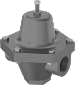 |
Automatically reduce a high, variable inlet pressure in your steam system to a lower, stable outlet pressure. Adjust the outlet pressure within the range. These valves have a cast iron body that absorbs vibration from pressure changes to reduce wear and noise in your pipeline.
Internal Strainer—Internal strainers trap debris.
Valves | Repair Kits | ||||||||||||||
|---|---|---|---|---|---|---|---|---|---|---|---|---|---|---|---|
Inlet | Outlet | ||||||||||||||
Pipe Size | Location | Max. Pressure, psi | Pipe Size | Location | Pressure Adjustment Method | End-to-End Lg. | For Use With | Temp. Range, ° F | Outlet Pressure, psi | Each | Each | ||||
NPT Female | |||||||||||||||
Cast Iron Body—Bronze Diaphragm and PTFE Seal with Internal Strainer | |||||||||||||||
| 3/4 | Side | 150 | 3/4 | Side | Screw | 5 1/8" | Steam | -20 to 400 | 2 to 20 | 4674K64 | 0000000 | 4674K92 | 0000000 | ||
| 1 | Side | 150 | 1 | Side | Screw | 5 7/8" | Steam | -20 to 400 | 2 to 20 | 4674K65 | 000000 | 4674K93 | 000000 | ||
| 2 | Side | 150 | 2 | Side | Screw | 9 1/4" | Steam | -20 to 400 | 2 to 20 | 4674K68 | 00000000 | 4674K95 | 000000 | ||
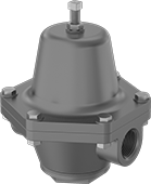
Compact Compressed Air Regulators
Relieving with Gauge Not Included
 |
Relieving regulators exhaust when the downstream pressure exceeds the set pressure.
Mounting Brackets—Mounting brackets (sold separately) allow you to attach the regulator to a wall or equipment.
Regulators | Mounting Brackets | |||||||||||||||
|---|---|---|---|---|---|---|---|---|---|---|---|---|---|---|---|---|
Pipe Size | Overall | |||||||||||||||
Inlet | Outlet | Max. Flow Rate @ Pressure | Max. Pressure, psi | Housing Material | No. of Gauge Ports | Wd. | Ht. | Max. Temp., ° F | Regulating Accuracy | Pressure Regulation, psi | Each | Each | ||||
NPT Female Inlet × NPT Female Outlet | ||||||||||||||||
| 1/8 | 1/8 | 25 scfm @ 100 psi | 250 | Nylon | 2 | 1 1/2" | 2 3/4" | 120 | ±3 psi | 3 to 20 | 6746K28 | 000000 | 6746K83 | 00000 | ||
| 1/4 | 1/4 | 25 scfm @ 100 psi | 250 | Nylon | 2 | 1 1/2" | 2 3/4" | 120 | ±3 psi | 3 to 20 | 6746K29 | 00000 | 6746K83 | 0000 | ||
Relieving with Gauge Included
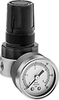 |
Relieving regulators exhaust when the downstream pressure exceeds the set pressure.
Mounting Brackets—Mounting brackets (sold separately) allow you to attach the regulator to a wall or equipment.
Regulators | Mounting Brackets | ||||||||||||||
|---|---|---|---|---|---|---|---|---|---|---|---|---|---|---|---|
Pipe Size | Overall | ||||||||||||||
Inlet | Outlet | Max. Flow Rate @ Pressure | Max. Pressure, psi | Housing Material | Wd. | Ht. | Max. Temp., ° F | Regulating Accuracy | Pressure Regulation, psi | Each | Each | ||||
NPT Female Inlet × NPT Female Outlet | |||||||||||||||
| 1/8 | 1/8 | 25 scfm @ 100 psi | 250 | Nylon | 1 1/2" | 2 3/4" | 120 | ±3 psi | 3 to 20 | 6746K38 | 000000 | 6746K83 | 00000 | ||
| 1/4 | 1/4 | 25 scfm @ 100 psi | 250 | Nylon | 1 1/2" | 2 3/4" | 120 | ±3 psi | 3 to 20 | 6746K39 | 00000 | 6746K83 | 0000 | ||
Differential Pressure Transmitters for Liquids
Steel Housing
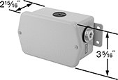 |
IP56 Enclosure Rating—IP56 rated transmitters protect against some dust and washdowns.
NEMA 4 Enclosure Rating—NEMA 4 rated transmitters protect against weather and washdowns.
Mounting Holes | Connection | |||||||||||||||||||
|---|---|---|---|---|---|---|---|---|---|---|---|---|---|---|---|---|---|---|---|---|
Pressure Differential | Max. Input Pressure, psi | Input Voltage, V DC | Pipe Size | For No. of Wires | Mounting Hardware Included | Dia. | No. of | Ht. | Wd. | Enclosure Rating | For Use With | Accuracy | Pipe | Fitting | Material | Temp. Range, ° F | Each | |||
4 to 20 mA Output Signal—Screw Terminals | ||||||||||||||||||||
| 0 in. H₂O to 1 in. H₂O | 20 | 18 to 30 | 1/8 | 2 | No | 7/32" | 4 | 3 5/16" | 2 15/16" | IP56, NEMA 4 | Hydraulic Fluid, Water | ±1% | NPT Female | Threaded | Brass | 32 to 122 | 5842N11 | 000000000 | ||
| 0 in. H₂O to 3 in. H₂O | 20 | 18 to 30 | 1/8 | 2 | No | 7/32" | 4 | 3 5/16" | 2 15/16" | IP56, NEMA 4 | Hydraulic Fluid, Water | ±1% | NPT Female | Threaded | Brass | 32 to 122 | 5842N12 | 000000 | ||
| 0 in. H₂O to 5 in. H₂O | 20 | 18 to 30 | 1/8 | 2 | No | 7/32" | 4 | 3 5/16" | 2 15/16" | IP56, NEMA 4 | Hydraulic Fluid, Water | ±1% | NPT Female | Threaded | Brass | 32 to 122 | 5842N13 | 000000 | ||
| 0 in. H₂O to 10 in. H₂O | 20 | 18 to 30 | 1/8 | 2 | No | 7/32" | 4 | 3 5/16" | 2 15/16" | IP56, NEMA 4 | Hydraulic Fluid, Water | ±1% | NPT Female | Threaded | Brass | 32 to 122 | 5842N14 | 000000 | ||
| 0 in. H₂O to 25 in. H₂O | 20 | 18 to 30 | 1/8 | 2 | No | 7/32" | 4 | 3 5/16" | 2 15/16" | IP56, NEMA 4 | Hydraulic Fluid, Water | ±1% | NPT Female | Threaded | Brass | 32 to 122 | 5842N15 | 000000 | ||
| 0 psi to 1 psi | 20 | 18 to 30 | 1/8 | 2 | No | 7/32" | 4 | 3 5/16" | 2 15/16" | IP56, NEMA 4 | Hydraulic Fluid, Water | ±1% | NPT Female | Threaded | Brass | 32 to 122 | 5842N16 | 000000 | ||
Corrosion-Resistant Pressure-Regulating Valves for Steam
|
Regulate steam pressure in wet environments and harsh conditions with these valves that have a 316 stainless steel body for exceptional corrosion resistance. They automatically reduce a high, variable inlet pressure to a lower, stable outlet pressure. Adjust the outlet pressure within the range.
Inlet | Outlet | ||||||||||||
|---|---|---|---|---|---|---|---|---|---|---|---|---|---|
Pipe Size | Location | Max. Pressure, psi | Pipe Size | Location | Pressure Adjustment Method | End-to-End Lg. | For Use With | Temp. Range, ° F | Outlet Pressure, psi | Each | |||
NPT Female | |||||||||||||
316 Stainless Steel Body—316 Stainless Steel Diaphragm and PTFE Seal | |||||||||||||
| 3/4 | Side | 400 | 3/4 | Side | Screw | 5 1/8" | Steam | -40 to 450 | 2 to 20 | 8099K51 | 000000000 | ||
| 1 | Side | 400 | 1 | Side | Screw | 5 7/8" | Steam | -40 to 450 | 2 to 20 | 8099K61 | 00000000 | ||
