How to Identify and Measure Fittings
Pipe size is an industry designation, not the actual size. View information about how to measure threaded and unthreaded pipe and pipe fittings.
More
About Pressure-Relief Valves
More
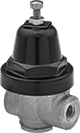
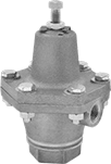
Compact Pressure-Relief Valves
Due to their small size, these valves are often installed on tanks in low-clearance areas. They begin opening at the set pressure. Nylon valves fully open at about 10% over the set pressure and steel valves fully open at about 50% over the set pressure. Valves begin closing as pressure drops and fully close when the system pressure is restored below the set pressure. All have a vent outlet to exhaust discharge directly. Set pressure is not adjustable.
![]() For technical drawings and 3-D models, click on a part number.
For technical drawings and 3-D models, click on a part number.
- For Use With: Grease, Oil
- Temperature Range: Not Rated
Inlet | Each | ||||||||
|---|---|---|---|---|---|---|---|---|---|
| Pipe Size | Location | Maximum Pressure, psi | Relief Port Location | Overall Ht. | Specifications Met | Set Pressure, psi | 1-9 | 10-Up | |
NPTF Male Inlet and Relief Vent | |||||||||
| 1/8 | Bottom | 5 | Top | 1/2" | MS35670 | 1 | 000000 | 00000 | 00000 |
| 1/8 | Bottom | 15 | Top | 1/2" | MS35670 | 7.5 | 000000 | 0000 | 0000 |
| 1/8 | Bottom | 25 | Top | 1/2" | MS35670 | 15 | 000000 | 0000 | 0000 |
| 1/8 | Bottom | 80 | Top | 1/2" | MS35670 | 45 | 000000 | 0000 | 0000 |
| 1/8 | Bottom | 140 | Top | 9/16" | MS35670 | 80 | 0000000 | 0000 | 0000 |
| 1/8 | Bottom | 200 | Top | 1/2" | __ | 100 | 0000000 | 0000 | 0000 |
| 1/8 | Bottom | 650 | Top | 1/2" | __ | 400 | 0000000 | 0000 | 0000 |
BSPT Male Inlet and Relief Vent | |||||||||
| 1/8 | Bottom | 1 | Top | 1/2" | __ | 0.3 | 0000000 | 0000 | 0000 |
| 1/8 | Bottom | 5 | Top | 1/2" | __ | 1 | 0000000 | 0000 | 0000 |
| 1/8 | Bottom | 80 | Top | 1/2" | __ | 45 | 0000000 | 0000 | 0000 |
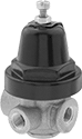
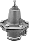
Pressure-Relief Valves for Oil
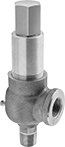
- For Use With: Oil
- Temperature Range: -320° to 420° F
These valves are often used in hydraulic and lubrication systems. They begin opening at the set pressure and fully open at about 10% over the set pressure. Valves begin closing as pressure drops and fully close when the system pressure is restored below the set pressure. Adjust the set pressure within the range.
![]() For technical drawings and 3-D models, click on a part number.
For technical drawings and 3-D models, click on a part number.
Inlet | Relief Port | ||||||||
|---|---|---|---|---|---|---|---|---|---|
| Pipe Size | Location | Maximum Pressure, psi | Pipe Size | Location | Set Pressure Adjustment Method | Overall Ht. | Choose a Set Pressure Range, psi | Each | |
NPT Male Inlet and NPT Female Relief Port | |||||||||
Bronze Body—316 Stainless Steel Seal | |||||||||
| 1/2 | Bottom | 1,400 | 3/4 | Side | External Adjustment Screw | 7 1/4" | 0000000 | 0000000 | |
| 3/4 | Bottom | 1,400 | 3/4 | Side | External Adjustment Screw | 7 1/4" | 0000000 | 000000 | |
| 1 | Bottom | 1,400 | 1 | Side | External Adjustment Screw | 7 1/2" | 0000000 | 000000 | |
| 1 1/4 | Bottom | 1,400 | 1 1/4 | Side | External Adjustment Screw | 8" | 0000000 | 000000 | |
| 1 1/2 | Bottom | 1,400 | 1 1/2 | Side | External Adjustment Screw | 8 7/8" | 0000000 | 00000000 | |
Vibration-Damping Pressure-Regulating
Valves for Water, Oil, Air, and Inert Gas
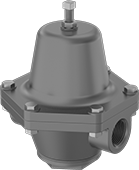
- For Use With: Water, Oil, Air, Inert Gas
- Temperature Range: See Table
A cast iron body absorbs vibration from pressure changes to reduce wear and noise in your pipeline. These valves automatically reduce a high, variable inlet pressure to a lower, stable outlet pressure. Adjust the outlet pressure within the range.
Internal strainers trap debris.
![]() For technical drawings and 3-D models, click on a part number.
For technical drawings and 3-D models, click on a part number.
Inlet | Outlet | ||||||||
|---|---|---|---|---|---|---|---|---|---|
| Pipe Size | Location | Max. Pressure, psi | Pipe Size | Location | Temperature Range | End-to-End Lg. | Choose an Outlet Pressure Range, psi | Each | |
NPT Female | |||||||||
Cast Iron Body—Buna-N Diaphragm and Seal with Internal Strainer | |||||||||
| 1/4 | Side | 200 | 1/4 | Side | 32° to 180° F | 3" | 0000000 | 0000000 | |
| 3/8 | Side | 200 | 3/8 | Side | 32° to 180° F | 3 7/8" | 0000000 | 000000 | |
| 1/2 | Side | 200 | 1/2 | Side | 32° to 180° F | 4 1/2" | 0000000 | 000000 | |
| 3/4 | Side | 200 | 3/4 | Side | 32° to 180° F | 5 1/8" | 0000000 | 000000 | |
| 1 | Side | 200 | 1 | Side | 32° to 180° F | 5 7/8" | 0000000 | 000000 | |
| 1 1/4 | Side | 200 | 1 1/4 | Side | 32° to 180° F | 6 3/4" | 0000000 | 000000 | |
| 1 1/2 | Side | 200 | 1 1/2 | Side | 32° to 180° F | 6 3/4" | 0000000 | 000000 | |
| 2 | Side | 200 | 2 | Side | 32° to 180° F | 9 1/4" | 0000000 | 00000000 | |
Cast Iron Body—Fluoroelastomer Diaphragm and 420 Stainless Steel Seal | |||||||||
| 3/8 | Side | 250 | 3/8 | Side | 32° to 300° F | 4 1/4" | 0000000 | 000000 | |
| 1/2 | Side | 250 | 1/2 | Side | 32° to 300° F | 3 5/8" | 0000000 | 000000 | |
| 3/4 | Side | 250 | 3/4 | Side | 32° to 300° F | 3 5/8" | 0000000 | 000000 | |
| 1 | Side | 250 | 1 | Side | 32° to 300° F | 4 1/2" | 0000000 | 000000 | |
| 2 | Side | 250 | 2 | Side | 32° to 300° F | 6 1/2" | 0000000 | 000000 | |
Pressure-Regulating Valves for Water, Oil, Air, and Inert Gas
Diaphragm And
Gauge Port
Diaphragm
And Gauge Port
- For Use With: Water, Oil, Air, Inert Gas
- Temperature Range: 32° to 180° F
These valves automatically reduce a high, variable inlet pressure to a lower, stable outlet pressure. Adjust the outlet pressure within the range.
Valves with a neoprene diaphragm have higher flow rates than valves with a Buna-N diaphragm.
Internal strainers trap debris.
Gauge ports let you attach a pressure gauge to monitor outlet pressure.
![]() For technical drawings and 3-D models, click on a part number.
For technical drawings and 3-D models, click on a part number.
Inlet | Outlet | |||||||
|---|---|---|---|---|---|---|---|---|
| Pipe Size | Location | Max. Pressure, psi | Pipe Size | Location | End-to-End Lg. | Choose an Outlet Pressure Range, psi | Each | |
Valve | ||||||||
NPT Female | ||||||||
Brass Body—Buna-N Diaphragm and Seal with Internal Strainer | ||||||||
| 1/4 | Side | 250 | 1/4 | Side | 2 1/4" | 0000000 | 0000000 | |
| 3/8 | Side | 250 | 3/8 | Side | 2 1/4" | 0000000 | 000000 | |
Brass Body—Neoprene Diaphragm and Buna-N Seal | ||||||||
| 1/4 | Side | 400 | 1/4 | Side | 2 1/2" | 0000000 | 000000 | |
| 3/8 | Side | 400 | 3/8 | Side | 2 1/2" | 0000000 | 000000 | |
| 1/2 | Side | 400 | 1/2 | Side | 2 7/8" | 0000000 | 000000 | |
Valve with 1/4 NPT Gauge Port | ||||||||
NPT Female | ||||||||
Brass Body—Buna-N Diaphragm and Seal with Internal Strainer | ||||||||
| 1/4 | Side | 250 | 1/4 | Side | 2 1/4" | 0000000 | 000000 | |
| 3/8 | Side | 250 | 3/8 | Side | 2 1/4" | 0000000 | 000000 | |
Brass Body—Neoprene Diaphragm and Buna-N Seal | ||||||||
| 1/4 | Side | 400 | 1/4 | Side | 2 1/2" | 0000000 | 000000 | |
| 3/8 | Side | 400 | 3/8 | Side | 2 1/2" | 0000000 | 000000 | |
| 1/2 | Side | 400 | 1/2 | Side | 2 7/8" | 0000000 | 000000 | |
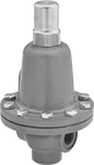
Extended-Life Pressure-Regulating Valves for Water, Oil, Air, and Inert Gas
- For Use With: Water, Oil, Air, Inert Gas
- Temperature Range: 32° to 180° F
For a longer service life than brass and cast iron valves, these have a durable bronze body. They automatically reduce a high, variable inlet pressure to a lower, stable outlet pressure. Adjust the outlet pressure within the range. All valves have an internal strainer to trap debris.
![]() For technical drawings and 3-D models, click on a part number.
For technical drawings and 3-D models, click on a part number.
Inlet | Outlet | |||||||
|---|---|---|---|---|---|---|---|---|
| Pipe Size | Location | Max. Pressure, psi | Pipe Size | Location | End-to-End Lg. | Choose an Outlet Pressure Range, psi | Each | |
NPT Female | ||||||||
Bronze Body—Buna-N Diaphragm and Seal | ||||||||
| 1/4 | Side | 400 | 1/4 | Side | 3" | 00000000 | 0000000 | |
| 3/8 | Side | 400 | 3/8 | Side | 3 7/8" | 00000000 | 000000 | |
| 1/2 | Side | 400 | 1/2 | Side | 4 1/2" | 00000000 | 000000 | |
| 3/4 | Side | 400 | 3/4 | Side | 5 1/8" | 00000000 | 000000 | |
| 1 | Side | 400 | 1 | Side | 5 7/8" | 00000000 | 000000 | |
| 1 1/4 | Side | 400 | 1 1/4 | Side | 6 3/4" | 00000000 | 00000000 | |
| 1 1/2 | Side | 400 | 1 1/2 | Side | 6 3/4" | 00000000 | 00000000 | |
| 2 | Side | 400 | 2 | Side | 9 1/4" | 00000000 | 00000000 | |
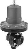
Corrosion-Resistant Pressure-Regulating
Valves for Water, Oil, Air, and Inert Gas
- For Use With: Water, Oil, Air, Inert Gas
- Temperature Range: 32° to 200° F
Often used in wet conditions and harsh environments, these valves have a 316 stainless steel body for excellent corrosion resistance. They automatically reduce a high, variable inlet pressure to a lower, stable outlet pressure. Adjust the outlet pressure within the range.
![]() For technical drawings and 3-D models, click on a part number.
For technical drawings and 3-D models, click on a part number.
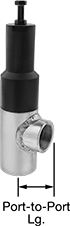
High-Pressure-Regulating Valves for Water, Oil, Air, and Inert Gas
- For Use With: Water, Oil, Air, Inert Gas
- Temperature Range: 32° to 300° F
Withstand more than six times the inlet pressure of standard pressure-regulating valves. These valves automatically reduce a high, variable inlet pressure to a lower, stable outlet pressure. Adjust the outlet pressure within the range. Valves have a 303 stainless steel body for corrosion resistance in harsh environments.
![]() For technical drawings and 3-D models, click on a part number.
For technical drawings and 3-D models, click on a part number.
Inlet | Outlet | |||||||
|---|---|---|---|---|---|---|---|---|
| Pipe Size | Location | Max. Pressure, psi | Pipe Size | Location | Port-to-Port Lg. | Choose an Outlet Pressure Range, psi | Each | |
NPT Female | ||||||||
303 Stainless Steel Body—PTFE Seal | ||||||||
| 2 | Side | 3,000 | 2 | Bottom | 3" | 0000000 | 000000000 | |
High-Temperature Pressure-Regulating Valves for Water, Oil, Air, and Inert Gas
- For Use With: Water, Oil, Air, Inert Gas
- Temperature Range: 32° to 550° F
Rated for more than double the temperature of standard pressure-regulating valves, these can withstand temperatures up to 550° F. They automatically reduce a high, variable inlet pressure to a lower, stable outlet pressure. Adjust the outlet pressure within the range. Valves meet ANSI/FCI 70-2 Class IV for tight shut-off (max. leakage rate of 0.01%).
![]() For technical drawings and 3-D models, click on a part number.
For technical drawings and 3-D models, click on a part number.
Inlet | Outlet | |||||||
|---|---|---|---|---|---|---|---|---|
| Pipe Size | Location | Max. Pressure, psi | Pipe Size | Location | End-to-End Lg. | Choose an Outlet Pressure Range, psi | Each | |
NPT Female | ||||||||
Steel Body—316 Stainless Steel Diaphragm and 303 Stainless Steel Seal | ||||||||
| 1/2 | Side | 300 | 1/2 | Side | 3 5/8" | 00000000 | 000000000 | |
| 3/4 | Side | 300 | 3/4 | Side | 3 5/8" | 00000000 | 00000000 | |
| 1 | Side | 300 | 1 | Side | 4 3/16" | 00000000 | 00000000 | |
| 1 1/2 | Side | 300 | 1 1/2 | Side | 4 13/16" | 00000000 | 00000000 | |
| 2 | Side | 300 | 2 | Side | 5 1/2" | 00000000 | 00000000 | |
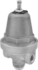
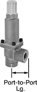
Extended-Life Back-Pressure-Regulating Valves for Water and Oil
- For Use With: Water, Oil
- Temperature Range: -40° to 450° F
For a longer service than cast iron valves, these have a durable bronze body and a 303 stainless steel seal. Commonly installed as bypass lines after centrifugal, reciprocating, and rotary pumps, they obstruct flow to maintain sufficient operating pressure in your system. If the system pressure exceeds the set pressure, they exhaust through the outlet. Adjust the set pressure within the range.
![]() For technical drawings and 3-D models, click on a part number.
For technical drawings and 3-D models, click on a part number.
Inlet | Outlet | |||||||
|---|---|---|---|---|---|---|---|---|
| Pipe Size | Location | Max. Pressure, psi | Pipe Size | Location | Port-to-Port Lg. | Choose an Outlet Pressure Range, psi | Each | |
NPT Female | ||||||||
Bronze Body—303 Stainless Steel Seal | ||||||||
| 1/4 | Bottom | 600 | 1/4 | Side | 1 1/4" | 0000000 | 0000000 | |
| 3/8 | Bottom | 600 | 3/8 | Side | 1 1/4" | 0000000 | 000000 | |
| 1/2 | Bottom | 600 | 1/2 | Side | 1 5/8" | 0000000 | 000000 | |
| 3/4 | Bottom | 600 | 3/4 | Side | 1 5/8" | 0000000 | 000000 | |
| 1 | Bottom | 600 | 1 | Side | 2 1/4" | 0000000 | 000000 | |
| 1 1/4 | Bottom | 600 | 1 1/4 | Side | 2 1/4" | 0000000 | 000000 | |
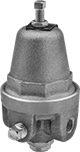
Back-Pressure-Regulating Valves for Water and Oil
- For Use With: Water, Oil
- Temperature Range: -40° to 200° F
Commonly used as bypass lines after centrifugal, reciprocating, and rotary pumps, these valves obstruct flow to maintain sufficient operating pressure in your system. If the system pressure exceeds the set pressure, they exhaust through the threaded relief port. Adjust the set pressure within the range. Valves have a cast iron body that absorbs vibration from pressure changes to reduce wear and noise in your pipeline.
![]() For technical drawings and 3-D models, click on a part number.
For technical drawings and 3-D models, click on a part number.
Inlet | Outlet | Relief Port | ||||||||
|---|---|---|---|---|---|---|---|---|---|---|
| Pipe Size | Location | Max. Pressure, psi | Pipe Size | Location | Pipe Size | Location | End-to-End Lg. | Choose an Outlet Pressure Range, psi | Each | |
NPT Female | ||||||||||
Cast Iron Body—Nickel Alloy Diaphragm and 303 Stainless Steel Seal | ||||||||||
| 1/2 | Side | 400 | 1/2 | Side | 1/2 | Bottom | 2 7/8" | 0000000 | 000000000 | |
| 1 1/4 | Side | 400 | 1 1/4 | Side | 1 1/4 | Bottom | 4 1/4" | 0000000 | 00000000 | |
| 1 1/2 | Side | 400 | 1 1/2 | Side | 1 1/2 | Bottom | 5" | 0000000 | 00000000 | |
| 2 | Side | 400 | 2 | Side | 2 | Bottom | 5" | 0000000 | 00000000 | |
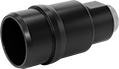
Aluminum Quick-Connect Pipe Fittings for Compressed Air
Twist these fittings onto aluminum pipe for quick, sealed connections—no threading, soldering, or welding necessary. Use them to build a compressed air system in half the time it would take to build a copper or steel system. Also known as Unipipe fittings, they’re part of a quick-connect system that’s compatible with pipe from Unipipe, Transair, and Infinity.
Finger tighten the collar on the end of these fittings, then use a wrench for the final quarter turn. The inside of these fittings has a compression ring and O-ring to seal against the pipe. They’re easy to take apart as needed to modify your setup.
![]() For technical drawings and 3-D models, click on a part number.
For technical drawings and 3-D models, click on a part number.
- For Use With: Air, Coolant, Nitrogen, Oil
- Temperature Range: 0° to 210° F
- Specifications Met: ASME B31.1, ASME B31.3, ASME B31.9
- Pipe Nipples and Pipe: Use Quick-Disconnect Aluminum
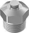
Plugs block the end of a fitting. They include a ¼ BSPP valve that can be used to exhaust your line or attach a pressure gauge. To install, remove the fitting's nut, collar, and grip ring. Insert the plug into the fitting, slide the collar on, and tighten the nut. Discard the connector's grip ring.