


Filter by
System of Measurement
For Use With
Set Pressure
Outlet Pressure
Airflow Capacity
Maximum Inlet Pressure
Set Pressure Configuration
Steam Flow Capacity
Inlet Thread Type
Maximum Temperature
Burst Pressure
Inlet Connection
Export Control Classification Number (ECCN)
DFARS Specialty Metals
About Pressure-Relief Valves
Choose the correct valve type and pipe size to safely manage the pressure of your system.
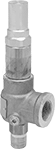
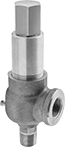
Remote-Discharge ASME-Code Fast-Acting Pressure-Relief Valves for Air and Inert Gas
1 1/4 NPT Male Bottom Inlet × 1 1/2 NPT Female Side Pipe Relief Port
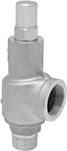 | 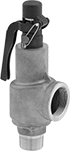 |
Valve | Valve With Test Lever |
Material | |||||||||||
|---|---|---|---|---|---|---|---|---|---|---|---|
Seal | Body | Temp. Range, ° F | Test Mechanism | Overall Ht. | Valve Type | For Use With | Certification | Choose a Set Pressure, psi | Each | ||
| Brass | Bronze | -60 to 406 | Lever | 9 5/8" | Pop Safety | Air, Inert Gas | ASME BPVC.VIII | 15, 20, 25, 30, 35, 40, 45, 50, 55, 60, 65, 70, 75, 80, 85, 90, 95, 100, 105, 110, 115, 120, 125, 130, 135, 140, 145, 150, 175, 200, 225, 250, 275, 300 | 4700K11 | 0000000 | |
| Brass | Bronze | -15 to 406 | — | 8 5/16" | Pop Safety | Air, Inert Gas | ASME BPVC.VIII | 15, 20, 25, 30, 35, 40, 45, 50, 55, 60, 65, 70, 75, 80, 85, 90, 95, 100, 105, 110, 115, 120, 125, 130, 135, 140, 145, 150, 175, 200, 225, 250 | 4673K74 | 000000 | |
| Brass | Bronze | -15 to 406 | Lever | 8 3/4" | Pop Safety | Air, Inert Gas | ASME BPVC.VIII | 15, 20, 25, 30, 35, 40, 45, 50, 55, 60, 65, 70, 75, 80, 85, 90, 95, 100, 105, 110, 115, 120, 125, 130, 135, 140, 145, 150, 175, 200, 225, 250 | 4673K34 | 000000 | |
| Fluoroelastomer | Bronze | -15 to 406 | Lever | 9 5/8" | Pop Safety | Air, Inert Gas | ASME BPVC.VIII | 15, 20, 25, 30, 35, 40, 45, 50, 55, 60, 65, 70, 75, 80, 85, 90, 95, 100, 105, 110, 115, 120, 125, 130, 135, 140, 145, 150, 175, 200, 225, 250, 275, 300 | 6017T14 | 000000 | |
1 1/2 NPT Male Bottom Inlet × 2 NPT Female Side Pipe Relief Port
| |
Valve | Valve With Test Lever |
Material | |||||||||||
|---|---|---|---|---|---|---|---|---|---|---|---|
Seal | Body | Temp. Range, ° F | Test Mechanism | Overall Ht. | Valve Type | For Use With | Certification | Choose a Set Pressure, psi | Each | ||
| Brass | Bronze | -60 to 406 | Lever | 10 5/8" | Pop Safety | Air, Inert Gas | ASME BPVC.VIII | 15, 20, 25, 30, 35, 40, 45, 50, 55, 60, 65, 70, 75, 80, 85, 90, 95, 100, 105, 110, 115, 120, 125, 130, 135, 140, 145, 150, 175, 200, 225, 250, 275, 300 | 4700K15 | 0000000 | |
| Brass | Bronze | -15 to 406 | — | 9 7/16" | Pop Safety | Air, Inert Gas | ASME BPVC.VIII | 15, 20, 25, 30, 35, 40, 45, 50, 55, 60, 65, 70, 75, 80, 85, 90, 95, 100, 105, 110, 115, 120, 125, 130, 135, 140, 145, 150, 175, 200, 225, 250 | 4673K75 | 000000 | |
| Brass | Bronze | -15 to 406 | Lever | 9 3/4" | Pop Safety | Air, Inert Gas | ASME BPVC.VIII | 15, 20, 25, 30, 35, 40, 45, 50, 55, 60, 65, 70, 75, 80, 85, 90, 95, 100, 105, 110, 115, 120, 125, 130, 135, 140, 145, 150, 175, 200, 225, 250 | 4673K35 | 000000 | |
| Fluoroelastomer | Bronze | -15 to 406 | Lever | 10 5/8" | Pop Safety | Air, Inert Gas | ASME BPVC.VIII | 15, 20, 25, 30, 35, 40, 45, 50, 55, 60, 65, 70, 75, 80, 85, 90, 95, 100, 105, 110, 115, 120, 125, 130, 135, 140, 145, 150, 175, 200, 225, 250, 275, 300 | 6017T15 | 000000 | |
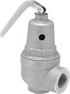
ASME-Code Fast-Acting Pressure-Relief Valves for Steam
NPT Male Inlet and NPT Female Relief Port
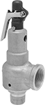 | 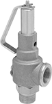 |
Valve With Test Lever | Valve With Swivel Test Lever |
Swivel—Swivel test levers rotate 360° around the valve for use in areas with limited clearance.
Inlet | Relief | ||||||||||||||||
|---|---|---|---|---|---|---|---|---|---|---|---|---|---|---|---|---|---|
Pipe Size | Location | Max. Pressure, psi | Port Pipe Size | Port Location | Shape | Overall Ht. | For Use With | Temp. Range, ° F | Test Mechanism | Test Lever Type | Valve Type | Certification | Choose a Set Pressure, psi | Each | |||
Bronze Body—Brass Seal | |||||||||||||||||
| 1 1/4 | Bottom | 250 | 1 1/2 | Side | 90° Elbow | 9 5/8" | Steam | -60 to 400 | Lever | — | Pop Safety | ASME BPVC.I | 15, 20, 25, 30, 35, 40, 45, 50, 55, 60, 65, 70, 75, 80, 85, 90, 95, 100, 125, 150, 175, 200, 225, 250 | 4700K26 | 0000000 | ||
| 1 1/2 | Bottom | 250 | 1 1/2 | Side | 90° Elbow | 9 5/8" | Steam | -60 to 400 | Lever | Swivel | Pop Safety | ASME BPVC.I | 15, 20, 25, 30, 35, 40, 45, 50, 55, 60, 65, 70, 75, 80, 85, 90, 95, 100, 125, 150, 175, 200, 225, 250 | 4755K15 | 000000 | ||
| 1 1/2 | Bottom | 250 | 2 | Side | 90° Elbow | 10 5/8" | Steam | -60 to 400 | Lever | — | Pop Safety | ASME BPVC.I | 15, 20, 25, 30, 35, 40, 45, 50, 55, 60, 65, 70, 75, 80, 85, 90, 95, 100, 125, 150, 175, 200, 225, 250 | 4700K27 | 000000 | ||
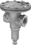
ASME-Code Fast-Acting Pressure-Relief Valves for Water
 |
These valves meet ASME Code Section VIII for use with water pressure vessels. They spring fully open at the set pressure and remain open until the system pressure is restored below the set pressure. All have a threaded relief port that can be attached to a drain line for remote discharge. Body is bronze for durability and a long service life.
Inlet | Relief | ||||||||||||
|---|---|---|---|---|---|---|---|---|---|---|---|---|---|
Pipe Size | Location | Port Pipe Size | Port Location | Overall Ht. | Valve Type | Certification | For Use With | Temp. Range, ° F | Choose a Set Pressure, psi | Each | |||
NPT Male Inlet and NPT Female Relief Port | |||||||||||||
Bronze Body—316 Stainless Steel Seal | |||||||||||||
| 1 1/2 | Bottom | 2 | Side | 13 1/4" | Pop Safety | ASME BPVC.VIII | Water | -60 to 406 | 20, 30, 40, 50, 60, 70, 80, 90, 100, 125, 150, 175, 200, 225, 250, 275, 300 | 6270T16 | 0000000 | ||
ASME-Code Fast-Acting Pressure-Relief Valves for Hot Water
 |
Protect your water-heating system with these valves that meet ASME Code Section IV for hot water heaters and boilers. They spring fully open at the set pressure and remain open until the system pressure is restored below the set pressure. All have a threaded relief port that can be attached to a drain line for remote discharge. Valves have a durable bronze body for a long service life.
Inlet | Relief | |||||||||||||
|---|---|---|---|---|---|---|---|---|---|---|---|---|---|---|
Pipe Size | Location | Port Pipe Size | Port Location | Overall Ht. | Test Mechanism | Valve Type | For Use With | Certification | Temp. Range, ° F | Choose a Set Pressure, psi | Each | |||
NPT Female Inlet and Relief Port | ||||||||||||||
Bronze Body—Silicone Seal | ||||||||||||||
| 1 1/4 | Bottom | 1 1/2 | Side | 8 3/8" | Lever | Pop Safety | Water | ASME BPVC.IV | 33 to 250 | 30, 50, 60, 75, 100, 125, 150 | 4702K53 | 0000000 | ||
| 1 1/2 | Bottom | 2 | Side | 10 13/16" | Lever | Pop Safety | Water | ASME BPVC.IV | 33 to 250 | 30, 50, 60, 75, 100, 125, 150 | 4702K54 | 000000 | ||
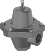
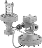
Back-Pressure-Regulating Valves for Water and Oil
 |
Commonly used as bypass lines after centrifugal, reciprocating, and rotary pumps, these valves obstruct flow to maintain sufficient operating pressure in your system. If the system pressure exceeds the set pressure, they exhaust through the threaded relief port. Adjust the set pressure within the range. Valves have a cast iron body that absorbs vibration from pressure changes to reduce wear and noise in your pipeline.
Inlet | Outlet | Relief Port | |||||||||||||
|---|---|---|---|---|---|---|---|---|---|---|---|---|---|---|---|
Pipe Size | Location | Max. Pressure, psi | Pipe Size | Location | Pressure Adjustment Method | Pipe Size | Location | End-to-End Lg. | For Use With | Temp. Range, ° F | Choose an Outlet Pressure, psi | Each | |||
NPT Female | |||||||||||||||
Cast Iron Body—Nickel Diaphragm and 303 Stainless Steel Seal | |||||||||||||||
| 1 1/2 | Side | 400 | 1 1/2 | Side | Screw | 1 1/2 | Bottom | 5" | Water, Oil | -40 to 200 | 10 to 55, 30 to 100, 40 to 200, 125 to 300, 200 to 400 | 4675K26 | 000000000 | ||
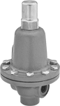
Precision-Adjustment Pressure-Relief Valves for Fuel
NPT Male Inlet and NPT Female Relief Port
 |
Bronze Body—Valves with a bronze body are harder and more durable than valves with a brass body for a longer service life.
Inlet | Relief | ||||||||||||||
|---|---|---|---|---|---|---|---|---|---|---|---|---|---|---|---|
Pipe Size | Location | Max. Pressure, psi | Port Pipe Size | Port Location | Set Pressure Adjustment Method | Shape | Overall Ht. | For Use With | Temp. Range, ° F | Valve Type | Choose a Set Pressure, psi | Each | |||
Bronze Body—Bronze Seal | |||||||||||||||
| 1 1/2 | Bottom | 400 | 1 1/2 | Side | External Adjustment Screw | 90° Elbow | 9 1/2" | Diesel Fuel, Fuel Oil, Gasoline, Kerosene | -60 to 450 | Relief | 0 to 14, 15 to 25, 26 to 40, 41 to 75, 76 to 110, 111 to 130, 131 to 150, 151 to 200, 201 to 400 | 4703K58 | 0000000 | ||
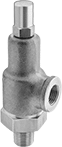
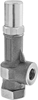
Pressure-Relief Valves for Oil
NPT Male Inlet and NPT Female Relief Port
 |
Inlet | Relief | ||||||||||||||
|---|---|---|---|---|---|---|---|---|---|---|---|---|---|---|---|
Pipe Size | Location | Max. Pressure, psi | Port Pipe Size | Port Location | Set Pressure Adjustment Method | Shape | Overall Ht. | For Use With | Temp. Range, ° F | Valve Type | Choose a Set Pressure, psi | Each | |||
Bronze Body—316 Stainless Steel Seal | |||||||||||||||
| 1 1/2 | Bottom | 1,400 | 1 1/2 | Side | External Adjustment Screw | 90° Elbow | 8 7/8" | Oil | -320 to 420 | Relief | 15 to 75, 50 to 150, 100 to 300, 200 to 600 | 4460K85 | 000000000 | ||
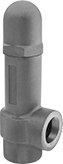
ASME-Code Fast-Acting Pressure-Relief Valves for Low-Pressure Steam
90° Elbow
 |
Threaded—Threaded relief ports can be attached to a drain line for remote discharge.
Inlet | Relief | |||||||||||||||||||||
|---|---|---|---|---|---|---|---|---|---|---|---|---|---|---|---|---|---|---|---|---|---|---|
Pipe Size | Thread Type | Gender | Location | Max. Pressure, psi | Port Pipe Size | Port | Port Fitting Connection | Port Thread Type | Port Gender | Port Location | Steam Flow Cap., lb/hr | Set Pressure, psi | Overall Ht. | Test Mechanism | Valve Type | For Use With | Certification | Max. Temp., ° F | Each | |||
Bronze Body—PTFE-Coated EPDM Seal | ||||||||||||||||||||||
| 1 1/4 | NPT | Male | Bottom | 15 | 1 1/2 | Pipe | Threaded | NPT | Female | Side | 1,200 | 15 | 4 1/2" | Lever | Pop Safety | Steam | ASME BPVC.IV | 250 | 4699K55 | 0000000 | ||
| 1 1/2 | NPT | Male | Bottom | 15 | 2 | Pipe | Threaded | NPT | Female | Side | 1,900 | 15 | 5 1/4" | Lever | Pop Safety | Steam | ASME BPVC.IV | 250 | 4699K65 | 000000 | ||
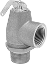
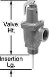
Fast-Acting Temperature- and Pressure-Relief Valves for Hot Water
NPT Male Inlet and NPT Female Relief Port
 |
Male × Female |
ASME BPVC.IV Certified—Valves with 3/4 to 2 pipe size meet ASME Code Section IV for hot water.
Inlet | Relief | Set Pressure | |||||||||||||||||
|---|---|---|---|---|---|---|---|---|---|---|---|---|---|---|---|---|---|---|---|
Pipe Size | Location | Max. Pressure, psi | Port Pipe Size | Port Location | Range, psi | Temp., ° F | Shape | Hot Water Flow Cap., BTU/hr | Insertion Lg. | Valve Ht. | Overall Ht. | For Use With | Test Mechanism | Valve Type | Certification | Each | |||
Bronze Body—Silicone Seal | |||||||||||||||||||
| 2 | Bottom | 150 | 1 1/2 | Side | 150 | 210 | 90° Elbow | 1,200,000 | 3" | 8 1/2" | 11 1/2" | Water | Lever | Pop Safety | ASME BPVC.IV, CSA Certified | 9761K17 | 000000000 | ||
Adjustable Pressure-Relief Valves for Fuel
NPT Female Inlet and Relief Port
 |
Inlet | Relief | ||||||||||||||
|---|---|---|---|---|---|---|---|---|---|---|---|---|---|---|---|
Pipe Size | Location | Max. Pressure, psi | Port Pipe Size | Port Location | Set Pressure Adjustment Method | Shape | Overall Ht. | For Use With | Temp. Range, ° F | Valve Type | Choose a Set Pressure, psi | Each | |||
Brass Body—416 Stainless Steel Seal | |||||||||||||||
| 1 1/2 | Bottom | 1,000 | 1 1/2 | Side | External Adjustment Screw | 90° Elbow | 11 1/16" | Diesel Fuel, Fuel Oil, Gasoline, Kerosene | -20 to 400 | Relief | 3 to 10, 7 to 35, 30 to 100, 60 to 175, 150 to 350, 300 to 500 | 7844K56 | 0000000 | ||
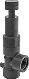
Adjustable Pressure-Relief Valves for Chemicals
NPT Female Inlet and Relief Port
 |
Inlet | Relief | Set Pressure | |||||||||||||||
|---|---|---|---|---|---|---|---|---|---|---|---|---|---|---|---|---|---|
Pipe Size | Location | Max. Pressure, psi | Port Pipe Size | Port Location | Range, psi | Adjustment Method | Shape | Features | Overall Ht. | Gauge Port Pipe Size | For Use With | Temp. Range, ° F | Valve Type | Each | |||
Dark Gray PVC Body—EPDM Seal | |||||||||||||||||
| 1 1/2 | Bottom | 150 | 1 1/2 | Side | 5 to 75 | External Adjustment Screw | 90° Elbow | Gauge Port | 13 1/4" | 1/4 | Aluminum Chloride, Boric Acid | 40 to 140 | Relief | 5007K64 | 000000000 | ||
Flange-Mount Pressure-Relief Discs
Pressure-Relief Discs
 |
Operating Ratio—Operating ratio is the ratio between the normal operating pressure and the burst pressure. Exceeding the operating ratio decreases the service life of the disc. For example, a disc with a burst pressure of 100 psi and an operating ratio of 80% should not be used in a system with an operating pressure greater than 80 psi.
Vacuum Rated Pressure-Relief Discs
 |
Vacuum-rated discs have supports to resist rupture caused by vacuum.
Operating Ratio—Operating ratio is the ratio between the normal operating pressure and the burst pressure. Exceeding the operating ratio decreases the service life of the disc. For example, a disc with a burst pressure of 100 psi and an operating ratio of 80% should not be used in a system with an operating pressure greater than 80 psi.
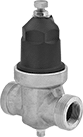
Heavy Duty Pressure-Regulating Valves for Water and Air
 |
Thicker walls and a 304 stainless steel seal make these valves tougher than brass pressure-regulating valves. They automatically reduce a high, variable inlet pressure to a lower, stable outlet pressure. Adjust the outlet pressure within the range. Valves have an internal strainer to trap debris. Body is bronze for durability and a long service life.
Inlet | Outlet | ||||||||||||
|---|---|---|---|---|---|---|---|---|---|---|---|---|---|
Pipe Size | Location | Max. Pressure, psi | Pipe Size | Location | Pressure Adjustment Method | End-to-End Lg. | For Use With | Temp. Range, ° F | Choose an Outlet Pressure, psi | Each | |||
NPT Female | |||||||||||||
Bronze Body—EPM Rubber Diaphragm and 304 Stainless Steel Seal with Internal Strainer | |||||||||||||
| 1 1/2 | Side | 300 | 1 1/2 | Side | Screw | 8 7/8" | Water, Air | 32 to 180 | 20 to 70, 71 to 150 | 4676K55 | 000000000 | ||
Pressure-Regulating Valves for Chemicals
 |
A plastic body and fluoroelastomer seal stand up to harsh chemicals. These valves automatically reduce a high, variable inlet pressure to a lower, stable outlet pressure. Adjust the outlet pressure within the range.
Inlet | Outlet | ||||||||||||
|---|---|---|---|---|---|---|---|---|---|---|---|---|---|
Pipe Size | Location | Max. Pressure, psi | Pipe Size | Location | Pressure Range, psi | Pressure Adjustment Method | End-to-End Lg. | For Use With | Temp. Range, ° F | Each | |||
NPT Female | |||||||||||||
PVC Body—Fluoroelastomer Seal | |||||||||||||
| 1 1/2 | Side | 125 | 1 1/2 | Side | 10 to 80 | Screw | 6 1/8" | Chemicals | 40 to 140 | 45965K34 | 000000000 | ||
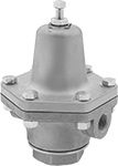
High-Temperature Pressure-Regulating Valves for Water, Oil, Air, and Inert Gas
 |
Rated for more than double the temperature of standard pressure-regulating valves, these can withstand temperatures up to 550° F. They automatically reduce a high, variable inlet pressure to a lower, stable outlet pressure. Adjust the outlet pressure within the range. Valves meet ANSI/FCI 70-2 Class IV for tight shut-off (max. leakage rate of 0.01%).
Inlet | Outlet | |||||||||||||
|---|---|---|---|---|---|---|---|---|---|---|---|---|---|---|
Pipe Size | Location | Max. Pressure, psi | Pipe Size | Location | Pressure Adjustment Method | End-to-End Lg. | For Use With | Temp. Range, ° F | Specs. Met | Choose an Outlet Pressure, psi | Each | |||
NPT Female | ||||||||||||||
Steel Body—316 Stainless Steel Diaphragm and 303 Stainless Steel Seal | ||||||||||||||
| 1 1/2 | Side | 300 | 1 1/2 | Side | Screw | 4 13/16" | Water, Oil, Air, Inert Gas | 32 to 550 | ANSI/FCI 70-2 Class IV | 5 to 20, 10 to 30, 20 to 45, 30 to 95, 60 to 160 | 46395K27 | 000000000 | ||
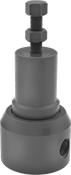
Hydraulic Pressure-Relief Valves
 |
Iron |
To set the pressure, unscrew the cap and turn the adjustment screw. Valves begin opening at the set pressure and fully open at about 10% over the set pressure. They begin closing as pressure drops and close when the system pressure is restored below the set pressure.
Iron Body—Iron valves absorb vibration to reduce noise and wear in the pipeline.
Inlet Connection | Relief Connection | Overall | ||||||||||
|---|---|---|---|---|---|---|---|---|---|---|---|---|
Pipe Size | Dash Size | Pipe Size | Dash Size | Lg. | Wd. | Ht. | Temp. Range, ° F | Choose a Set Pressure, psi | Each | |||
NPT Female Inlet and NPT Female Relief Port | ||||||||||||
Iron Body | ||||||||||||
| 1 1/2 | 24 | 1 1/2 | 24 | 4 1/8" | 2 7/8" | 11 1/16" | -20 to 400 | 3 to 10, 7 to 35, 30 to 100, 60 to 175, 150 to 350, 300 to 500 | 4704K25 | 0000000 | ||
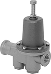
Vibration-Damping Pressure-Regulating Valves for Water, Oil, Air, and Inert Gas
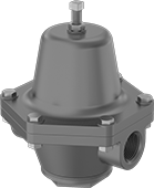 |
A cast iron body absorbs vibration from pressure changes to reduce wear and noise in your pipeline. These valves automatically reduce a high, variable inlet pressure to a lower, stable outlet pressure. Adjust the outlet pressure within the range.
Internal Strainer—Internal strainers trap debris.
Inlet | Outlet | ||||||||||||
|---|---|---|---|---|---|---|---|---|---|---|---|---|---|
Pipe Size | Location | Max. Pressure, psi | Pipe Size | Location | Pressure Adjustment Method | End-to-End Lg. | For Use With | Temp. Range, ° F | Choose an Outlet Pressure, psi | Each | |||
NPT Female | |||||||||||||
Cast Iron Body—Buna-N Diaphragm and Seal with Internal Strainer | |||||||||||||
| 1 1/2 | Side | 200 | 1 1/2 | Side | Screw | 6 3/4" | Water, Oil, Air, Inert Gas | 32 to 180 | 2 to 15, 10 to 30, 20 to 50, 45 to 100, 90 to 125 | 4674K47 | 0000000 | ||
Long-Life Pressure-Regulating Valves for Water, Oil, Air, and Inert Gas
 |
For a longer service life than brass and cast iron valves, these have a durable bronze body. They automatically reduce a high, variable inlet pressure to a lower, stable outlet pressure. Adjust the outlet pressure within the range. All valves have an internal strainer to trap debris.
Inlet | Outlet | ||||||||||||
|---|---|---|---|---|---|---|---|---|---|---|---|---|---|
Pipe Size | Location | Max. Pressure, psi | Pipe Size | Location | Pressure Adjustment Method | End-to-End Lg. | For Use With | Temp. Range, ° F | Choose an Outlet Pressure, psi | Each | |||
NPT Female | |||||||||||||
Bronze Body—Buna-N Diaphragm and Seal with Internal Strainer | |||||||||||||
| 1 1/2 | Side | 400 | 1 1/2 | Side | Screw | 6 3/4" | Water, Oil, Air, Inert Gas | 32 to 180 | 2 to 15, 10 to 30, 20 to 50, 45 to 100, 90 to 150 | 47345K17 | 000000000 | ||
Quick-Set Pressure-Regulating Valves for Water
 |
Change outlet pressure without using a gauge—turn the dial to adjust the outlet pressure in 5 or 10 psi increments. These valves automatically reduce a high, variable inlet pressure to a lower, stable outlet pressure. They also have an internal strainer to trap debris. Union fittings on both ends of the valves disassemble for easy valve installation and removal. All of these valves meet Canadian safety standards for pressure-reducing valves. Some also meet American and international plumbing safety and performance standards.
Brass Body—Brass valves are durable and have a long service life. Their gauge ports let you attach a pressure gauge to measure the pressure flowing in and out of the valve.
Inlet | Outlet | Gauge Port | |||||||||||||||
|---|---|---|---|---|---|---|---|---|---|---|---|---|---|---|---|---|---|
Pipe Size | Location | Max. Pressure, psi | Pipe Size | Location | Pressure Range, psi | Pressure Adjustment Method | Pipe Size | Location | Connection | End-to-End Lg. | For Use With | Temp. Range, ° F | Certification | Each | |||
NPT Female | |||||||||||||||||
Brass Body—EPDM Diaphragm and Seal | |||||||||||||||||
| 1 1/2 | Side | 250 | 1 1/2 | Side | 25 to 90 | Dial | 1/4 | Side | NPT Female | 7 7/8" | Water | 33 to 140 | CSA Certified | 45805K71 | 0000000 | ||
Extended-Life Vacuum-Regulating Valves for Air and Inert Gas
 |
For a longer service life than brass vacuum-regulating valves, these are made of bronze for strength and durability. They throttle a high vacuum source to maintain a lower vacuum level in your system. Turning the adjustment screw will adjust the vacuum setting.
Inlet | Outlet | |||||||||||
|---|---|---|---|---|---|---|---|---|---|---|---|---|
Pipe Size | Location | Pipe Size | Location | Vacuum Range, in. Hg | Vacuum Adjustment Method | End-to-End Lg. | For Use With | Temp. Range, ° F | Each | |||
NPT Female | ||||||||||||
Bronze Body—Neoprene Diaphragm and Chrome-Plated Bronze Seal | ||||||||||||
| 1 1/2 | Side | 1 1/2 | Side | 8 to 30 | Screw | 5 3/4" | Air, Inert Gas | -20 to 180 | 4710K18 | 000000000 | ||
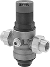
Pressure-Regulating Valves for Drinking Water
 | 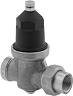 |
Valves | Valves With Union Fitting |
These valves meet NSF/ANSI 61 for use in drinking water systems. They automatically reduce a high, variable inlet pressure to a lower, stable outlet pressure. Adjust the outlet pressure within the range. All valves have a gauge port. An internal strainer traps debris. Body is bronze for durability and a long service life.
Union Fitting—Valves with union fitting disassemble for easy installation and removal.
Inlet | Outlet | Gauge Port | |||||||||||||||||
|---|---|---|---|---|---|---|---|---|---|---|---|---|---|---|---|---|---|---|---|
Pipe Size | Location | Max. Pressure, psi | Pipe Size | Location | Pressure Range, psi | Pressure Adjustment Method | Pressure Gauge Included | Pipe Size | Location | Connection | End-to-End Lg. | For Use With | Temp. Range, ° F | Certification | Food Industry Std. | Each | |||
NPT Female | |||||||||||||||||||
Bronze Body—Buna-N Diaphragm and Seal with Internal Strainer and Union Fitting | |||||||||||||||||||
| 1 1/2 | Side | 300 | 1 1/2 | Side | 25 to 75 | Screw | No | 1/4 | Bottom | NPT Female | 6 5/16" | Drinking Water | 33 to 140 | ASSE 1003 Listed, CSA Certified, IAPMO Listed | NSF/ANSI 61 | 4946K25 | 0000000 | ||
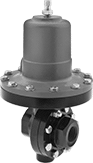
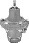
Pressure-Regulating Valves for Steam
 |
Automatically reduce a high, variable inlet pressure in your steam system to a lower, stable outlet pressure. Adjust the outlet pressure within the range. These valves have a cast iron body that absorbs vibration from pressure changes to reduce wear and noise in your pipeline.
Internal Strainer—Internal strainers trap debris.
Valves | Repair Kits | ||||||||||||||
|---|---|---|---|---|---|---|---|---|---|---|---|---|---|---|---|
Inlet | Outlet | ||||||||||||||
Pipe Size | Location | Max. Pressure, psi | Pipe Size | Location | Pressure Adjustment Method | End-to-End Lg. | For Use With | Temp. Range, ° F | Choose an Outlet Pressure, psi | Each | Each | ||||
NPT Female | |||||||||||||||
Cast Iron Body—Bronze Diaphragm and 420 Stainless Steel Seal | |||||||||||||||
| 1 1/2 | Side | 250 | 1 1/2 | Side | Screw | 6 1/2" | Steam | -20 to 400 | 0 to 10, 10 to 30, 30 to 50, 40 to 85 | 9796K93 | 0000000 | 9796K99 | 0000000 | ||
Cast Iron Body—Bronze Diaphragm and PTFE Seal with Internal Strainer | |||||||||||||||
| 1 1/2 | Side | 150 | 1 1/2 | Side | Screw | 6 3/4" | Steam | -20 to 400 | 2 to 15, 10 to 30, 20 to 50, 45 to 100, 90 to 150 | 4674K67 | 000000 | 4674K94 | 000000 | ||
High-Accuracy Pressure-Regulating Valves for Steam
 |
Control steam line pressure with ±1 psi accuracy. These valves automatically reduce a high, variable inlet pressure to a lower, stable outlet pressure. Adjust the outlet pressure within the range. Valves have a cast iron body that absorbs vibration from pressure changes to reduce wear and noise in your pipeline. They meet ANSI/FCI 70-2 Class IV for tight shut-off (max. leakage rate of 0.01%). Install 1/4 NPT male pipe (not included) between the control valve and your downstream steam line.
Repair Kits—Repair kits (sold separately) include replacement seals, diaphragm, spring, and spring assembly.
Valves | Repair Kits | ||||||||||||||
|---|---|---|---|---|---|---|---|---|---|---|---|---|---|---|---|
Inlet | Outlet | ||||||||||||||
Pipe Size | Location | Max. Pressure, psi | Pipe Size | Location | Pressure Adjustment Method | For Use With | Temp. Range, ° F | Specs. Met | Choose an Outlet Pressure, psi | Each | Each | ||||
NPT Female | |||||||||||||||
Cast Iron Body—301 Stainless Steel Diaphragm and 420 Stainless Steel Seal | |||||||||||||||
| 1 1/2 | Side | 250 | 1 1/2 | Side | Screw | Steam | 40 to 450 | ANSI/FCI 70-2 Class IV | 3 to 20, 5 to 50, 10 to 100, 20 to 150 | 9792K27 | 000000000 | 9792K36 | 0000000 | ||
Long-Life Pressure-Regulating Valves for Steam
 |
For a longer service life than cast iron valves, these have a durable bronze body. All automatically reduce a high, variable inlet pressure to a lower, stable outlet pressure. Adjust the outlet pressure within the range. Valves have an internal strainer to trap debris.
Inlet | Outlet | ||||||||||||
|---|---|---|---|---|---|---|---|---|---|---|---|---|---|
Pipe Size | Location | Max. Pressure, psi | Pipe Size | Location | Pressure Adjustment Method | End-to-End Lg. | For Use With | Temp. Range, ° F | Choose an Outlet Pressure, psi | Each | |||
NPT Female | |||||||||||||
Bronze Body—Bronze Diaphragm and PTFE Seal with Internal Strainer | |||||||||||||
| 1 1/2 | Side | 250 | 1 1/2 | Side | Screw | 6 3/4" | Steam | -20 to 400 | 2 to 15, 10 to 30, 20 to 50, 45 to 100, 90 to 150 | 47345K37 | 000000000 | ||
