How to Identify and Measure Fittings
Pipe size is an industry designation, not the actual size. View information about how to measure threaded and unthreaded pipe and pipe fittings.
More
About Gas Regulators
More
Precision Extreme-Pressure Brass Threaded Pipe Fittings
Also known as instrumentation fittings, these have the most precise threads and the tightest tolerances of all the brass pipe fittings we offer. Fittings are brass for good corrosion resistance.

- For Use With: Air, Argon, Natural Gas, Nitrogen Gas, Oil, Oxygen, Steam, Water
- Specifications Met: See table
Pipe Size | ||||||
|---|---|---|---|---|---|---|
| (A) | (B) | Max. Pressure | Max. Steam Pressure | Specifications Met | Each | |
NPT Female × NPT Male | ||||||
| 1/8 | 1/16 | 3,200 psi @ 72° F | 1,500 psi @ 300° F | ASME B1.20.1, ASME B31.3 | 00000000 | 00000 |
| 1/4 | 1/8 | 4,300 psi @ 72° F | 1,500 psi @ 300° F | ASME B1.20.1, ASME B31.1, ASME B31.3 | 0000000 | 00000 |
| 3/8 | 1/8 | 3,500 psi @ 72° F | 1,500 psi @ 300° F | ASME B1.20.1, ASME B31.1, ASME B31.3 | 00000000 | 00000 |
| 3/8 | 1/4 | 3,500 psi @ 72° F | 1,500 psi @ 300° F | ASME B1.20.1, ASME B31.1, ASME B31.3 | 0000000 | 00000 |
| 1/2 | 1/4 | 2,400 psi @ 72° F | 1,500 psi @ 300° F | ASME B1.20.1, ASME B31.3 | 00000000 | 00000 |
| 1/2 | 3/8 | 2,400 psi @ 72° F | 1,500 psi @ 300° F | ASME B1.20.1, ASME B31.3 | 00000000 | 00000 |
| 3/4 | 1/2 | 3,000 psi @ 72° F | 1,500 psi @ 300° F | ASME B1.20.1, ASME B31.1, ASME B31.3 | 00000000 | 00000 |

- For Use With: Air, Argon, Natural Gas, Nitrogen Gas, Oil, Oxygen, Steam, Water
- Specifications Met: See table
Pipe Size | ||||||
|---|---|---|---|---|---|---|
| (A) | (B) | Max. Pressure | Max. Steam Pressure | Specifications Met | Each | |
NPT Male × NPT Female | ||||||
| 1/4 | 1/8 | 3,600 psi @ 72° F | 1,500 psi @ 300° F | ASME B1.20.1, ASME B31.1, ASME B31.3 | 0000000 | 000000 |
| 3/8 | 1/8 | 3,200 psi @ 72° F | 1,500 psi @ 300° F | ASME B1.20.1, ASME B31.3 | 00000000 | 0000 |
| 3/8 | 1/4 | 3,000 psi @ 72° F | 1,500 psi @ 300° F | ASME B1.20.1, ASME B31.1, ASME B31.3 | 0000000 | 00000 |
| 1/2 | 1/8 | 3,200 psi @ 72° F | 1,500 psi @ 300° F | ASME B1.20.1, ASME B31.3 | 00000000 | 00000 |
| 1/2 | 1/4 | 3,900 psi @ 72° F | 1,500 psi @ 300° F | ASME B1.20.1, ASME B31.1, ASME B31.3 | 0000000 | 00000 |
| 1/2 | 3/8 | 2,800 psi @ 72° F | 1,500 psi @ 300° F | ASME B1.20.1, ASME B31.1, ASME B31.3 | 0000000 | 00000 |
| 3/4 | 1/2 | 2,800 psi @ 72° F | 1,500 psi @ 300° F | ASME B1.20.1, ASME B31.1, ASME B31.3 | 0000000 | 00000 |

- For Use With: Air, Argon, Natural Gas, Nitrogen Gas, Oil, Oxygen, Steam, Water
- Specifications Met: See table
Pipe Size | ||||||
|---|---|---|---|---|---|---|
| (A) | (B) | Max. Pressure | Max. Steam Pressure | Specifications Met | Each | |
NPT Female | ||||||
| 1/8 | 1/16 | 4,000 psi @ 72° F | 1,500 psi @ 300° F | ASME B1.20.1, ASME B31.1, ASME B31.3 | 0000000 | 000000 |
| 1/4 | 1/8 | 3,200 psi @ 72° F | 1,500 psi @ 300° F | ASME B1.20.1, ASME B31.3 | 00000000 | 0000 |
| 3/8 | 1/4 | 2,600 psi @ 72° F | 1,500 psi @ 300° F | ASME B1.20.1, ASME B31.3 | 00000000 | 00000 |
| 1/2 | 1/4 | 3,600 psi @ 72° F | 1,500 psi @ 300° F | ASME B1.20.1, ASME B31.1, ASME B31.3 | 0000000 | 00000 |
| 1/2 | 3/8 | 2,400 psi @ 72° F | 1,500 psi @ 300° F | ASME B1.20.1, ASME B31.3 | 00000000 | 00000 |
| 3/4 | 1/2 | 2,300 psi @ 72° F | 1,500 psi @ 300° F | ASME B1.20.1, ASME B31.3 | 00000000 | 00000 |

- For Use With: Air, Argon, Natural Gas, Nitrogen Gas, Oil, Oxygen, Steam, Water
- Specifications Met: See table
Pipe Size | ||||||
|---|---|---|---|---|---|---|
| (A) | (B) | Max. Pressure | Max. Steam Pressure | Specifications Met | Each | |
NPT Male | ||||||
| 1/8 | 1/16 | 5,000 psi @ 72° F | 1,500 psi @ 300° F | ASME B1.20.1, ASME B31.3 | 00000000 | 000000 |
| 1/4 | 1/8 | 4,100 psi @ 72° F | 1,500 psi @ 300° F | ASME B1.20.1, ASME B31.1, ASME B31.3 | 00000000 | 00000 |
| 3/8 | 1/8 | 3,900 psi @ 72° F | 1,500 psi @ 300° F | ASME B1.20.1, ASME B31.3 | 00000000 | 0000 |
| 3/8 | 1/4 | 4,000 psi @ 72° F | 1,500 psi @ 300° F | ASME B1.20.1, ASME B31.1, ASME B31.3 | 00000000 | 00000 |
| 1/2 | 1/4 | 3,900 psi @ 72° F | 1,500 psi @ 300° F | ASME B1.20.1, ASME B31.1, ASME B31.3 | 00000000 | 00000 |
| 1/2 | 3/8 | 3,900 psi @ 72° F | 1,500 psi @ 300° F | ASME B1.20.1, ASME B31.1, ASME B31.3 | 00000000 | 00000 |
| 3/4 | 1/2 | 3,800 psi @ 72° F | 1,500 psi @ 300° F | ASME B1.20.1, ASME B31.1, ASME B31.3 | 00000000 | 00000 |

- For Use With: Air, Argon, Natural Gas, Nitrogen Gas, Oil, Oxygen, Steam, Water
- Specifications Met: ASME B1.20.1, ASME B31.1, ASME B31.3
Ultra-High-Polish Gasket Fittings for Stainless Steel Tubing
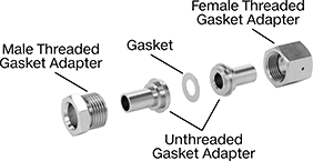
- For Use With: Ammonia, Argon, Butane, Carbon Dioxide, Chloride, Fluoride, Fluorocarbon, Germane, Halide, Helium, Hydrogen, Krypton, Laser Gas, Natural Gas, Neon, Nitrogen, Oxygen, Silane, Sulfur Hexafluoride, Tungsten Hexafluoride, Xenon
- Temperature Range: -420° to 1000° F
- Tubing: Use with 316/316L stainless steel
- Compatible With: Swagelok® VCR
Polished to at least a 15 Ra finish on the inside, these fittings have an ultra-smooth interior surface that helps prevent contamination. Also known as ultra-high-purity fittings, they’re packed in a Class 100 clean room, cleaned, and double bagged. They are commonly used in semiconductor applications. Fittings use a metal gasket (sold separately), which generates fewer particles than a rubber gasket and creates a strong seal in high-pressure and ultra-high-vacuum applications. Fittings are 316 stainless steel for excellent corrosion resistance.
To assemble, place a gasket between the gasket ends before gently rotating the female-threaded fitting onto the male-threaded fitting. Tighten until 1/8 of a turn past finger tight.
Choose threaded fittings to attach directly to other fittings. Or, choose one of the following types of fittings to attach directly to tubing:
Butt-weld fittings allow for a smooth, flush connection that provides maximum flow.
Yor-Lok fittings have two sleeves that bite into tubing as you tighten the nut, creating a strong steal without the need for welding. They're also known as instrumentation fittings.
Tube stem fittings connect to Yor-Lok fittings (sold separately).

| For Tube OD (A) | For Tube OD (B) | Material | Max. Pressure | Max. Vacuum | Interior Smoothness, Ra | Environmental Rating | Each | |
| 1/2" | 1/4" | 316L Stainless Steel | 3,750 psi @ 72° F | 10 -11 torr @ 72° F | 5 | Fed. Std. Class 100 | 00000000 | 000000 |
For Tube (Yor-Lok) | |||||||||
|---|---|---|---|---|---|---|---|---|---|
| For Tube OD (Gasket) | OD | Wall Thick. | Material | Max. Pressure | Max. Vacuum | Interior Smoothness, Ra | Environmental Rating | Each | |
| 1/4" | 1/8" | 0.035" | 316L Stainless Steel | 5,100 psi @ 72° F | 10 -11 torr @ 72° F | 5 | Fed. Std. Class 100 | 00000000 | 000000 |
| 1/4" | 3/8" | 0.035" | 316L Stainless Steel | 5,100 psi @ 72° F | 10 -11 torr @ 72° F | 5 | Fed. Std. Class 100 | 00000000 | 00000 |
Adapters with an unthreaded gasket fitting connection are also known as glands.
For Tube OD | ||||||||||
|---|---|---|---|---|---|---|---|---|---|---|
| Gasket | Butt Weld | Wall Thick. | Lg. | Material | Max. Pressure | Max. Vacuum | Interior Smoothness, Ra | Environmental Rating | Each | |
| 1/4" | 1/8" | 0.028" | 1 3/32" | 316L Stainless Steel | 5,100 psi @ 72° F | 10 -11 torr @ 72° F | 5 | Fed. Std. Class 100 | 00000000 | 000000 |
| 1/4" | 1/8" | 0.028" | 1 13/32" | 316L Stainless Steel | 5,100 psi @ 72° F | 10 -11 torr @ 72° F | 5 | Fed. Std. Class 100 | 00000000 | 00000 |
| 1/2" | 1/4" | 0.035" | 1 1/8" | 316L Stainless Steel | 3,750 psi @ 72° F | 10 -11 torr @ 72° F | 5 | Fed. Std. Class 100 | 00000000 | 00000 |
| 1/2" | 1/4" | 0.035" | 1 25/32" | 316L Stainless Steel | 3,750 psi @ 72° F | 10 -11 torr @ 72° F | 5 | Fed. Std. Class 100 | 00000000 | 00000 |
| 1/2" | 3/8" | 0.035" | 1 1/8" | 316L Stainless Steel | 3,750 psi @ 72° F | 10 -11 torr @ 72° F | 5 | Fed. Std. Class 100 | 00000000 | 00000 |
| 1/2" | 3/8" | 0.035" | 1 25/32" | 316L Stainless Steel | 3,750 psi @ 72° F | 10 -11 torr @ 72° F | 5 | Fed. Std. Class 100 | 00000000 | 00000 |
Adapters with an unthreaded gasket fitting connection are also known as glands.
| For Tube OD (Gasket) | Tube Stem OD | Wall Thick. | Material | Max. Pressure | Max. Vacuum | Interior Smoothness, Ra | Environmental Rating | Each | |
| 1/2" | 3/8" | 0.049" | 316L Stainless Steel | 3,750 psi @ 72° F | 10 -11 torr @ 72° F | 5 | Fed. Std. Class 100 | 00000000 | 000000 |


| For Tube OD | Nut Material | Max. Pressure | Max. Vacuum | Lg. | Each | |
Male | ||||||
|---|---|---|---|---|---|---|
| 1/4" | 316L Stainless Steel | 5,100 psi @ 72° F | 10 -11 torr @ 72° F | 17/32" | 00000000 | 00000 |
| 1/4" | 316L Stainless Steel | 5,100 psi @ 72° F | 10 -11 torr @ 72° F | 23/32" | 0000000 | 0000 |
| 1/2" | 316L Stainless Steel | 3,500 psi @ 72° F | 10 -11 torr @ 72° F | 13/16" | 0000000 | 00000 |
Female | ||||||
| 1/4" | 316L Stainless Steel | 5,100 psi @ 72° F | 10 -11 torr @ 72° F | 13/16" | 0000000 | 0000 |
| 1/2" | 316L Stainless Steel | 3,500 psi @ 72° F | 10 -11 torr @ 72° F | 7/8" | 0000000 | 00000 |

Retaining
Tabs
Hard and heat resistant, stainless steel gaskets can be used in a wider range of applications than nickel gaskets such as carbon monoxide and ozone. However, they’re harder to tighten than nickel gaskets, and they’ll wear down sealing surfaces more quickly.
Silver-plated stainless steel gaskets are softer than unfinished stainless steel gaskets, so they won’t wear down sealing surfaces as much, and they’re easier to tighten. However, they oxidize when exposed to air, and silver particles might flake off during assembly.
Nickel gaskets are softer than stainless steel gaskets, so they won’t wear down sealing surfaces as much, and they’re easier to tighten. They’re reactive to carbon monoxide and ozone, so they shouldn’t be used with those chemicals.
Gaskets with retaining tabs stay in place during installation, so you don’t have to hold the gasket while fastening fittings together. This also means they’re less likely to scratch or nick your fittings by rotating during installation.
| For Tube OD | Max. Vacuum | Environmental Rating | Each | |
316L Stainless Steel Gasket | ||||
|---|---|---|---|---|
| 1/4" | 10 -11 torr @ 72° F | Fed. Std. Class 100 | 0000000 | 00000 |
| 1/2" | 10 -11 torr @ 72° F | Fed. Std. Class 100 | 0000000 | 0000 |
Silver-Plated 316L Stainless Steel Gasket | ||||
| 1/4" | 10 -11 torr @ 72° F | Fed. Std. Class 100 | 00000000 | 0000 |
| 1/2" | 10 -11 torr @ 72° F | Fed. Std. Class 100 | 00000000 | 0000 |
Nickel Gasket with Retaining Tabs | ||||
| 1/4" | 10 -11 torr @ 72° F | Fed. Std. Class 100 | 00000000 | 0000 |
| 1/2" | 10 -11 torr @ 72° F | Fed. Std. Class 100 | 00000000 | 0000 |
316L Stainless Steel Gasket with Retaining Tabs | ||||
| 1/4" | 10 -11 torr @ 72° F | Fed. Std. Class 100 | 00000000 | 0000 |
| 1/2" | 10 -11 torr @ 72° F | Fed. Std. Class 100 | 00000000 | 0000 |
Clean Room Pressure-Regulating Valves for Water, Air, and Inert Gas

- For Use With: Deionized Water, Air, Nitrogen, Oxygen
- Temperature Range: 41° to 140° F
To maintain contaminant-free standards in clean room environments, these valves come cleaned and bagged to Fed. Std. Class 100 and ISO Class 5 clean room standards and have a 316 stainless steel body with a smooth finish to resist dust collection. They automatically reduce a high, variable inlet pressure to a lower, stable output pressure. Adjust the outlet pressure within the range. Valves are no-bleed style, so they keep process media contained within the valve.
Inlet | Outlet | ||||||||
|---|---|---|---|---|---|---|---|---|---|
| Thread Size | Location | Max. Pressure, psi | Thread Size | Location | Pressure Range, psi | End-to-End Lg. | Environmental Rating | Each | |
Metric Female | |||||||||
316 Stainless Steel Body—Fluoroelastomer Diaphragm and 316 Stainless Steel Seal | |||||||||
| M5 × 0.8 mm | Side | 150 | M5 × 0.8 mm | Side | 1.4 to 28 | 1 3/16" | Fed. Std. Class 100, ISO Class 5 | 00000000 | 0000000 |
| M5 × 0.8 mm | Side | 150 | M5 × 0.8 mm | Side | 7 to 99 | 1 3/16" | Fed. Std. Class 100, ISO Class 5 | 00000000 | 000000 |
Cleaned and Bagged Pressure-Regulating Valves for Air and Inert Gas

- For Use With: Nitrogen, Oxygen, Argon, Helium, Neon
- Temperature Range: -40° to 165° F
Often used for oxygen service and other high-purity applications, these valves are cleaned and bagged to meet CGA G-4.1 standards to prevent contamination. They automatically reduce a high, variable inlet pressure to a lower, stable outlet pressure. Adjust the outlet pressure within the range. Valves have two gauge ports. They are no-bleed style, so they keep process gases contained in the valve.
Inlet | Outlet | Gauge Port | ||||||||
|---|---|---|---|---|---|---|---|---|---|---|
| Pipe Size | Location | Max. Pressure, psi | Pipe Size | Location | Pipe Size | Location | End-to-End Lg. | Choose an Outlet Pressure Range, psi | Each | |
NPT Female | ||||||||||
Brass Body—Buna-N Diaphragm and Fluoroelastomer Seal | ||||||||||
| 1/2 | Side | 500 | 1/2 | Side | 1/4 | Side | 2 13/16" | 00000000 | 0000000 | |
| 3/4 | Side | 500 | 3/4 | Side | 1/4 | Side | 3 5/16" | 00000000 | 000000 | |
| 1 | Side | 500 | 1 | Side | 1/4 | Side | 3 5/16" | 00000000 | 000000 | |
Tank-Mount Pressure-Regulating Valves for Air and Inert Gas
- For Use With: See Table
- Temperature Range: -20° to 120° F
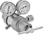
These valves automatically reduce a high inlet pressure from compressed gas tanks to a lower, stable outlet pressure. All have Compressed Gas Association (CGA) numbered inlet fittings for secure connections to compressed gas tanks. Choose a valve with the same CGA number as your tank and other system components. Valves have a gauge to monitor outlet pressure and a gauge to monitor inlet pressure from the tank.
Choose a valve with a maximum outlet pressure that’s approximately twice your application’s normal operating pressure. Your operating pressure should never exceed 75% of the valve’s maximum outlet pressure.
Single-stage valves reduce pressure in one step, which causes the outlet pressure to fluctuate slightly as you empty the tank. They’re best for applications where a constant outlet pressure isn’t critical.
Two-stage valves progressively reduce pressure over two steps for more consistent outlet pressure at all times. They’re often used in applications that require a constant outlet pressure regardless of the tank level.
Valves with a brass body have a longer service life than valves with a brass and steel body.
Valves with a stainless steel diaphragm can withstand harsh environments.
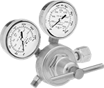
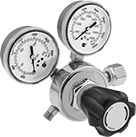
Inlet | Outlet | Material | ||||||||||
|---|---|---|---|---|---|---|---|---|---|---|---|---|
| CGA Number | Location | Thread Direction | Pressure Gauge Range, psi | Location | Thread Direction | Pressure Range, psi | Pressure Adjustment Method | Body | Seal | Diaphragm | Each | |
For Use With Oxygen | ||||||||||||
9/16"-18 UNF Male Outlet × NGO Female Inlet | ||||||||||||
| CGA 540 | Side | Right Hand | 0 to 4,000 | Side | Left Hand | 0 to 50 | Knob | Brass | PTFE | Neoprene | 00000000 | 0000000 |
| CGA 540 | Side | Right Hand | 0 to 4,000 | Side | Right Hand | 0 to 50 | T-Handle | Brass | PTFE | Neoprene | 00000000 | 000000 |
| CGA 540 | Side | Right Hand | 0 to 4,000 | Side | Right Hand | 0 to 50 | T-Handle | Brass | PTFE | Stainless Steel | 00000000 | 000000 |
| CGA 540 | Side | Right Hand | 0 to 4,000 | Side | Right Hand | 0 to 125 | T-Handle | Brass | PTFE | Rubber | 0000000 | 000000 |
| CGA 540 | Side | Right Hand | 0 to 4,000 | Side | Right Hand | 0 to 125 | T-Handle | Brass | PTFE | Stainless Steel | 0000000 | 000000 |
| CGA 540 | Side | Right Hand | 0 to 4,000 | Side | Right Hand | 0 to 145 | Knob | Brass/Steel | PTFE | Rubber | 0000000 | 000000 |
| CGA 540 | Side | Right Hand | 0 to 4,000 | Side | Right Hand | 0 to 200 | T-Handle | Brass | PTFE | Rubber | 000000 | 000000 |
| CGA 540 | Side | Right Hand | 0 to 4,000 | Side | Right Hand | 0 to 200 | T-Handle | Brass | PTFE | Stainless Steel | 00000000 | 000000 |
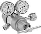
Inlet | Outlet | Material | ||||||||||
|---|---|---|---|---|---|---|---|---|---|---|---|---|
| CGA Number | Location | Thread Direction | Pressure Gauge Range, psi | Location | Thread Direction | Pressure Range, psi | Pressure Adjustment Method | Body | Seal | Diaphragm | Each | |
For Use With Oxygen | ||||||||||||
1/4 NPT Female Outlet × NGO Female Inlet | ||||||||||||
| CGA 540 | Side | Right Hand | 0 to 4,000 | Side | Right Hand | 0 to 250 | T-Handle | Brass | PTFE | Neoprene | 0000000 | 0000000 |
| CGA 540 | Side | Right Hand | 0 to 4,000 | Side | Right Hand | 0 to 250 | T-Handle | Brass | PTFE | Stainless Steel | 0000000 | 000000 |
9/16"-18 UNF Male Outlet × NGO Female Inlet | ||||||||||||
| CGA 540 | Side | Right Hand | 0 to 4,000 | Side | Right Hand | 0 to 50 | T-Handle | Brass | PTFE | Neoprene | 00000000 | 000000 |
| CGA 540 | Side | Right Hand | 0 to 4,000 | Side | Right Hand | 0 to 50 | T-Handle | Brass | PTFE | Stainless Steel | 00000000 | 000000 |
| CGA 540 | Side | Right Hand | 0 to 4,000 | Side | Right Hand | 0 to 125 | T-Handle | Brass | PTFE | Stainless Steel | 0000000 | 000000 |
| CGA 540 | Side | Right Hand | 0 to 4,000 | Side | Right Hand | 0 to 125 | T-Handle | Brass/Steel | PTFE | Rubber | 000000 | 000000 |
Tank-Mount High-Pressure-Regulating Valves for Air and Inert Gas
- For Use With: See Table
- Temperature Range: -20° to 120° F
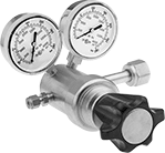
Often used for pressure-vessel testing and other high-pressure applications, these valves can handle at least seven times the outlet pressure of standard tank-mount pressure-regulating valves. They automatically reduce a high inlet pressure from compressed gas tanks to a lower, stable outlet pressure. All have Compressed Gas Association (CGA) numbered inlet fittings for secure connections to compressed gas tanks. Choose a valve with the same CGA number as your tank and other system components. Outlet fittings are Swagelok® for a leak-free seal around hard metal tubing in high-pressure lines. Also known as instrumentation fittings, Swagelok® fittings are compatible with Parker A-Lok, Gyrolok, Bilok, and Tylok fittings. Valves have a gauge to monitor outlet pressure and a gauge to monitor inlet pressure from the tank. They are single stage and reduce pressure in one step, which causes the outlet pressure to fluctuate slightly as you empty the tank.
Choose a valve with a maximum outlet pressure that’s approximately twice your application’s normal operating pressure. Your operating pressure should never exceed 75% of the valve’s maximum outlet pressure.
Inlet | Outlet | Material | ||||||||||||
|---|---|---|---|---|---|---|---|---|---|---|---|---|---|---|
| CGA Number | Location | Thread Direction | Pressure Gauge Range, psi | Stage | For Tube OD | Location | Pressure Range, psi | Pressure Adjustment Method | Shape | Body | Seal | Diaphragm | Each | |
NGO Female Inlet × Swagelok® Female Outlet | ||||||||||||||
| CGA 540 | Side | Right Hand | 0 to 4,000 | Single | 1/4" | Side | 0 to 1,500 | Knob | Straight | Brass | PCTFE | Neoprene | 0000000 | 0000000 |
| CGA 540 | Side | Right Hand | 0 to 4,000 | Single | 1/4" | Side | 0 to 2,500 | Knob | Straight | Brass | PCTFE | Neoprene | 0000000 | 000000 |
Tank-Mount Pressure-Regulating Valves for Cryogenic Cylinders
- For Use With: See Table
- Temperature Range: -20° to 120° F
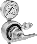
Automatically reduce a high inlet pressure from compressed gas tanks to a lower, stable outlet pressure. These valves can remove gases from liquid cryogenic cylinders. They have Compressed Gas Association (CGA) numbered inlet fittings for secure connections to compressed gas tanks. Choose a valve with the same CGA number as your tank and other system components. Valves come with a gauge to monitor outlet pressure. They are single stage and reduce pressure in one step, which causes the outlet pressure to fluctuate slightly as you empty the tank.
Choose a valve with a maximum outlet pressure that’s approximately twice your application’s normal operating pressure. Your operating pressure should never exceed 75% of the valve’s maximum outlet pressure.
Inlet | Outlet | ||||||||||
|---|---|---|---|---|---|---|---|---|---|---|---|
| For Use With | CGA Number | Location | Thread Direction | Stage | Thread Size | Location | Thread Direction | Pressure Range, psi | Pressure Adjustment Method | Each | |
UNF Male Outlet × NGO Female Inlet | |||||||||||
Brass Body—Stainless Steel Diaphragm and PTFE Seal | |||||||||||
| Oxygen | CGA 540 | Side | Right Hand | Single | 9/16"-18 | Bottom | Right Hand | 0 to 125 | T-Handle | 0000000 | 0000000 |


