


Filter by
For Relay Manufacturer
Electrical Connection
For Relay Manufacturer Model Number
Compatible Manufacturer Part Number
Export Control Classification Number (ECCN)
DFARS Specialty Metals
Relay Connection

Wire Connection


Certification
Relay Contacts
NEMA Contact Size | No. of Contacts | Compatible Mfr. Part No. | Each | |||
|---|---|---|---|---|---|---|
For Allen Bradley Series 500 | ||||||
| 0 | 1 | 40410-331-51 | 8064K21 | 000000 | ||
| 1 | 1 | 40410-331-52 | 8064K22 | 00000 | ||
| 2 | 1 | 40420-322-51 | 8064K23 | 00000 | ||
| 3 | 1 | 40430-300-51 | 8064K24 | 000000 | ||
| 4 | 1 | 40440-300-51 | 8064K25 | 000000 | ||
| 5 | 1 | 42450-805-01 | 8064K26 | 000000 | ||
For Allen Bradley Series K | ||||||
| 00 | 2 | Z-21101 | 8064K11 | 00000 | ||
| 00 | 3 | Z-21102 | 8064K12 | 00000 | ||
| 00 | 4 | Z-21103 | 8064K13 | 00000 | ||
| 0 | 1 | Z-34037 | 8064K14 | 00000 | ||
| 1 | 1 | Z-34038 | 8064K15 | 00000 | ||
| 2 | 1 | Z-34039 | 8064K16 | 00000 | ||
| 3 | 1 | Z-34040 | 8064K17 | 000000 | ||
| 4 | 1 | Z-34041 | 8064K18 | 000000 | ||
For Cutler-Hammer Series A1 | ||||||
| 1 | 3 | 6-23-2 | 8064K28 | 000000 | ||
| 1 | 4 | 6-23-3 | 8064K29 | 000000 | ||
| 2 | 3 | 6-24-2 | 8064K33 | 000000 | ||
| 3 | 3 | 6-25-2 | 8064K35 | 000000 | ||
| 4 | 3 | 6-26-2 | 8064K37 | 000000 | ||
| 5 | 3 | 6-27-2 | 8064K39 | 000000 | ||
For Cutler-Hammer Series B1 | ||||||
| 2 | 3 | 6-34-2 | 8064K42 | 000000 | ||
| 3 | 3 | 6-35-2 | 8064K46 | 000000 | ||
| 4 | 3 | 6-36-2 | 8064K48 | 000000 | ||
For Furnas 45 Series, Innova Series | ||||||
| 1 | 1 | 75DF14 | 8064K59 | 00000 | ||
| 1 3/4 | 1 | 75EF14 | 8064K61 | 00000 | ||
| 2 | 1 | 75FF14 | 8064K62 | 00000 | ||
| 2 1/2 | 1 | 75GF14 | 8064K63 | 000000 | ||
| 3 | 1 | 75HF14 | 8064K64 | 000000 | ||
| 3 1/2 | 1 | 75IF14 | 8064K65 | 000000 | ||
For General Electric 100 Series, 200 Series, and 300 Series | ||||||
| 0 | 4 | 546A300G002 | 8064K66 | 000000 | ||
| 1 | 4 | 546A301G002 | 8064K67 | 000000 | ||
| 2 | 3 | 546A780G002 | 8064K68 | 000000 | ||
| 3 | 3 | 55153677G002 | 8064K69 | 000000 | ||
| 4 | 3 | 55153678G002 | 8064K71 | 000000 | ||
For Square D Class 9998 | ||||||
| 1, 1P | 3 | SL-3 | 8064K81 | 000000 | ||
| 2 | 3 | SL-4 | 8064K83 | 000000 | ||
| 3 | 3 | SL-7 | 8064K86 | 000000 | ||
| 4 | 3 | SL-9 | 8064K88 | 000000 | ||
For Westinghouse A200 Series, N Series, and NF Series | ||||||
| 00 | 4 | 373B331G18 | 8064K92 | 000000 | ||
| 0 | 4 | 373B331G04 | 8064K93 | 000000 | ||
| 1 | 3 | 1605212 | 8064K95 | 000000 | ||
| 1 | 4 | 373B331G09 | 8064K96 | 000000 | ||
| 2 | 3 | 373B331G12 | 8064K98 | 000000 | ||
| 3 | 3 | 626B187G13 | 8064K104 | 000000 | ||
| 4 | 3 | 626B187G17 | 8064K108 | 000000 | ||
| 5 | 1 | 477B477G05 | 8064K111 | 000000 | ||
| 5 | 3 | 1620146 | 8064K113 | 000000 | ||
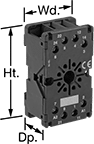
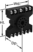
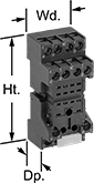
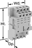
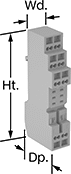
Relay Sockets
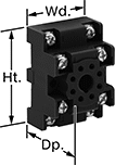 | 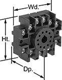 |  |  | 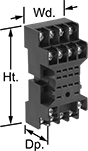 |
Style A | Style B | Style C | Style D | Style E |
 | 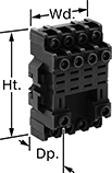 | 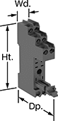 |  |  |
Style F | Style G | Style H | Style J | Style K |
Sockets | Hold-Down Clips | ||||||||||||||
|---|---|---|---|---|---|---|---|---|---|---|---|---|---|---|---|
Style | No. of Terminals | For Quick-Disconnect Tab Wd. | For Switching Current @ Voltage | For Max. Switching Voltage, V AC | Ht. | Wd. | Dp. | Features | Each | Pkg. Qty. | Pkg. | ||||
Circular-Pin-Terminal Relay Connection | |||||||||||||||
Screw-Terminal Wire Connection | |||||||||||||||
| A | 8 | — | 10 amp @ 300V AC | 300 | 2" | 1.4" | 1.1" | — | 7122K17 | 00000 | 1 | 7122K68 | 00000 | ||
| A | 8 | — | 10 amp @ 600V AC | 600 | 2" | 1.6" | 1" | — | 7122K19 | 0000 | — | ——— | 0 | ||
| B | 11 | — | 10 amp @ 300V AC | 300 | 2" | 2.3" | 1" | — | 7122K21 | 0000 | — | ——— | 0 | ||
| C | 8 | — | 10 amp @ 300V AC | 300 | 2.6" | 1.5" | 1.1" | Recessed Terminals | 7122K11 | 00000 | 1 | 7122K62 | 0000 | ||
| C | 11 | — | 10 amp @ 300V AC | 300 | 2.6" | 1.5" | 1.1" | Recessed Terminals | 7122K12 | 00000 | 1 | 7122K62 | 0000 | ||
| D | 11 | — | 10 amp @ 300V AC | 300 | 2.4" | 2.3" | 0.9" | — | 7122K18 | 0000 | 1 | 7122K65 | 0000 | ||
Quick-Disconnect-Terminal Relay Connection | |||||||||||||||
Screw-Terminal Wire Connection | |||||||||||||||
| E | 8 | 0.187" | 10 amp @ 300V AC | 300 | 2.6" | 1.2" | 1" | — | 7122K22 | 00000 | 1 | 7122K61 | 0000 | ||
| E | 8 | 0.197" | 15 amp @ 120V AC | 250 | 3.1" | 1.2" | 1.3" | Recessed Terminals | 69585K5 | 00000 | — | ——— | 0 | ||
| E | 11 | 0.187" | 10 amp @ 240V AC | 250 | 3.1" | 1.9" | 1" | — | 7266K17 | 00000 | — | ——— | 0 | ||
| E | 11 | 0.2" | 10 amp @ 240V AC | 240 | 3.1" | 1.5" | 1.2" | — | 7122K23 | 00000 | 2 | 7122K69 | 0000 | ||
| E | 14 | 0.11" | 10 amp @ 300V AC | 300 | 2.5" | 1.2" | 1" | — | 7122K25 | 00000 | 1 | 7122K61 | 0000 | ||
| E | 14 | 0.2" | 12 amp @ 240V AC | 240 | 3.1" | 1.8" | 1.3" | Recessed Terminals | 7122K24 | 00000 | 2 | 7122K69 | 0000 | ||
| F | 14 | 0.11" | 10 amp @ 300V AC | 300 | 2.6" | 1.2" | 1.1" | Recessed Terminals | 7122K16 | 00000 | 1 | 7122K63 | 0000 | ||
| G | 8 | 0.197" | 10 amp @ 300V AC | 300 | 2.7" | 1.2" | 1.2" | Recessed Terminals | 7122K13 | 0000 | 1 | 7122K66 | 0000 | ||
| G | 11 | 0.197" | 10 amp @ 300V AC | 300 | 2.7" | 1.6" | 1.2" | Recessed Terminals | 7122K14 | 0000 | 1 | 7122K67 | 0000 | ||
| G | 14 | 0.197" | 10 amp @ 300V AC | 300 | 2.7" | 2" | 1.2" | Recessed Terminals | 7122K15 | 00000 | 1 | 7122K88 | 0000 | ||
| H | 5 | 0.187" | 10 amp @ 120V AC | 380 | 3.1" | 0.6" | 2.4" | Recessed Terminals | 7098K21 | 0000 | — | ——— | 0 | ||
| H | 8 | 0.098" | 5 amp @ 120V AC | 380 | 3.1" | 0.6" | 2.4" | Recessed Terminals | 7098K22 | 00000 | — | ——— | 0 | ||
| J | 8 | 0.187" | 15 amp @ 120V AC | 300 | 3.1" | 1.2" | 1.3" | Recessed Terminals | 69585K1 | 0000 | — | ——— | 0 | ||
| J | 11 | 0.187" | 15 amp @ 120V AC | 300 | 3.1" | 1.6" | 1.2" | Recessed Terminals | 69585K2 | 00000 | — | ——— | 0 | ||
| J | 14 | 0.11" | 10 amp @ 250V AC | 250 | 3.1" | 1.2" | 1.6" | Recessed Terminals | 69585K611 | 0000 | — | ——— | 0 | ||
| J | 14 | 0.11" | 10 amp @ 300V AC | 300 | 3.1" | 1.2" | 1.6" | Recessed Terminals | 69585K6 | 0000 | — | ——— | 0 | ||
| J | 14 | 0.187" | 15 amp @ 120V AC | 300 | 3.1" | 2" | 1.2" | Recessed Terminals | 69585K3 | 00000 | — | ——— | 0 | ||
Spring-Clamp-Terminal Wire Connection | |||||||||||||||
| K | 5 | 0.187" | 10 amp @ 120V AC | 380 | 3.6" | 0.71" | 1.5" | — | 7098K23 | 0000 | — | ——— | 0 | ||
| K | 8 | 0.098" | 5 amp @ 120V AC | 380 | 3.6" | 0.71" | 1.5" | — | 7098K24 | 00000 | — | ——— | 0 | ||
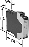
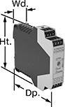
Safety Relays with Diagnostic Capabilities
 |  |
Relay | Relay with Time Delay |
Control and diagnose issues with safety-critical circuits. These relays have a microprocessor that monitors safety components, such as emergency stops and light curtains, and sends a signal to stop the operation if a failure is detected and restart when the issue is resolved. They also help with diagnostic tasks because of their feedback circuit, which allows basic relays to communicate their status back to the safety relay. These relays have a duplicate set of input and output signals, so they’ll still stop the controlled device if one of the inputs fails.
IP20 rated, they have recessed terminals which prevent fingers and other objects from touching live circuits. These relays have been tested to multiple safety standards and can help achieve PL, SIL, or CAT system ratings. They also meet ISO and IEC standards for machine safety.
Mount them to 35 mm DIN rail (also known as DIN 3 Rail) for fast installation.
Time Delay—Relays with delayed safety outputs are often used where power must be maintained after an input signal is received. For example, after a stop button for a machine is pressed, the guard door will stay locked until the machine cycle is finished.
No. of Terminals | Input Voltage | Switching Current @ Voltage | Max. Switching Voltage | Ht. | Wd. | Dp. | For Use With | Mounting Location | Max. System Safety Rating | Features | Each | |||
|---|---|---|---|---|---|---|---|---|---|---|---|---|---|---|
2 Circuits Controlled | ||||||||||||||
2 Safety Outputs with 2 Off and 2 Delayed Safety Outputs with 2 Off | ||||||||||||||
| 16 | 24V DC | 3 amp @ 240V AC 3 amp @ 24V DC | 250V AC, 250V DC | 3.9" | 0.9" | 4.5" | Emergency Stops, Safety Light Curtains | DIN Rail | PLe, SIL 3 | Time Delay | 6322N15 | 0000000 | ||
2 Safety Outputs with 2 Off and 1 Signal Output with 2 On | ||||||||||||||
| 16 | 24V AC, 24V DC | 5 amp @ 240V AC 5 amp @ 24V DC | 250V AC, 250V DC | 3.9" | 0.9" | 4.5" | Two-Hand Switches | DIN Rail | PLe, SIL 3 | — | 6322N16 | 000000 | ||
3 Safety Outputs with 2 Off and 1 Signal Output with 2 On | ||||||||||||||
| 16 | 240V AC | 3 amp @ 240V AC 2.5 amp @ 24V DC | 250V AC, 250V DC | 3.9" | 1.8" | 4.5" | Emergency Stops | DIN Rail | PLe, SIL 3 | — | 6322N13 | 000000 | ||
| 24 | 24V AC, 48V AC, 120V AC, 240V AC, 24V DC, 48V DC, 60V DC, 120V DC, 240V DC | 5 amp @ 240V AC 5 amp @ 24V DC | 250V AC, 250V DC | 4.42" | 0.9" | 4.5" | Emergency Stops | DIN Rail | PLe, SIL 3 | — | 6322N14 | 00000000 | ||
3 Circuits Controlled | ||||||||||||||
3 Safety Outputs with 2 Off and 1 Signal Output with 2 On | ||||||||||||||
| 16 | 24V DC | 4 amp @ 230V AC 4 amp @ 24V DC | 240V AC | 3.9" | 0.9" | 4.5" | Emergency Stops | DIN Rail | PLe, SIL 3 | — | 6322N19 | 000000 | ||
 |  |
Auxiliary Contact Block | Auxiliary Contact Block with Time Delay |
No. of Terminals | Input Voltage, V DC | Switching Current @ Voltage | Max. Switching Voltage | Ht. | Wd. | Dp. | Features | Each | |||
|---|---|---|---|---|---|---|---|---|---|---|---|
5 Safety Outputs | |||||||||||
| 16 | 24 | 3 amp @ 240V AC 2.5 amp @ 24V DC | 250V AC, 250V DC | 3.9" | 0.9" | 4.5" | — | 6322N22 | 0000000 | ||
4 Delayed Safety Outputs | |||||||||||
| 16 | 24 | 3 amp @ 240V AC 3 amp @ 24V DC | 250V AC, 250V DC | 3.9" | 0.9" | 4.5" | Time Delay | 6322N18 | 000000 | ||
