


Compact Spade-Terminal Relays
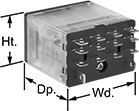

Fit these relays where standard spade-terminal relays are too big. You can connect them three ways. Plug them into a socket (sold separately), connect them with quick-disconnect terminals, or solder wires directly to the terminals. An LED indicator shows you the status of the relay, so you know it’s connected and wired correctly.
Relays that control 2 or more circuits have a lockable test button, so you can test their function. When you press the button, the relay switches contacts. Use this button when checking a relay for proper function before installing it, or when investigating issues with wired relays.
Relay sockets mount directly on 35 mm DIN rail (also known as DIN 3 rail) for fast installation. You can also mount them to a flat surface using screws.
![]() For technical drawings and 3-D models, click on a part number.
For technical drawings and 3-D models, click on a part number.
Relays | Relay Sockets with Screw Terminals | |||||||||||
|---|---|---|---|---|---|---|---|---|---|---|---|---|
| Number of Terminals | Input Voltage | Control Current, mA | Switching Current @ Voltage | Maximum Switching Voltage | Ht. | Wd. | Dp. | Quick-Disconnect Tab Wd. | Each | Each | ||
4 Circuits Controlled with 4 Off (Normally Open) or 4 On (Normally Closed)—4PDT | ||||||||||||
Relay-Socket Mount | ||||||||||||
| 14 | 12V DC | 125 | 15 A @ 120 V AC 12 A @ 24 V DC | 300V AC | 1.1" | 1.6" | 1.6" | 0.187" | 00000000 | 000000 | 0000000 | 000000 |
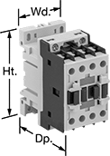
DIN-Rail Mount Touch-Safe Screw Terminal Relays
Quickly and safely mount these relays on 35 mm DIN rail (also known as DIN 3). IP20 rated, they have recessed terminals that prevent fingers and other objects from touching live circuits.
Relays that control 3 and 4 circuits are built to IEC dimensional standards and are often called IEC contactors. Auxiliary contacts (sold separately) allow you to add a signaling device or control another relay. You can add one auxiliary contact to all of these relays. For relays with 12 terminals, you can add two side-mount auxiliary contacts.
Use replacement coils to swap out a broken coil or change the input voltage of a relay. They are only compatible with relays that have 12 terminals. The full load current of the relay must match the full load current range of the coil.
Control | |||||||||
|---|---|---|---|---|---|---|---|---|---|
| Number of Terminals | Input Voltage | Current, mA | Switching Current @ Voltage (Load Type) | Max. Switching Voltage | Ht. | Wd. | Dp. | Each | |
4 Circuits Controlled with 4 Off (Normally Open)—4PST-NO | |||||||||
| 10 | 24V AC | 125 | 10 A @ 600 V AC | 600 V AC | 2.3" | 1.7" | 2.2" | 00000000 | 000000 |

| Number of Circuits Controlled | For Relay Width | Switch Starting Position | Industry Designation | Mounting Location | Each | |
| 2 | 1.7" | 1 Off (Normally Open) and 1 On (Normally Closed) | DPST-1NO/1NC | Front | 00000000 | 000000 |
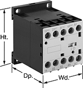
Machine-Guard Relays
The interlocked opposing contacts won't close at the same time, so these relays are suitable for safety applications such as machine guarding. The screw terminals are recessed to prevent accidental contact with live connections. Mount them on 35 mm DIN rail (also known as DIN 3 rail) or flat surfaces. These relays are built to IEC dimensional standards.
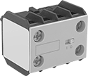
Auxiliary contact (sold separately) allows you to add a signaling device or control another relay.
| Number of Terminals | Input Voltage | Control Current, mA | Switching Current @ 600V AC | Max. Switching Voltage | Ht. | Wd. | Dp. | Each | |
4 Circuits Controlled with 2 Off (Normally Open) and 2 On (Normally Closed)—4PST-2NO/2NC | |||||||||
|---|---|---|---|---|---|---|---|---|---|
| 10 | 24V AC | 125 | 10A | 600V AC | 2.3" | 1.7" | 2.2" | 00000000 | 000000 |
4 Circuits Controlled with 3 Off (Normally Open) and 1 On (Normally Closed)—4PST-3NO/1NC | |||||||||
| 10 | 24V AC | 125 | 10A | 600V AC | 2.3" | 1.7" | 2.2" | 00000000 | 00000 |
| Number of Circuits Controlled | Switch Starting Position | Industry Designation | Mounting Location | For Relay Width | Each | |
| 2 | 1 Off (Normally Open) and 1 On (Normally Closed) | DPST-1NO/1NC | Front | 1.7" | 00000000 | 000000 |