


Filter by
Wire Connection


Mounting Location
Operation Type
Switching Voltage
Control Current


Timer Function
Timing Adjustment Style

Switch Starting Position
Overall Timing
Switch Action
U.S.–Mexico–Canada Agreement (USMCA) Qualifying
Mechanical Life Cycles
Export Control Classification Number (ECCN)
REACH
RoHS
DFARS Specialty Metals
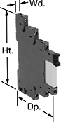
DIN-Rail Mount Interface Relays
1 Circuit Controlled with 1 Off or 1 On—SPDT
 | 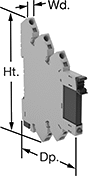 |
With Screw Terminals | With Spring-Clamp Terminals |
Interface Relays | Replacement Relays | |||||||||||||
|---|---|---|---|---|---|---|---|---|---|---|---|---|---|---|
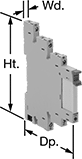
No. of Terminals | Input Voltage | Control Current, mA | Switching Current @ Voltage | Max. Switching Voltage, V AC | Ht. | Wd. | Dp. | Features | Each | Each | ||||
With Screw Terminals | ||||||||||||||
| 5 | 12V AC, 12V DC | 16 | 6 amp @ 240V AC | 250 | 3.5" | 0.2" | 3" | LED Indicator | 8262T14 | 000000 | 8262T15 | 00000 | ||
With Spring-Clamp Terminals | ||||||||||||||
| 5 | 12V AC, 12V DC | 16 | 6 amp @ 240V AC | 250 | 3.7" | 0.2" | 3" | LED Indicator | 4144N15 | 00000 | 8262T15 | 0000 | ||
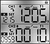
Dual-Channel DIN-Rail Mount Multifunction Timer Relays
 |  |
Timing Range | |||||||||||||||
|---|---|---|---|---|---|---|---|---|---|---|---|---|---|---|---|
No. of Terminals | Input Voltage | Control Current, mA | Timer Relay Function | No. of | Overall | Switching Current @ Voltage | Max. Switching Voltage, V AC | Ht. | Wd. | Dp. | Features | Each | |||
2 Circuits Controlled with 2 Off and 2 On—DPDT | |||||||||||||||
| 12 | 120V AC, 240V AC, 110V DC, 240V DC | 16 | Manual Switch Control Fixed On/Off Switch on (Single Shot) Delayed Start (Delay on Make) Delayed Switch Off (Delay on Break) Delayed Switch-On with Delayed Switch-Off Interval Repeat Cycle Asymmetrical Repeat Cycle Switch-On Asymmetrical Repeat Cycle | 30 | 0.1 sec. to 9,999 hr. | 16 amp @ 240V AC | 240 | 3.4" | 1.4" | 2.2" | 2 Individually Programmable Timers, LCD Screen | 7105N12 | 0000000 | ||
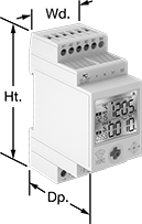
DIN-Rail Mount Multifunction Interface Timer Relays
 |
Protect components from voltage spikes while amplifying the relay’s signal and reducing interference for reliable transmission—these relays interface between your controller and system components to isolate the input and output circuits. They are often used for switching applications, such as small motors and pilot lights. These relays provide a variety of timing functions in one relay. The included relay socket mounts on 35 mm DIN rail (also known as DIN 3 rail) for fast installation. Relays disconnect from the socket for easy replacement.
Timer Relays | Replacement Relays | |||||||||||||||
|---|---|---|---|---|---|---|---|---|---|---|---|---|---|---|---|---|
Timing Range | ||||||||||||||||
No. of Terminals | Input Voltage | Control Current, mA | Timer Relay Function | No. of | Overall | Switching Current @ Voltage | Max. Switching Voltage, V AC | Ht. | Wd. | Dp. | Each | Each | ||||
1 Circuit Controlled with 1 Off or 1 On—SPDT | ||||||||||||||||
| 5 | 24V AC, 24V DC | 16 | Delayed Start (Delay on Make) Interval Repeat Cycle | 4 | 0.1 sec. to 6 hr. | 6 amp @ 240V AC | 240 | 3 1/2" | 0.2" | 2.8" | 4799T11 | 000000 | 8262T21 | 00000 | ||
