


Filter by
System of Measurement
Input Voltage
Switch Designation
Number of Circuits Controlled
Horsepower @ Switching Voltage
Socket Connection
Number of Terminals
Mounting Location
Switch Action
Relay Type

Switch Starting Position
Electrical Connection
Electrical Phase
Operation Type
Certification
Quick-Disconnect Tab Width
Mechanical Life Cycles
Control Current
U.S.–Mexico–Canada Agreement (USMCA) Qualifying
DFARS Specialty Metals
Export Control Classification Number (ECCN)
RoHS
Compact Spade-Terminal Relays
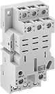 |  | 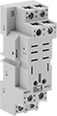 |
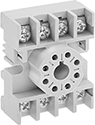
11-Terminal Relay Socket | 14-Terminal Relay Socket | 8-Terminal Relay Socket |
Fit these relays where standard spade-terminal relays are too big. You can connect them three ways. Plug them into a socket (sold separately), connect them with quick-disconnect terminals, or solder wires directly to the terminals. An LED indicator shows you the status of the relay, so you know it’s connected and wired correctly.
2 Circuits Controlled—Relays that control 2 or more circuits have a lockable test button, so you can test their function. When you press the button, the relay switches contacts. Use this button when checking a relay for proper function before installing it, or when investigating issues with wired relays.
Sockets with Screw Terminals—Relay sockets mount directly on 35 mm DIN rail (also known as DIN 3 rail) for fast installation. You can also mount them to a flat surface using screws.
Relays | Sockets with Screw Terminals | |||||||||||||||
|---|---|---|---|---|---|---|---|---|---|---|---|---|---|---|---|---|
No. of Terminals | Input Voltage, V DC | Control Current, mA | Switching Current @ Voltage | Max. Switching Voltage, V AC | hp @ Switching Voltage | Ht. | Wd. | Dp. | Quick-Disconnect Tab Wd. | Features | Each | Each | ||||
2 Circuits Controlled with 2 Off or 2 On—DPDT | ||||||||||||||||
Relay-Socket Mount | ||||||||||||||||
| 8 | 24 | 38 | 15 amp @ 120V AC 12 amp @ 24V DC | 300 | 1/2 hp @ 120V AC 1 hp @ 277V AC | 1.1" | 0.9" | 1.6" | 0.187" | LED Indicator, Lockable Test Button, Mechanical Flag Indicator | 69585K67 | 000000 | 69585K1 | 00000 | ||
Safety Relays
SIL 2, PLd Max. System Safety Rating—DIN-Rail Mount
 |
Relays that meet SIL 2 are tested for applications with a probability of failure of 0.1% to 1%. They’re often used for emergency shutdowns, and fire, gas, and overpressure detection.
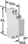
No. of Terminals | Input Voltage, V DC | Control Current, mA | Switching Current @ Voltage | Max. Switching Voltage, V AC | Ht. | Wd. | Dp. | Features | Each | |||
|---|---|---|---|---|---|---|---|---|---|---|---|---|
Screw-Terminal Wire Connection | ||||||||||||
2 Circuits Controlled with 1 Off and 1 On—DPST-1NO/1NC | ||||||||||||
| 8 | 24 | 38 | 6 amp @ 240V AC | 250 | 3.4" | 0.9" | 3.9" | Interlocked Opposing Contacts, LED Indicator, Recessed Terminals | 6242N113 | 000000 | ||
Hazardous Location Relays
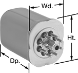 |  |
Circular-Pin Terminals—Hermetically Sealed | Sockets with Screw Terminals |
Sealed for safety, these relays are a good choice for hazardous locations where combustible or corrosive gases may be present.
Circular-Pin Terminal—Relays with circular-pin terminals or quick-disconnect terminals are hermetically sealed—completely air- and watertight—to shield internal parts from gases, moisture, and other contaminants. They plug into relay sockets (sold separately) for easy installation.
Sockets with Screw Terminals—Relay sockets mount to 35 mm DIN rail (also known as DIN 3 rail) or flat surfaces.
Relays | Sockets with Screw Terminals | ||||||||||||||
|---|---|---|---|---|---|---|---|---|---|---|---|---|---|---|---|
No. of Terminals | Input Voltage, V DC | Control Current, mA | Switching Current @ Voltage | Max. Switching Voltage, V AC | hp @ Switching Voltage | Ht. | Wd. | Dp. | Hazardous Location Rating | Each | Each | ||||
Circular-Pin Terminals—Hermetically Sealed | |||||||||||||||
2 Circuits Controlled with 2 Off or 2 On—DPDT | |||||||||||||||
| 8 | 24 | 38 | 12 amp @ 120V AC/24V DC | 300 | 1/3 hp @ 120V AC | 1.6" | 1.4" | 2.1" | NEC Class I Division 2 Groups A, B, C, D | 7125T34 | 0000000 | 7125T41 | 00000 | ||
