


Filter by
System of Measurement
Switching Voltage
Mounting Location
Overall Timing


Operation Type
Control Current
Horsepower @ Switching Voltage
Timer Function
Socket Connection
Switch Starting Position
Electrical Connection
DFARS Specialty Metals
Export Control Classification Number (ECCN)
Thin Spade-Terminal Relays
 |  |  |  |
5-Terminal Relay | 8-Terminal Relay | Sockets with Spring-Clamp Terminals | Sockets with Screw Terminals |
Relays | Sockets with Screw Terminals | Sockets with Spring-Clamp Terminals | |||||||||||||||
|---|---|---|---|---|---|---|---|---|---|---|---|---|---|---|---|---|---|
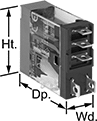
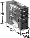
No. of Terminals | Input Voltage, V AC | Control Current, mA | Switching Current @ Voltage | Max. Switching Voltage, V AC | hp @ Switching Voltage | Ht. | Wd. | Dp. | Quick-Disconnect Tab Wd. | Each | Each | Each | |||||
1 Circuit Controlled with 1 Off or 1 On—SPDT | |||||||||||||||||
Relay-Socket Mount | |||||||||||||||||
| 5 | 240 | 4 | 10 amp @ 120V AC/24V DC | 380 | 1/3 hp @ 120V AC | 1.1" | 0.5" | 1.4" | 0.187" | 7098K13 | 000000 | 7098K21 | 00000 | 7098K23 | 00000 | ||
2 Circuits Controlled with 2 Off or 2 On—DPDT | |||||||||||||||||
Relay-Socket Mount | |||||||||||||||||
| 8 | 240 | 4 | 5 amp @ 120V AC/24V DC | 380 | 1/6 hp @ 120V AC | 1.1" | 0.5" | 1.4" | 0.098" | 7098K16 | 00000 | 7098K22 | 00000 | 7098K24 | 00000 | ||
Hazardous Location Relays
 |  |
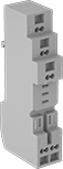
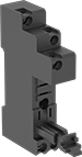
Screw Terminals | Spring-Clamp Terminals |
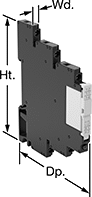
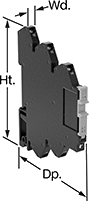
Sealed for safety, these relays are a good choice for hazardous locations where combustible or corrosive gases may be present.
Screw Terminals—Relays with screw terminals are considered interface relays, so they’re placed between your controller and components to isolate the input and output circuits. This means they protect your component from voltage spikes while amplifying the relay’s signal and reducing interference for reliable transmission. They are often used for switching applications, such as small motors and pilot lights. The included relay socket mounts on 35 mm DIN rail (also known as DIN 3 rail).
Spring-Clamp Terminals—Relays with spring-clamp terminals are considered interface relays, so they’re placed between your controller and components to isolate the input and output circuits. This means they protect your component from voltage spikes while amplifying the relay’s signal and reducing interference for reliable transmission. They are often used for switching applications, such as small motors and pilot lights. The included relay socket mounts on 35 mm DIN rail (also known as DIN 3 rail). Relays with spring-clamp terminals connect and disconnect to wires without needing to turn screws. With no screws to shake loose with vibration, the terminals hold tight over time.
No. of Terminals | Input Voltage | Control Current, mA | Switching Current @ Voltage | Max. Switching Voltage | Ht. | Wd. | Dp. | Enclosure Rating | Hazardous Location Rating | Each | |||
|---|---|---|---|---|---|---|---|---|---|---|---|---|---|
Screw Terminals | |||||||||||||
1 Circuit Controlled with 1 Off or 1 On—SPDT | |||||||||||||
| 5 | 48V AC, 48V DC | 4 | 6 amp @ 240V AC/30V DC | 400V AC/125V DC | 3.5" | 0.2" | 2.9" | IP20 | NEC Class I Division 2 Groups A, B, C, D | 4190N12 | 000000 | ||
| 5 | 48V AC, 48V DC | 4 | 16 amp @ 240V AC/24V DC | 400V AC/300V DC | 3.5" | 0.6" | 2.9" | IP20 | NEC Class I Division 2 Groups A, B, C, D | 4190N17 | 00000 | ||
2 Circuits Controlled with 2 Off or 2 On—DPDT | |||||||||||||
| 8 | 48V AC, 48V DC | 4 | 8 amp @ 240V AC/24V DC | 400V AC/300V DC | 3.5" | 0.6" | 2.9" | IP20 | NEC Class I Division 2 Groups A, B, C, D | 4190N18 | 00000 | ||
Spring-Clamp Terminals | |||||||||||||
1 Circuit Controlled with 1 Off or 1 On—SPDT | |||||||||||||
| 5 | 120V AC, 120V DC | 4 | 12 amp @ 240V AC/24V DC | 400V AC/300V DC | 2.9" | 0.6" | 3.7" | IP20 | NEC Class I Division 2 Groups A, B, C, D | 8163N16 | 00000 | ||
Solid State Surface-Mount Timer Relays
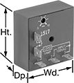 |
Attach these relays to a flat surface using the mounting hole. They have no moving parts, so compared to mechanical switches, they require less maintenance, last longer, and are quieter.
Delayed Start (Delay on Make)—Delayed start (delay on make) relays allow you to set how long it takes for the relay to turn on after input voltage is applied. For example, a drill starts pumping a lubricant immediately, but it does not start rotating until the set time has elapsed.
Potentiometer—Switches with a potentiometer (variable switch) allow you to adjust the delay within the range.
Timing Range | |||||||||||||
|---|---|---|---|---|---|---|---|---|---|---|---|---|---|
No. of Terminals | Input Voltage | Control Current, mA | No. of | Overall | Switching Current @ Voltage | Ht. | Wd. | Dp. | Features | Each | |||
Delayed Start (Delay on Make) | |||||||||||||
1 Circuit Controlled with 1 Off—SPST-NO | |||||||||||||
| 2 | 120V AC, 120V DC | 4 | 1 | 0.05 sec. to 1 sec. | 1 amp @ 120V AC | 2" | 2" | 0.89" | Potentiometer | 77055K25 | 0000000 | ||
| 2 | 120V AC, 120V DC | 4 | 1 | 0.25 sec. to 5 sec. | 1 amp @ 120V AC | 2" | 2" | 0.89" | Potentiometer | 77055K26 | 000000 | ||
| 2 | 120V AC, 120V DC | 4 | 1 | 0.5 sec. to 10 sec. | 1 amp @ 120V AC | 2" | 2" | 0.89" | Potentiometer | 77055K27 | 000000 | ||
| 2 | 120V AC, 120V DC | 4 | 1 | 3 sec. to 60 sec. | 1 amp @ 120V AC | 2" | 2" | 0.89" | Potentiometer | 77055K28 | 000000 | ||
| 2 | 120V AC, 120V DC | 4 | 1 | 15 sec. to 300 sec. | 1 amp @ 120V AC | 2" | 2" | 0.89" | Potentiometer | 77055K29 | 000000 | ||
| 2 | 120V AC, 120V DC | 4 | 1 | 30 sec. to 10 min. | 1 amp @ 120V AC | 2" | 2" | 0.89" | Potentiometer | 77055K31 | 000000 | ||
