


About Timer Relays
More
DIN-Rail Mount Interface Relays
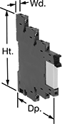
Isolate input and output circuits to prevent damage from voltage spikes, reduce signal interference, and amplify signal. These relays interface between your controller and components—they receive a signal from the controller to switch power on or off to the components. All have an LED indicator that shows you if your switch is actuated, so you know it’s connected and wired correctly. Use them to communicate signals to devices like motors or sensors. Mount them on 35 mm DIN rail (also known as DIN 3 rail).
Relays with Relay Sockets | Replacement Relays | |||||||||||
|---|---|---|---|---|---|---|---|---|---|---|---|---|
| Number of Terminals | Input Voltage | Control Current, mA | Switching Current @ 240V AC | hp @ Switching Voltage | Ht. | Wd. | Dp. | Features | Each | Each | ||
1 Circuit Controlled with 1 Off (Normally Open) or 1 On (Normally Closed)—SPDT | ||||||||||||
With Screw Terminals | ||||||||||||
| 5 | 12V DC | 41 | 16A | 1/4 hp @ 120 V AC | 3.5" | 0.6" | 3" | LED Indicator | 0000000 | 000000 | 0000000 | 00000 |
Circuit Board Safety Relays
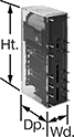
Reduce connection errors on circuit boards that control machine guards and other safety devices. Also known as force-guided contact relays, they have contact pairs that won’t close at the same time, even if contacts stick or weld shut. These relays take up less space on a board than those with electrical wiring because their solder pin terminals mount directly through circuit board holes. Use them to control high-power components, such as fans and heaters, from a low-power circuit.
| Number of Terminals | Input Voltage | Control Current, mA | Switching Current @ Voltage | Max. Switching Voltage | Mechanical Life Cycles | Ht. | Wd. | Dp. | Pin Lg. | Features | Each | |
6 Circuits Controlled with 3 Off (Normally Open) and 3 On (Normally Closed)—6PST-3NO/3NC | ||||||||||||
|---|---|---|---|---|---|---|---|---|---|---|---|---|
| 14 | 12V DC | 41 | 6 A @ 240 V AC/30 V DC | 250V AC, 125V DC | 10,000,000 | 2" | 0.5" | 1" | 0.14" | Interlocked Opposing Contacts | 0000000 | 000000 |
6 Circuits Controlled with 4 Off (Normally Open) and 2 On (Normally Closed)—6PST-4NO/2NC | ||||||||||||
| 14 | 12V DC | 41 | 6 A @ 240 V AC/30 V DC | 250V AC, 125V DC | 10,000,000 | 2" | 0.5" | 1" | 0.14" | Interlocked Opposing Contacts | 0000000 | 00000 |
6 Circuits Controlled with 5 Off (Normally Open) and 1 On (Normally Closed)—6PST-5NO/1NC | ||||||||||||
| 14 | 12V DC | 41 | 6 A @ 240 V AC/30 V DC | 250V AC, 125V DC | 10,000,000 | 2" | 0.5" | 1" | 0.14" | Interlocked Opposing Contacts | 0000000 | 00000 |
Solid State Surface-Mount Timer Relays
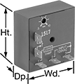
Attach these relays to a flat surface using the mounting hole. They have no moving parts, so compared to mechanical switches, they require less maintenance, last longer, and are quieter.
Delayed start (delay-on-make) relays allow you to set how long it takes for the relay to turn on after input voltage is applied. For example, a drill starts pumping a lubricant immediately, but it does not start rotating until the set time has elapsed.
Delayed switch-off (delay-on-break) relays activate with a switch instead of input voltage. When the switch is turned off, the relay remains on for a programmed amount of time before turning off. For example, a projector’s light is turned off with a switch, but its cooling fan continues to run for a set time.
Interval relays use input voltage to turn on for a programmed amount of time. For example, when a part moving down a conveyor reaches a certain location, a cleaning spray comes on for a set time.
Repeat cycle relays turn on for a duration, then off for the same duration. They alternate between the two cycles until input voltage is removed. A common example would be a flashing light.
Switch-on (single-shot) relays require a switch to activate the relay. They’ll stay on for a programmed amount of time. For example, lights in a storage room are turned on with a switch and stay on for a set time before turning off.
Timing Range | ||||||||||||
|---|---|---|---|---|---|---|---|---|---|---|---|---|
| Number of Terminals | Input Voltage | Control Current, mA | No. of | Overall | Switching Current @ Voltage | Max. Switching Voltage | hp @ Switching Voltage | Ht. | Wd. | Dp. | Each | |
Delayed Start (Delay-on-Make) | ||||||||||||
1 Circuit Controlled with 1 Off (Normally Open) or 1 On (Normally Closed)—SPDT | ||||||||||||
| 5 | 24V DC | 41 | 1 | 0.1 sec.-10 sec. | 30 A @ 240 V AC/24 V DC | 240V AC | 1 hp @ 120 V AC 2 hp @ 240 V AC | 3" | 2" | 1.4" | 00000000 | 000000 |
| 5 | 24V DC | 41 | 1 | 0.1 min.-10 min. | 30 A @ 240 V AC/24 V DC | 240V AC | 1 hp @ 120 V AC 2 hp @ 240 V AC | 3" | 2" | 1.4" | 00000000 | 00000 |
| 5 | 24V DC | 41 | 1 | 1 min.-100 min. | 30 A @ 240 V AC/24 V DC | 240V AC | 1 hp @ 120 V AC 2 hp @ 240 V AC | 3" | 2" | 1.4" | 00000000 | 00000 |
Delayed Switch-Off (Delay-on-Break) | ||||||||||||
1 Circuit Controlled with 1 Off (Normally Open) or 1 On (Normally Closed)—SPDT | ||||||||||||
| 6 | 24V DC | 41 | 1 | 0.1 sec.-10 sec. | 30 A @ 240 V AC/24 V DC | 240V AC | 1 hp @ 120 V AC 2 hp @ 240 V AC | 3" | 2" | 1.4" | 00000000 | 00000 |
| 6 | 24V DC | 41 | 1 | 0.1 min.-10 min. | 30 A @ 240 V AC/24 V DC | 240V AC | 1 hp @ 120 V AC 2 hp @ 240 V AC | 3" | 2" | 1.4" | 00000000 | 00000 |
| 6 | 24V DC | 41 | 1 | 1 min.-100 min. | 30 A @ 240 V AC/24 V DC | 240V AC | 1 hp @ 120 V AC 2 hp @ 240 V AC | 3" | 2" | 1.4" | 00000000 | 00000 |
Interval | ||||||||||||
1 Circuit Controlled with 1 Off (Normally Open) or 1 On (Normally Closed)—SPDT | ||||||||||||
| 5 | 24V DC | 41 | 1 | 0.1 sec.-10 sec. | 30 A @ 240 V AC/24 V DC | 240V AC | 1 hp @ 120 V AC 2 hp @ 240 V AC | 3" | 2" | 1.4" | 00000000 | 00000 |
| 5 | 24V DC | 41 | 1 | 0.1 min.-10 min. | 30 A @ 240 V AC/24 V DC | 240V AC | 1 hp @ 120 V AC 2 hp @ 240 V AC | 3" | 2" | 1.4" | 00000000 | 00000 |
| 5 | 24V DC | 41 | 1 | 1 min.-100 min. | 30 A @ 240 V AC/24 V DC | 240V AC | 1 hp @ 120 V AC 2 hp @ 240 V AC | 3" | 2" | 1.4" | 00000000 | 00000 |
Repeat Cycle | ||||||||||||
1 Circuit Controlled with 1 Off (Normally Open) or 1 On (Normally Closed)—SPDT | ||||||||||||
| 5 | 24V DC | 41 | 1 | 0.1 sec.-10 sec. | 30 A @ 240 V AC/24 V DC | 240V AC | 1 hp @ 120 V AC 2 hp @ 240 V AC | 3" | 2" | 1.4" | 00000000 | 00000 |
| 5 | 24V DC | 41 | 1 | 0.1 min.-10 min. | 30 A @ 240 V AC/24 V DC | 240V AC | 1 hp @ 120 V AC 2 hp @ 240 V AC | 3" | 2" | 1.4" | 00000000 | 00000 |
| 5 | 24V DC | 41 | 1 | 1 min.-100 min. | 30 A @ 240 V AC/24 V DC | 240V AC | 1 hp @ 120 V AC 2 hp @ 240 V AC | 3" | 2" | 1.4" | 00000000 | 00000 |
Switch-On (Single-Shot) | ||||||||||||
1 Circuit Controlled with 1 Off (Normally Open) or 1 On (Normally Closed)—SPDT | ||||||||||||
| 6 | 24V DC | 41 | 1 | 0.1 sec.-10 sec. | 30 A @ 240 V AC/24 V DC | 240V AC | 1 hp @ 120 V AC 2 hp @ 240 V AC | 3" | 2" | 1.4" | 00000000 | 00000 |
| 6 | 24V DC | 41 | 1 | 1 sec.-100 sec. | 30 A @ 240 V AC/24 V DC | 240V AC | 1 hp @ 120 V AC 2 hp @ 240 V AC | 3" | 2" | 1.4" | 00000000 | 00000 |
| 6 | 24V DC | 41 | 1 | 0.1 min.-10 min. | 30 A @ 240 V AC/24 V DC | 240V AC | 1 hp @ 120 V AC 2 hp @ 240 V AC | 3" | 2" | 1.4" | 00000000 | 00000 |
| 6 | 24V DC | 41 | 1 | 1 min.-100 min. | 30 A @ 240 V AC/24 V DC | 240V AC | 1 hp @ 120 V AC 2 hp @ 240 V AC | 3" | 2" | 1.4" | 00000000 | 00000 |
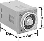
Solid State Versa-Mount Timer Relays
Mount these timer relays in a panel cutout or plug them into a relay socket for quick installation. Capable of fast switching, they are solid state and have no moving parts, so they require less maintenance, last longer, and are quieter than mechanical relays. Unlike standard relays that switch on and off immediately, timer relays delay before the circuit stops or starts.
Relays with an asymmetrical repeat cycle begin in an on state, then alternate between different durations of off and on for as long as input voltage is applied. For example, a heating system starts with an on period, then switches to an off period once the desired temperature is reached.
Relays with a start-off asymmetrical repeat cycle begin in an off state, then alternate between different durations of on and off for as long as input voltage is applied. For example, an irrigation system receives a signal and starts in the off state, allowing water to fill before switching on to start pumping.
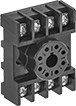
Relay sockets (sold separately) mount to 35 mm DIN rail (also known as DIN 3 rail) or can be mounted to a flat surface.
Mounting brackets (sold separately) are required to mount the relay into a panel.
Timer Relays | ||||||||||||
|---|---|---|---|---|---|---|---|---|---|---|---|---|
Timing Range | Relay Sockets | |||||||||||
| Number of Terminals | Input Voltage | Control Current, mA | No. of | Overall | Switching Current @ 240V AC | Ht. | Wd. | Dp. | Each | Each | ||
Asymmetrical Repeat Cycle | ||||||||||||
2 Circuits Controlled with 2 Off (Normally Open) or 2 On (Normally Closed)—DPDT | ||||||||||||
| 8 | 120V AC, 240V AC, 110V DC, 120V DC | 41 | 4 | 0.05 sec.-300 hrs. | 5A | 1.9" | 1.9" | 3.3" | 000000000 | 0000000 | 0000000 | 00000 |
| 11 | 120V AC, 240V AC, 110V DC, 120V DC | 41 | 4 | 0.05 sec.-300 hrs. | 5A | 1.9" | 1.9" | 3.3" | 0000000 | 000000 | 0000000 | 00000 |
Start-Off Asymmetrical Repeat Cycle | ||||||||||||
2 Circuits Controlled with 2 Off (Normally Open) or 2 On (Normally Closed)—DPDT | ||||||||||||
| 8 | 120V AC, 240V AC, 110V DC, 120V DC | 41 | 4 | 0.05 sec.-300 hrs. | 5A | 1.9" | 1.9" | 3.3" | 000000000 | 000000 | 0000000 | 0000 |
| 11 | 120V AC, 240V AC, 110V DC, 120V DC | 41 | 4 | 0.05 sec.-300 hrs. | 5A | 1.9" | 1.9" | 3.3" | 00000000 | 000000 | 0000000 | 00000 |
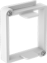
Mounting Hole | ||||||||||
|---|---|---|---|---|---|---|---|---|---|---|
| Material | Mounting Location | No. of | Ctr.-to-Ctr. | Dia. | Mounting Fasteners Included | Screw Size | Ht. | Wd. | Each | |
| Polycarbonate | Panel | 2 | 3" | 5mm | Yes | M5 | 2.28" | 1.89" | 0000000 | 000000 |