


Compact Spade-Terminal Relays
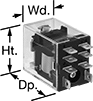
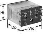

Fit these relays where standard spade-terminal relays are too big. You can connect them three ways. Plug them into a socket (sold separately), connect them with quick-disconnect terminals, or solder wires directly to the terminals. An LED indicator shows you the status of the relay, so you know it’s connected and wired correctly.
Relays that control 2 or more circuits have a lockable test button, so you can test their function. When you press the button, the relay switches contacts. Use this button when checking a relay for proper function before installing it, or when investigating issues with wired relays.
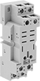
Relay sockets mount directly on 35 mm DIN rail (also known as DIN 3 rail) for fast installation. You can also mount them to a flat surface using screws.
Relays | Relay Sockets with Screw Terminals | |||||||||||
|---|---|---|---|---|---|---|---|---|---|---|---|---|
| Number of Terminals | Input Voltage | Control Current, mA | Switching Current @ Voltage | Maximum Switching Voltage | Ht. | Wd. | Dp. | Quick-Disconnect Tab Wd. | Each | Each | ||
2 Circuits Controlled with 2 Off (Normally Open) or 2 On (Normally Closed)—DPDT | ||||||||||||
Relay-Socket Mount | ||||||||||||
| 8 | 24V AC | 50 | 10 A @ 120 V AC/24 V DC | 300V AC | 1.1" | 0.8" | 1.6" | 0.11" | 69585K111 | 000000 | 69585K6 | 00000 |
| 8 | 24V AC | 50 | 15 A @ 120 V AC 12 A @ 24 V DC | 300V AC | 1.1" | 0.9" | 1.6" | 0.187" | 69585K57 | 00000 | 69585K1 | 0000 |
4 Circuits Controlled with 4 Off (Normally Open) or 4 On (Normally Closed)—4PDT | ||||||||||||
Relay-Socket Mount | ||||||||||||
| 14 | 24V AC | 50 | 8 A @ 120 V AC/24 V DC | 300V AC | 1.1" | 0.9" | 1.6" | 0.11" | 69585K121 | 00000 | 69585K6 | 0000 |
Latching Relays
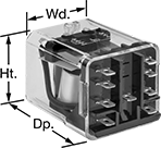
A single, momentary input voltage switches these relays and latches them in position, so they don't require a constant input voltage to stay switched. A second momentary voltage will release the latch.
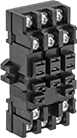
Relay sockets (sold separately) mount to 35 mm DIN rail (also known as DIN 3 rail) for fast installation.
Relays | Relay Sockets | |||||||||||
|---|---|---|---|---|---|---|---|---|---|---|---|---|
| Number of Terminals | Input Voltage | Control Current, mA | Switching Current @ 240V AC/24V DC | hp @ Switching Voltage | Ht. | Wd. | Dp. | Quick-Disconnect Tab Wd. | Each | Each | ||
2 Circuits Controlled with 2 Off (Normally Open) or 2 On (Normally Closed)—DPDT | ||||||||||||
| 9 | 24V DC | 50 | 10A | 1/3 hp @ 120 V AC 1/2 hp @ 240 V AC | 1.4" | 1.5" | 1.9" | 0.187" | 1358T14 | 000000 | 1358T21 | 000000 |
Analog-Input Proportional-Control Relays
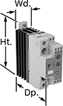
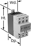
Often used to regulate the speed of AC fans or keep a heater at a set temperature, these relays connect directly to sensors to calculate and adjust output power. This allows you to use an analog input without converting it to a digital signal to control output power. They are solid state and have no moving parts, so they require less maintenance and last longer, are quieter, and switch faster than mechanical relays. IP20 rated, they have recessed terminals that prevent fingers and other objects from touching live circuits. An integrated heat sink disperses heat to increase the relay’s current rating. The LED indicator shows input voltage loss and internal relay faults, so you can easily check that your system is operating properly.
Mount them on 35 mm DIN rail (also known as DIN 3 rail) for fast installation. They also mount to flat surfaces.
All relays have phase-angle switching to accurately control all types of loads. This mode signals at non-zero voltage, which can produce electrical noise. Choose relays with full-cycle switching for resistive loads. This mode signals at zero voltage, so electrical interference is lower than phase-angle switching.
Single-phase relays can be set to switch every 1, 4, or 16 cycles. When used with infrared heaters, they have an option to switch at the half cycle and again at the full cycle. When switching at 16 cycles or at the half cycle, these relays have a soft-start option to increase the output slower in high-inrush current applications.
Three-phase relays switch every cycle.
Relays with a potentiometer input can connect to an external potentiometer for manual control.
Relays with over-temperature protection stop power when it gets too hot and keeps it off until the issue is resolved. Connect an auxiliary contact (not included) to signal an alarm or status controller.
Relays with short-circuit protection stop power if there is an open circuit, short circuit, or output voltage loss until the issue is resolved. Connect an auxiliary contact (not included) to signal an alarm or status controller.
Input | Output | |||||||||||||||
|---|---|---|---|---|---|---|---|---|---|---|---|---|---|---|---|---|
| Number of Terminals | Voltage | Current | No. of | Voltage | Current | No. of | Control Current, mA | Switching Current @ Voltage | Max. Switching Voltage | Protections Provided | Ht. | Wd. | Dp. | Features | Each | |
1 Circuit Controlled with 1 Off (Normally Open)—SPST-NO | ||||||||||||||||
Single Phase with Phase Angle Switching Mode | ||||||||||||||||
| 4 | __ | 4-20mA | 1 | 85-265V AC | 30A | 1 | 50 | 30 A @ 230 V AC | 265V AC | __ | 4.33" | 1.4" | 4.08" | Integrated Heat Sink, LED Indicator, Recessed Terminals | 7048N11 | 0000000 |
| 4 | __ | 4-20mA | 1 | 85-265V AC | 42A | 1 | 50 | 42 A @ 230 V AC | 265V AC | __ | 4.33" | 1.4" | 4.08" | Integrated Heat Sink, LED Indicator, Recessed Terminals | 7048N13 | 000000 |
| 4 | __ | 4-20mA | 1 | 190-550V AC | 30A | 1 | 50 | 30 A @ 480 V AC | 550V AC | __ | 4.33" | 1.4" | 4.08" | Integrated Heat Sink, LED Indicator, Recessed Terminals | 7048N12 | 000000 |
| 4 | __ | 4-20mA | 1 | 190-550V AC | 42A | 1 | 50 | 42 A @ 480 V AC | 550V AC | __ | 4.33" | 1.4" | 4.08" | Integrated Heat Sink, LED Indicator, Recessed Terminals | 7048N14 | 000000 |
| 9 | 0-10V DC | __ | 1 | 85-265V AC | 30A | 1 | 50 | 30 A @ 230 V AC | 265V AC | __ | 4.33" | 1.4" | 4.08" | Integrated Heat Sink, LED Indicator, Recessed Terminals, Potentiometer Input | 7048N15 | 000000 |
| 9 | 0-10V DC | __ | 1 | 85-265V AC | 42A | 1 | 50 | 42 A @ 230 V AC | 265V AC | __ | 4.33" | 1.4" | 4.08" | Integrated Heat Sink, LED Indicator, Recessed Terminals, Potentiometer Input | 7048N16 | 000000 |
| 9 | 0-10V DC | __ | 1 | 190-550V AC | 30A | 1 | 50 | 30 A @ 480 V AC | 550V AC | __ | 4.33" | 1.4" | 4.08" | Integrated Heat Sink, LED Indicator, Recessed Terminals, Potentiometer Input | 7048N17 | 000000 |
| 9 | 0-10V DC | __ | 1 | 190-550V AC | 42A | 1 | 50 | 42 A @ 480 V AC | 550V AC | __ | 4.33" | 1.4" | 4.08" | Integrated Heat Sink, LED Indicator, Recessed Terminals, Potentiometer Input | 7048N18 | 000000 |
3 Circuits Controlled with 3 Off (Normally Open)—3PST-NO | ||||||||||||||||
Three Phase with Phase Angle and Full Cycle Switching Mode | ||||||||||||||||
| 8 | __ | 4-20mA | 1 | 180-660V AC | 20A | 3 | 50 | 20 A @ 600 V AC | 660V AC | __ | 4.3" | 2.1" | 4" | Integrated Heat Sink, LED Indicator, Recessed Terminals | 7048N19 | 000000 |
| 8 | __ | 4-20mA | 1 | 180-660V AC | 30A | 3 | 50 | 30 A @ 600 V AC | 660V AC | __ | 4.3" | 2.84" | 4.95" | Integrated Heat Sink, LED Indicator, Recessed Terminals | 7048N21 | 000000 |
| 19 | __ | 0-20mA | 1 | 180-660V AC | 65A | 3 | 50 | 65 A @ 600 V AC | 660V AC | Over Temperature | 4.3" | 2.84" | 5.56" | Integrated Heat Sink, LED Indicator, Recessed Terminals, Integrated Fan | 7048N23 | 000000 |
| 19 | __ | 0-20mA | 1 | 180-660V AC | 65A | 3 | 50 | 65 A @ 600 V AC | 660V AC | Short Circuit | 4.3" | 2.84" | 5.56" | Integrated Heat Sink, LED Indicator, Recessed Terminals, Integrated Fan, Open Circuit, Configurable Alarm Outputs, Output Voltage Loss | 7048N22 | 000000 |