


Compact Spade-Terminal Relays
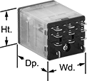
Fit these relays where standard spade-terminal relays are too big. You can connect them three ways. Plug them into a socket (sold separately), connect them with quick-disconnect terminals, or solder wires directly to the terminals. An LED indicator shows you the status of the relay, so you know it’s connected and wired correctly.
Relays that control 2 or more circuits have a lockable test button, so you can test their function. When you press the button, the relay switches contacts. Use this button when checking a relay for proper function before installing it, or when investigating issues with wired relays.
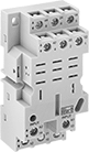
Relay sockets mount directly on 35 mm DIN rail (also known as DIN 3 rail) for fast installation. You can also mount them to a flat surface using screws.
![]() For technical drawings and 3-D models, click on a part number.
For technical drawings and 3-D models, click on a part number.
Relays | Relay Sockets with Screw Terminals | |||||||||||
|---|---|---|---|---|---|---|---|---|---|---|---|---|
| Number of Terminals | Input Voltage | Control Current, mA | Switching Current @ Voltage | Maximum Switching Voltage | Ht. | Wd. | Dp. | Quick-Disconnect Tab Wd. | Each | Each | ||
3 Circuits Controlled with 3 Off (Normally Open) or 3 On (Normally Closed)—3PDT | ||||||||||||
Relay-Socket Mount | ||||||||||||
| 11 | 24V DC | 58 | 15 A @ 120 V AC 12 A @ 24 V DC | 300V AC | 1.1" | 1.2" | 1.6" | 0.187" | 00000000 | 000000 | 0000000 | 000000 |
Circuit Board Safety Relays
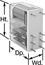
Reduce connection errors on circuit boards that control machine guards and other safety devices. Also known as force-guided contact relays, they have contact pairs that won’t close at the same time, even if contacts stick or weld shut. These relays take up less space on a board than those with electrical wiring because their solder pin terminals mount directly through circuit board holes. Use them to control high-power components, such as fans and heaters, from a low-power circuit.
Relays with a mechanical indicator show you whether they’re switched on or off with a flag. Peek through the window on the side to quickly check the flag’s position.
![]() For technical drawings and 3-D models, click on a part number.
For technical drawings and 3-D models, click on a part number.
| Number of Terminals | Input Voltage | Control Current, mA | Switching Current @ Voltage | Max. Switching Voltage | Mechanical Life Cycles | Ht. | Wd. | Dp. | Pin Lg. | Features | Each | |
2 Circuits Controlled with 2 Off (Normally Open) or 2 On (Normally Closed)—DPDT | ||||||||||||
|---|---|---|---|---|---|---|---|---|---|---|---|---|
| 8 | 12V DC | 58 | 3 A @ 240 V AC/24 V DC | 250V AC, 125V DC | 10,000,000 | 1.1" | 0.5" | 1" | 0.16" | Interlocked Opposing Contacts, Mechanical Indicator | 0000000 | 000000 |