


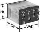
Compact Spade-Terminal Relays
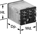

Fit these relays where standard spade-terminal relays are too big. You can connect them three ways. Plug them into a socket (sold separately), connect them with quick-disconnect terminals, or solder wires directly to the terminals. An LED indicator shows you the status of the relay, so you know it’s connected and wired correctly.
Relays that control 2 or more circuits have a lockable test button, so you can test their function. When you press the button, the relay switches contacts. Use this button when checking a relay for proper function before installing it, or when investigating issues with wired relays.
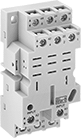
Relay sockets mount directly on 35 mm DIN rail (also known as DIN 3 rail) for fast installation. You can also mount them to a flat surface using screws.
Relays | Relay Sockets with Screw Terminals | |||||||||||
|---|---|---|---|---|---|---|---|---|---|---|---|---|
| Number of Terminals | Input Voltage | Control Current, mA | Switching Current @ Voltage | Maximum Switching Voltage | Ht. | Wd. | Dp. | Quick-Disconnect Tab Wd. | Each | Each | ||
3 Circuits Controlled with 3 Off (Normally Open) or 3 On (Normally Closed)—3PDT | ||||||||||||
Relay-Socket Mount | ||||||||||||
| 11 | 24V AC | 63 | 15 A @ 120 V AC 12 A @ 24 V DC | 300V AC | 1.1" | 1.2" | 1.6" | 0.187" | 00000000 | 000000 | 0000000 | 000000 |
4 Circuits Controlled with 4 Off (Normally Open) or 4 On (Normally Closed)—4PDT | ||||||||||||
Relay-Socket Mount | ||||||||||||
| 14 | 24V AC | 63 | 15 A @ 120 V AC 12 A @ 24 V DC | 300V AC | 1.1" | 1.6" | 1.6" | 0.187" | 00000000 | 00000 | 0000000 | 00000 |
Interface Safety Relays
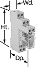
These relays pair the transmission reliability of an interface relay with the fail-safe operation of a safety relay. Use them to communicate signals to devices like motors or sensors. They have interlocking contacts—also known as force-guided or mechanically linked contacts—so opposing contacts won't close at the same time. This minimizes the chance of arcing, so electricity won't jump across the contacts and interfere with your relay or system. They also have an interface that isolates input and output circuits to prevent damage from voltage spikes, reduce signal interference, and amplify signal. Mount them on 35 mm DIN rail (also known as DIN 3 rail). The relays disconnect from the socket for quick replacement.
Relays with LED indicator light up when the relay is on, so you’ll know it’s wired correctly and can tell at a glance whether it’s on or off.
Relays | Replacement Relays | ||||||||||||
|---|---|---|---|---|---|---|---|---|---|---|---|---|---|
| Number of Terminals | Input Voltage | Control Current, mA | Switching Current @ Voltage | Max. Switching Voltage | Mechanical Life Cycles | Ht. | Wd. | Dp. | Features | Each | Each | ||
2 Circuits Controlled with 1 Off (Normally Open) and 1 On (Normally Closed)—DPST-1NO/1NC | |||||||||||||
| 6 | 12V DC | 63 | 3 A @ 240 V AC/24 V DC | 250V AC, 125V DC | 10,000,000 | 1.1" | 0.5" | 1.1" | Interlocked Opposing Contacts, LED Indicator | 0000000 | 000000 | 0000000 | 000000 |