


Filter by
System of Measurement
Timer Function
Mounting Location
Overall Timing
Operation Type
Switch Starting Position
Certification
Wire Connection
Control Current


Electrical Connection
U.S.–Mexico–Canada Agreement (USMCA) Qualifying
DFARS Specialty Metals
Export Control Classification Number (ECCN)
About Timer Relays
Use our timing charts to compare common timer functions. Plus, learn how applying or removing input voltage triggers relays.
DIN-Rail Mount Multifunction Timer Relays
Timer Relays with Delayed, Interval, Switch On, and Repeat Cycles
 |
1 Circuit Controlled |
 |
2 Circuits Controlled |
Timer relays with delayed, interval, switch-on, and repeat cycles have a broad range of applications. Use them to precisely control machines such as conveyors, lighting systems, and electric motors.
Delayed Start (Delay on Make) Timer—This function allows you to set how long it takes for the relay to turn on after input voltage is applied. For example, a drill starts pumping lubricant immediately, but it does not start rotating until the set time has elapsed.
Delayed Switch Off (Delay on Break) Timer—This function uses a switch instead of input voltage. When the switch is turned off, the relay remains on for a programmed amount of time before turning off. For example, a projector’s light is turned off with a switch, but its cooling fan continues to run for a set time.
Delayed Switch-On with Delayed Switch-Off Timer—This function uses a switch instead of input voltage. It allows you to set how long the relay takes to turn on after a switch is turned on, and how long it will stay on after the switch is turned off. For example, a furnace turns on, but the fan doesn’t start pushing air through the vents until it has been heated. When the furnace turns off, the fan keeps blowing to circulate all the hot air.
Delayed-Pulse Timer—This function uses input voltage to turn on the relay for a brief period after a preset time. For example, a light flashes a few seconds after a door closes.
Interval Timer—This function uses input voltage to turn on the relay for a programmed amount of time. For example, when a part moving down a conveyor reaches a certain location, a cleaning spray comes on for a set time.
Interval Switch-Off Timer—This function requires a switch to activate the relay, which stays off for the programmed amount of time. For example, lights in a storage room are turned on with a switch and stay on for a set time before turning off.
Switch on (Single Shot) Timer—This function requires a switch to activate the relay, which stays on for the programmed amount of time. For example, lights in a storage room are turned on with a switch and stay on for a set time before turning off.
Repeat-Cycle Timer—This function starts with an on cycle and then alternates between an on cycle and off cycle of equal durations until input voltage is removed. A common example would be a flashing light.
Start-Off Repeat Cycle Timer—This function starts with an off cycle and alternates between an on cycle and off cycle of equal durations until input voltage is removed. A common example would be a flashing light.
Switch Fixed On/Off Timer—This function requires a switch to activate the timing function instead of the input voltage (which is applied the entire time). It keeps the relay on whenever the switch is closed; it will only turn off if the switch is open.
Timing Range | ||||||||||||||
|---|---|---|---|---|---|---|---|---|---|---|---|---|---|---|
No. of Terminals | Input Voltage | Control Current, mA | Timer Relay Function | No. of | Overall | Switching Current @ Voltage | Max. Switching Voltage, V AC | Ht. | Wd. | Dp. | Each | |||
1 Circuit Controlled with 1 Off or 1 On—SPDT | ||||||||||||||
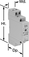
| 6 | 12V AC, 24V AC, 48V AC, 120V AC, 240V AC, 12V DC, 24V DC, 48V DC, 60V DC, 120V DC, 240V DC | 7 | Delayed Start (Delay on Make) Delayed Switch Off (Delay on Break) Delayed Switch-On with Delayed Switch-Off Interval Switch on (Single Shot) Repeat Cycle | 6 | 0.1 sec. to 24 hr. | 16 amp @ 240V AC | 250 | 3.5" | 0.7" | 2.4" | 6964K4 | 000000 | ||
2 Circuits Controlled with 2 Off or 2 On—DPDT | ||||||||||||||
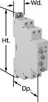
| 8 | 12V AC, 24V AC, 48V AC, 120V AC, 240V AC, 12V DC, 24V DC, 48V DC, 60V DC, 120V DC, 240V DC | 7 | Delayed Start (Delay on Make) Delayed Switch Off (Delay on Break) Delayed Switch-On with Delayed Switch-Off Delayed Pulse Interval Interval Switch-Off Switch on (Single Shot) Repeat Cycle Start-Off Repeat Cycle Switch Fixed On/Off | 8 | 0.1 sec. to 10 day | 8 amp @ 240V AC | 250 | 4.1" | 0.7" | 2.6" | 6964K103 | 000000 | ||
Timer Relays with Asymmetrical Repeat Cycles
|
1 Circuit Controlled |
Use timer relays with asymmetrical repeat cycles when your repeat cycles have different on- and off-cycle durations.
Asymmetrical-Repeat-Cycle Timer—This function switches the relay on and alternates between different durations of on and off for as long as input voltage is applied. For example, a sprinkler system sprays in short bursts followed by longer rest periods, on and off until input voltage is removed.
Switch-On Asymmetrical Repeat Cycle Timer—This function switches the relay on and alternates between different durations of on and off for as long as input voltage is applied. It requires a switch to activate the timing function instead of the input voltage that’s being applied the entire time. You could use this function to turn on an electric motor for a short period and then turn it off for a longer rest period, repeating that pattern until the switch is turned off.
Timing Range | ||||||||||||||
|---|---|---|---|---|---|---|---|---|---|---|---|---|---|---|
No. of Terminals | Input Voltage | Control Current, mA | Timer Relay Function | No. of | Overall | Switching Current @ Voltage | Max. Switching Voltage, V AC | Ht. | Wd. | Dp. | Each | |||
1 Circuit Controlled with 1 Off or 1 On—SPDT | ||||||||||||||
| 6 | 12V AC, 24V AC, 48V AC, 120V AC, 240V AC, 12V DC, 24V DC, 48V DC, 60V DC, 120V DC, 240V DC | 7 | Asymmetrical Repeat Cycle Switch-On Asymmetrical Repeat Cycle | 6 | 0.1 sec. to 24 hr. | 16 amp @ 240V AC | 250 | 3.5" | 0.7" | 2.4" | 6964K17 | 000000 | ||
Circuit Board Relays
 |
4 Terminals |
Smaller than relays with electrical wiring, these relays fit in compact devices. Mount them through holes on circuit boards with their solder pin terminals. Use them to control heaters, fans, and other high-power components from a low-power circuit.
Solid-State Operation—Solid state relays have no moving parts, so they require less maintenance and last longer, switch faster, and are quieter than mechanical relays.
No. of Terminals | Input Voltage | Control Current, mA | Switching Current @ Voltage | Max. Switching Voltage | Ht. | Wd. | Dp. | Pin Lg. | Each | |||
|---|---|---|---|---|---|---|---|---|---|---|---|---|
Solid-State Operation | ||||||||||||
1 Circuit Controlled with 1 Off—SPST-NO | ||||||||||||
| 4 | 24V DC | 7 | 2 amp @ 240V AC | 250V AC | 1.1" | 0.2" | 0.6" | 0.14" | 4799T22 | 000000 | ||
| 4 | 24V DC | 7 | 6 amp @ 24V DC | 24V DC | 1.1" | 0.2" | 0.6" | 0.14" | 4799T23 | 00000 | ||
| 4 | 60V DC | 7 | 6 amp @ 24V DC | 24V DC | 1.1" | 0.2" | 0.6" | 0.14" | 8262T18 | 00000 | ||
Solid State DIN-Rail Mount Timer Relays
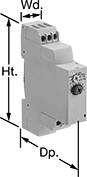 |
Mount these timer relays directly to 35 mm DIN rail (also known as DIN 3 rail) for fast installation. Unlike mechanical relays, they have no moving parts, so they require less maintenance and last longer, are quieter, and switch faster. After selecting a timing range, use the knob to adjust the trip time within the timing range.
Timing Range | |||||||||||||
|---|---|---|---|---|---|---|---|---|---|---|---|---|---|
No. of Terminals | Input Voltage | Control Current, mA | No. of | Overall | Switching Current @ Voltage | Max. Switching Voltage, V AC | Ht. | Wd. | Dp. | Each | |||
Delayed Start (Delay on Make) | |||||||||||||
1 Circuit Controlled with 1 Off—SPST-NO | |||||||||||||
| 6 | 24V AC, 48V AC, 120V AC, 240V AC, 24V DC, 48V DC, 60V DC, 120V DC, 240V DC | 7 | 7 | 0.1 sec. to 100 hr. | 0.7 amp @ 240V AC | 250 | 3 1/2" | 0.7" | 2.7" | 7801K51 | 000000 | ||
Interval | |||||||||||||
1 Circuit Controlled with 1 Off—SPST-NO | |||||||||||||
| 6 | 24V AC, 48V AC, 120V AC, 240V AC | 7 | 7 | 0.1 sec. to 100 hr. | 0.7 amp @ 240V AC | 250 | 3 1/2" | 0.7" | 2.7" | 7801K52 | 00000 | ||
Spade-Terminal Relays
Surface Mount
 |
5 Terminals |
Surface mount relays, also known as power relays, have a slot on the flange for mounting them to flat surfaces.
No. of Terminals | Input Voltage, V AC | Control Current, mA | Max. Switching Voltage, V AC | hp @ Switching Voltage | Ht. | Wd. | Dp. | Quick-Disconnect Tab Wd. | Each | |||
|---|---|---|---|---|---|---|---|---|---|---|---|---|
1 Circuit Controlled with 1 Off or 1 On—SPDT | ||||||||||||
| 5 | 120 | 7 | 380 | 1/3 hp @ 120V AC | 0.6" | 1.8" | 1.16" | 0.187" | 7098K52 | 000000 | ||
