


Filter by
Switching Voltage

Mounting Location
Switch Action
Switch Starting Position
Operation Type
Electrical Connection


Relay Type

Socket Connection


Mechanical Life Cycles
Wire Connection
Certification
DFARS Specialty Metals
Export Control Classification Number (ECCN)
Sequenced Latching Relays
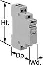 |
These relays switch through a series of different circuit configurations every time they receive an input voltage. The input voltage latches them in position, so they don’t require a constant voltage to stay switched. Use them to control motors, pumps, and lighting. The covered terminals prevent contact with live connections. Mount to 35 mm DIN rail. Also known as step relays.
Switch Starting Position | Input Voltage | Control Power | Switching Current @ Voltage | Max. Switching Voltage, V AC | hp @ Switching Voltage | Ht. | Wd. | Dp. | Each | |||
|---|---|---|---|---|---|---|---|---|---|---|---|---|
1 Circuit Controlled—SPST-NO | ||||||||||||
4 Terminals | ||||||||||||
| 1st Signal—1 Off 2nd Signal—1 On | 24V AC | 6.5 VA | 16 amp @ 120V AC | 277 | 1/2 hp @ 120V AC | 3.3" | 0.7" | 2.4" | 6784T111 | 000000 | ||
| 1st Signal—1 Off 2nd Signal—1 On | 120V AC | 6.5 VA | 16 amp @ 120V AC | 277 | 1/2 hp @ 120V AC | 3.3" | 0.7" | 2.4" | 6784T112 | 00000 | ||
| 1st Signal—1 Off 2nd Signal—1 On | 240V AC | 6.5 VA | 16 amp @ 120V AC | 277 | 1/2 hp @ 120V AC | 3.3" | 0.7" | 2.4" | 6784T113 | 00000 | ||
| 1st Signal—1 Off 2nd Signal—1 On | 12V DC | 5 W | 16 amp @ 120V AC | 277 | 1/2 hp @ 120V AC | 3.3" | 0.7" | 2.4" | 6784T114 | 00000 | ||
| 1st Signal—1 Off 2nd Signal—1 On | 24V DC | 5 W | 16 amp @ 120V AC | 277 | 1/2 hp @ 120V AC | 3.3" | 0.7" | 2.4" | 6784T115 | 00000 | ||
2 Circuits Controlled—DPST-1NO/1NC | ||||||||||||
6 Terminals | ||||||||||||
| 1st Signal—1 Off and 1 On 2nd Signal—1 Off and 1 On | 24V AC | 6.5 VA | 16 amp @ 120V AC | 277 | 1/2 hp @ 120V AC | 3.3" | 0.7" | 2.4" | 6784T131 | 00000 | ||
| 1st Signal—1 Off and 1 On 2nd Signal—1 Off and 1 On | 120V AC | 6.5 VA | 16 amp @ 120V AC | 277 | 1/2 hp @ 120V AC | 3.3" | 0.7" | 2.4" | 6784T132 | 00000 | ||
| 1st Signal—1 Off and 1 On 2nd Signal—1 Off and 1 On | 240V AC | 6.5 VA | 16 amp @ 120V AC | 277 | 1/2 hp @ 120V AC | 3.3" | 0.7" | 2.4" | 6784T133 | 00000 | ||
| 1st Signal—1 Off and 1 On 2nd Signal—1 Off and 1 On | 12V DC | 5 W | 16 amp @ 120V AC | 277 | 1/2 hp @ 120V AC | 3.3" | 0.7" | 2.4" | 6784T134 | 00000 | ||
| 1st Signal—1 Off and 1 On 2nd Signal—1 Off and 1 On | 24V DC | 5 W | 16 amp @ 120V AC | 277 | 1/2 hp @ 120V AC | 3.3" | 0.7" | 2.4" | 6784T135 | 00000 | ||
2 Circuits Controlled—DPST-NO | ||||||||||||
6 Terminals | ||||||||||||
| 1st Signal—2 Off 2nd Signal—1 Off and 1 On 3rd Signal—2 On | 24V AC | 6.5 VA | 16 amp @ 120V AC | 277 | 1/2 hp @ 120V AC | 3.3" | 0.7" | 2.4" | 6784T141 | 00000 | ||
| 1st Signal—2 Off 2nd Signal—1 Off and 1 On 3rd Signal—2 On | 120V AC | 6.5 VA | 16 amp @ 120V AC | 277 | 1/2 hp @ 120V AC | 3.3" | 0.7" | 2.4" | 6784T142 | 00000 | ||
| 1st Signal—2 Off 2nd Signal—1 Off and 1 On 3rd Signal—2 On | 240V AC | 6.5 VA | 16 amp @ 120V AC | 277 | 1/2 hp @ 120V AC | 3.3" | 0.7" | 2.4" | 6784T143 | 00000 | ||
| 1st Signal—2 Off 2nd Signal—1 Off and 1 On 3rd Signal—2 On | 12V DC | 5 W | 16 amp @ 120V AC | 277 | 1/2 hp @ 120V AC | 3.3" | 0.7" | 2.4" | 6784T144 | 00000 | ||
| 1st Signal—2 Off 2nd Signal—1 Off and 1 On 3rd Signal—2 On | 24V DC | 5 W | 16 amp @ 120V AC | 277 | 1/2 hp @ 120V AC | 3.3" | 0.7" | 2.4" | 6784T145 | 00000 | ||
| 1st Signal—2 Off 2nd Signal—2 On | 24V AC | 6.5 VA | 16 amp @ 120V AC | 277 | 1/2 hp @ 120V AC | 3.3" | 0.7" | 2.4" | 6784T121 | 00000 | ||
| 1st Signal—2 Off 2nd Signal—2 On | 120V AC | 6.5 VA | 16 amp @ 120V AC | 277 | 1/2 hp @ 120V AC | 3.3" | 0.7" | 2.4" | 6784T122 | 00000 | ||
| 1st Signal—2 Off 2nd Signal—2 On | 240V AC | 6.5 VA | 16 amp @ 120V AC | 277 | 1/2 hp @ 120V AC | 3.3" | 0.7" | 2.4" | 6784T123 | 00000 | ||
| 1st Signal—2 Off 2nd Signal—2 On | 12V DC | 5 W | 16 amp @ 120V AC | 277 | 1/2 hp @ 120V AC | 3.3" | 0.7" | 2.4" | 6784T124 | 00000 | ||
| 1st Signal—2 Off 2nd Signal—2 On | 24V DC | 5 W | 16 amp @ 120V AC | 277 | 1/2 hp @ 120V AC | 3.3" | 0.7" | 2.4" | 6784T125 | 00000 | ||
Latching Relays
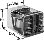 | 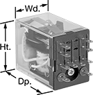 | 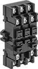 | 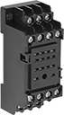 |
9 Terminals | 10 Terminals | 9-Terminal Relay Socket | 10-Terminal Relay Socket |
Relays | Relay Sockets | |||||||||||||
|---|---|---|---|---|---|---|---|---|---|---|---|---|---|---|
No. of Terminals | Input Voltage | Control Current, mA | Switching Current @ Voltage | hp @ Switching Voltage | Ht. | Wd. | Dp. | Quick-Disconnect Tab Wd. | Each | Each | ||||
2 Circuits Controlled with 2 Off or 2 On—DPDT | ||||||||||||||
| 9 | 24V AC | 70 | 10 amp @ 240V AC/24V DC | 1/3 hp @ 120V AC 1/2 hp @ 240V AC | 1.4" | 1.5" | 1.9" | 0.187" | 1358T11 | 000000 | 1358T21 | 000000 | ||
| 9 | 120V AC | 14 | 10 amp @ 240V AC/24V DC | 1/3 hp @ 120V AC 1/2 hp @ 240V AC | 1.4" | 1.5" | 1.9" | 0.187" | 1358T12 | 00000 | 1358T21 | 00000 | ||
| 9 | 12V DC | 100 | 10 amp @ 240V AC/24V DC | 1/3 hp @ 120V AC 1/2 hp @ 240V AC | 1.4" | 1.5" | 1.9" | 0.187" | 1358T13 | 00000 | 1358T21 | 00000 | ||
| 9 | 24V DC | 50 | 10 amp @ 240V AC/24V DC | 1/3 hp @ 120V AC 1/2 hp @ 240V AC | 1.4" | 1.5" | 1.9" | 0.187" | 1358T14 | 00000 | 1358T21 | 00000 | ||
| 10 | 24V AC | 27 | 3 amp @ 240V AC/24V DC | — | 1.1" | 0.8" | 1.4" | 0.102" | 1358T32 | 000000 | 1358T93 | 00000 | ||
| 10 | 12V DC | 110 | 3 amp @ 240V AC/24V DC | — | 1.1" | 0.8" | 1.4" | 0.102" | 1358T31 | 00000 | 1358T93 | 00000 | ||
| 10 | 24V DC | 52 | 3 amp @ 240V AC/24V DC | — | 1.1" | 0.8" | 1.4" | 0.102" | 1358T33 | 00000 | 1358T93 | 00000 | ||
High-Current Lighting Relays
Mechanically Held
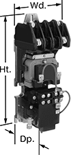 | 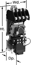 | 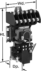 |
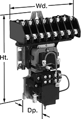
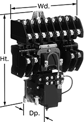
2 Circuits Controlled | 4 Circuits Controlled | 6 Circuits Controlled |
 |  | |
8 Circuits Controlled | 12 Circuits Controlled |
No. of Terminals | Input Voltage, V AC | Control Power, VA | Switching Current @ Voltage (Light Technology) | Max. Switching Voltage, V AC | Mechanical Life Cycles | Ht. | Wd. | Dp. | Each | |||
|---|---|---|---|---|---|---|---|---|---|---|---|---|
2 Circuits Controlled with 2 Off—DPST-NO | ||||||||||||
| 6 | 120 | 30 | 30 amp @ 120V AC (Fluorescent) 20 amp @ 120V AC (Incandescent) | 132 | 1,000,000 | 8.8" | 2.9" | 3.3" | 8466N21 | 0000000 | ||
4 Circuits Controlled with 4 Off—4PST-NO | ||||||||||||
| 10 | 120 | 30 | 30 amp @ 120V AC (Fluorescent) 20 amp @ 120V AC (Incandescent) | 132 | 1,000,000 | 8.8" | 2.9" | 3.3" | 8466N22 | 000000 | ||
6 Circuits Controlled with 6 Off—6PST-NO | ||||||||||||
| 14 | 120 | 30 | 30 amp @ 120V AC (Fluorescent) 20 amp @ 120V AC (Incandescent) | 132 | 1,000,000 | 8.8" | 4.3" | 3.3" | 8466N23 | 000000 | ||
8 Circuits Controlled with 8 Off—8PST-NO | ||||||||||||
| 18 | 120 | 35 | 30 amp @ 120V AC (Fluorescent) 20 amp @ 120V AC (Incandescent) | 132 | 1,000,000 | 8.8" | 5.6" | 3.3" | 8466N24 | 00000000 | ||
12 Circuits Controlled with 12 Off—12PST-NO | ||||||||||||
| 26 | 120 | 35 | 30 amp @ 120V AC (Fluorescent) 20 amp @ 120V AC (Incandescent) | 132 | 1,000,000 | 8.8" | 5.6" | 3.3" | 8466N19 | 00000000 | ||
Current-Monitoring Relays
 |
Screw Terminals Knob Adjustment |
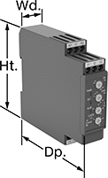
Protect electrical equipment from overcurrent and undercurrent damage—these relays continuously monitor current flow. When current is outside a set range, they trip and cut power to prevent overheating, fire hazards, and stalling. Rated IP20, these relays have recessed terminals that keep fingers and other objects from touching live circuits. Mount them on a 35 mm DIN rail (also known as DIN 3 rail) for fast installation.
Knob Adjustment—Relays with knob adjustments have knobs right on the front where you can set your trip current. You can see that they're wired correctly and when they're actuated based on the LED indicators.
No. of Terminals | Input Voltage | Trip Current Setting, amp | Trip Time, sec. | Reset Type | Switching Current @ Voltage | Max. Switching Voltage | Adjustment Mechanism | Ht. | Wd. | Dp. | Each | |||
|---|---|---|---|---|---|---|---|---|---|---|---|---|---|---|
Screw Terminals | ||||||||||||||
1 Circuit Controlled with 1 Off or 1 On—SPDT | ||||||||||||||
| 9 | 24V AC, 24V DC | 0.1 to 1, 0.5 to 5, 0.8 to 8 | 0.1 to 30 | Automatic, Manual | 5 amp @ 240V AC 5 amp @ 30V DC | 250V AC 30V DC | Knob | 3.5" | 0.9" | 3.9" | 8123N14 | 0000000 | ||
| 9 | 120V AC, 240V AC | 0.1 to 1, 0.5 to 5, 0.8 to 8 | 0.1 to 30 | Automatic, Manual | 5 amp @ 240V AC 5 amp @ 30V DC | 250V AC 30V DC | Knob | 3.5" | 0.9" | 3.9" | 8123N13 | 000000 | ||
Backup Power Supplies for Facility Lights
Relays
 |  |
Unthreaded Through-Hole Mount | Fastener Mount |
Relays have an LED indicator that tells you if your lights are using primary or backup power and when these relays require maintenance. They also have a test switch to make sure the system is working.
Unthreaded Through-Hole Mount—Relays that mount into an unthreaded through hole install into knockouts in junction boxes and light fixtures.
Fastener Mount—Fastener-mount relays are ideal when space is tight or you want to hide your relay. They fit inside a ballast channel to keep everything contained within your fixture housing.
Current | Overall | Mounting Holes | Wire Lead | Conduit Connection | |||||||||||||||||||||
|---|---|---|---|---|---|---|---|---|---|---|---|---|---|---|---|---|---|---|---|---|---|---|---|---|---|
Input Voltage, V AC | Output Voltage, V AC | Control, mA | Switching, amp | Max. Switching Voltage, V AC | Mechanical Life Cycles | Trip Time, sec. | Ht. | Wd. | Dp. | Battery Test Type | Mounting Fasteners Included | No. of | Dia. | Lg. | No. of | Gender | Trade Size | Thread Type | Temp., ° F | Enclosure Rating | Specifications Met | Each | |||
1 Circuit Controlled with 1 Off (Normally Open)—SPST-NO | |||||||||||||||||||||||||
Unthreaded Through-Hole Mount | |||||||||||||||||||||||||
| 120 to 277 | 120 to 277 | 118 | 20 | 277 | 10,000,000 | 0.018 | 4" | 4" | 1 3/4" | Manual | Yes | 4 | 0.19" | 16" | 6 | Male | 1/2 | NPT | -30 to 140 | NEMA 1 | NFPA 101 7.8.1.2.2 UL 924 UL Listed C-UL Listed CE Marked | 8197N12 | 0000000 | ||
Fastener Mount | |||||||||||||||||||||||||
| 120 to 277 | 120 to 277 | 118 | 10 | 277 | 10,000,000 | 0.018 | 1 3/4" | 4 3/4" | 1 1/4" | Manual | No | 2 | 0.19" | 16" | 10 | — | — | — | -30 to 140 | NEMA 1 | NFPA 101 7.8.1.2.2 UL 924 UL Listed C-UL Listed CE Marked | 8197N13 | 000000 | ||
 |
Add a remote testing button to test relays behind the wall or ceiling. Install it directly onto the ceiling or into a standard 4" × 4" round or octagonal junction box.
Overall Dia. | Material | Color | Wire Connection | Mounting Fasteners Included | Specs. Met | Certification | Each | ||
|---|---|---|---|---|---|---|---|---|---|
| 4" | Plastic | White | Screw Terminal | Yes | UL 924 | C-UL Listed, CE Marked, UL Listed | 8197N11 | 000000 |
Voltage-Monitoring Relays
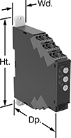 |
Safeguard your equipment against overheating, wear, and malfunction from a spike or dip in voltage. These relays continuously monitor your AC or DC power supply and trip when the voltage is outside a set range. Rated IP20, these relays have recessed terminals that keep fingers and other objects from touching live circuits. Mount them on a 35 mm DIN rail (also known as DIN 3 rail) for fast installation.
With Spring-Clamp Terminals—Relays with spring-clamp terminals connect and disconnect to wire without screws. Because there’s no screw, these connections are less likely to loosen over time, even in high-vibration environments.
Knob Adjustment—Relays with knob adjustments have knobs right on the front where you can set your trip voltage. You can see that they're wired correctly and when they're actuated based on the LED indicators. If you want to mount these relays to a surface instead of DIN rail, they have mounting holes.
No. of Terminals | Input Voltage | Trip Voltage Setting | Trip Time, sec. | Reset Type | Switching Current @ Voltage | Max. Switching Voltage | Adjustment Mechanism | Ht. | Wd. | Dp. | Features | Each | |||
|---|---|---|---|---|---|---|---|---|---|---|---|---|---|---|---|
1 Circuit Controlled with 1 Off or 1 On—SPDT | |||||||||||||||
With Spring-Clamp Terminals | |||||||||||||||
| 9 | 24V AC, 24V DC | 1V AC to 10V AC 3V AC to 30V AC 15V AC to 150V AC 1V DC to 10V DC 3V DC to 30V DC 15V DC to 150V DC | 0.1 to 30 | Automatic, Manual | 5 amp @ 240V AC 5 amp @ 30V DC | 250V AC 48V DC | Knob | 3.5" | 0.7" | 3.5" | LED Indicator | 8446N101 | 0000000 | ||
| 9 | 24V AC, 24V DC | 20V AC to 200V AC 30V AC to 300V AC 60V AC to 600V AC 20V DC to 200V DC 30V DC to 300V DC 60V DC to 600V DC | 0.1 to 30 | Automatic, Manual | 5 amp @ 240V AC 5 amp @ 30V DC | 250V AC 48V DC | Knob | 3.5" | 0.7" | 3.5" | LED Indicator | 8446N103 | 000000 | ||
| 9 | 120V AC, 240V AC | 1V AC to 10V AC 3V AC to 30V AC 15V AC to 150V AC 1V DC to 10V DC 3V DC to 30V DC 15V DC to 150V DC | 0.1 to 30 | Automatic, Manual | 5 amp @ 240V AC 5 amp @ 30V DC | 250V AC 48V DC | Knob | 3.5" | 0.7" | 3.5" | LED Indicator | 8446N102 | 000000 | ||
| 9 | 120V AC, 240V AC | 20V AC to 200V AC 30V AC to 300V AC 60V AC to 600V AC 20V DC to 200V DC 30V DC to 300V DC 60V DC to 600V DC | 0.1 to 30 | Automatic, Manual | 5 amp @ 240V AC 5 amp @ 30V DC | 250V AC 48V DC | Knob | 3.5" | 0.7" | 3.5" | LED Indicator | 8446N104 | 000000 | ||
Ground-Fault Monitoring Relays
 |  |
Screw Terminals | Screw Terminals Knob Adjustment |
 |  |
Screw Terminals with IO-Link | Spring-Clamp Terminals with IO-Link |
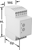
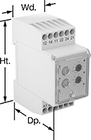
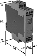
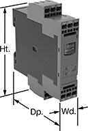
Detect and mitigate ground faults to prevent harm to equipment, circuits, and people. These relays monitor the differential between incoming and outgoing current, also known as residual current. When the balance is off, they trip and cut power to the circuit. These relays are highly sensitive, so you can trust them to de-energize faulty circuits before a minor issue becomes a major one. Rated IP20, they have recessed terminals that keep fingers and other objects from touching live circuits. Mount them on 35 mm DIN rail (also known as DIN 3 rail) for fast installation.
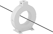
These relays require a current-indicating ring (sold separately) to operate. Choose a ring that is large enough for your lines to pass through. Feed the lines of the circuit through the center of the ring and connect the indicating ring output to the relay.
Spring-Clamp-Terminal Wire Connection—Relays with spring-clamp terminals connect and disconnect to wire without screws. Because they don’t have screws, there’s less of a risk that they will loosen over time, even when they’re under vibration.
IO-Link Communication Protocol—Relays with IO-Link can be programmed, monitored, and reset remotely by connecting them to a programmable logic controller (PLC), human-machine interface (HMI), or computer. If you want to program them locally, they have a keypad.
Knob Adjustment—Relays with knob adjustments have knobs right on the front where you can set your trip current.
LED Indicator—Relays with an LED indicator show the status of your relay, so you know it is wired correctly and when it is actuated.
No. of Terminals | Input Voltage | Trip Current Setting, amp | Trip Current, amp | Trip Time, sec. | Switching Current @ Voltage | Max. Switching Voltage | Adjustment Mechanism | Ht. | Wd. | Dp. | Features | Each | |||
|---|---|---|---|---|---|---|---|---|---|---|---|---|---|---|---|
Screw Terminals | |||||||||||||||
2 Circuits Controlled with 2 Off or 2 On—DPDT | |||||||||||||||
| 12 | 24V AC, 48V AC, 120V AC, 240V AC | 0.03 | — | 0 | 5 amp @ 240V AC 5 amp @ 24V DC | 250V AC 24V DC | — | 3.2" | 1.4" | 2.6" | LED Indicator | 8121N101 | 0000000 | ||
| 12 | 24V AC, 48V AC, 120V AC, 240V AC | 0.3 | — | 0 | 5 amp @ 240V AC 5 amp @ 24V DC | 250V AC 24V DC | — | 3.2" | 1.4" | 2.6" | LED Indicator | 8121N102 | 000000 | ||
| 12 | 24V AC, 48V AC, 120V AC, 240V AC | — | 0.03 to 5 | 0 to 5 | 5 amp @ 240V AC 5 amp @ 24V DC | 250V AC 24V DC | Knob | 3.2" | 1.4" | 2.8" | LED Indicator | 8121N103 | 000000 | ||
| 12 | 24V AC, 48V AC, 120V AC, 240V AC | — | 0.3 to 30 | 0 to 5 | 5 amp @ 240V AC 5 amp @ 24V DC | 250V AC 24V DC | Knob | 3.2" | 1.4" | 2.8" | LED Indicator | 8121N104 | 000000 | ||
Screw Terminals with IO-Link | |||||||||||||||
2 Circuits Controlled with 2 Off or 2 On—DPDT | |||||||||||||||
| 12 | 24V DC | — | 0.03 to 40 | 0 to 999 | 3 amp @ 240V AC 1 amp @ 24V DC | 400V AC 250V DC | External Controller, Keypad | 4" | 0.9" | 3.6" | Remote Reset | 8121N109 | 000000 | ||
Spring-Clamp Terminals with IO-Link | |||||||||||||||
2 Circuits Controlled with 2 Off or 2 On—DPDT | |||||||||||||||
| 12 | 24V DC | — | 0.03 to 40 | 0 to 999 | 3 amp @ 240V AC 1 amp @ 24V DC | 400V AC 250V DC | External Controller, Keypad | 4.1" | 0.9" | 3.6" | Remote Reset | 8121N111 | 000000 | ||
Frequency-Monitoring Relays
 |  |
DIN-Rail Mount | Relay-Socket Mount |
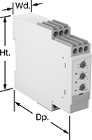
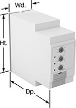
Prevent changes in frequency from damaging sensitive equipment. Often used with motors, fluorescent lighting, and controllers, these relays cut power to your device if the frequency falls outside the set range. Switches on the front of these relays let you set your trip frequency and time. You can see that they're wired correctly and when they're actuated based on the LED indicators. Rated IP20, these relays have recessed terminals that keep fingers and other objects from touching live circuits.
DIN-Rail Mount—DIN-rail mount relays snap onto 35 mm DIN rail (also known as DIN 3 rail) for fast installation.
Relay-Socket Mount—Relay-socket mount relays plug into a socket (sold separately), which is required for installation.
Monitoring Relays | Sockets | |||||||||||||||||
|---|---|---|---|---|---|---|---|---|---|---|---|---|---|---|---|---|---|---|
Trip Frequency Setting, Hz | ||||||||||||||||||
No. of Terminals | Input Voltage, V AC | 50 Hz Input | 60 Hz Input | Trip Time, sec. | Reset Type | Switching Current @ Voltage | Max. Switching Voltage | Adjustment Mechanism | Ht. | Wd. | Dp. | Features | Each | Each | ||||
1 Circuit Controlled with 1 Off or 1 On—SPDT | ||||||||||||||||||
DIN-Rail Mount | ||||||||||||||||||
| 9 | 24, 48, 120, 240 | 40 to 60 48 to 52 | 50 to 70 58 to 62 | 0.1 to 30 | Automatic, Manual | 8 amp @ 240V AC 5 amp @ 24V DC | 250V AC 24V DC | DIP Switch | 3.1" | 0.9" | 3.9" | LED Indicator | 8477N11 | 0000000 | ——— | 0 | ||
Relay-Socket Mount | ||||||||||||||||||
| 1 | 24, 48, 120, 240 | 40 to 60 48 to 52 | 50 to 70 58 to 62 | 0.1 to 30 | Automatic, Manual | 8 amp @ 240V AC 5 amp @ 24V DC | 250V AC 24V DC | DIP Switch | 3.1" | 1.4" | 3.7" | LED Indicator | 8477N12 | 000000 | 7122K12 | 000000 | ||
