


Safety Relays
Receive signals from safety monitoring relays or controllers to switch devices off and on because of a system failure. Also known as force-guided or mechanically linked contacts, the interlocking opposing contacts on these relays cannot be open or closed at the same time. To keep your system from receiving false switching signals, the interlocking opposing contact must remain open even if a contact welds closed.
IP20 rated, they have recessed terminals that prevent fingers and other objects from touching live circuits. These relays have been tested to safety standards that can help you achieve your system's PL (performance level) and SIL (safety integrity level). Choose a relay with a PL and SIL rating to meet the needs of your system. Higher ratings indicate greater safety protection. As your system becomes more complex, you generally require a higher safety protection level. Mount them to 35mm DIN rail (also known as DIN 3 Rail).
Relays that meet SIL2 are tested for applications with a probability of failure of 0.1% to 1%. They’re often used for emergency shutdowns, and fire, gas, and overpressure detection.
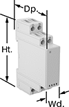
| Number of Terminals | Input Voltage | Control Current, mA | Switching Current @ Voltage | Max. Switching Voltage | Ht. | Wd. | Dp. | Features | Each | |
With Screw Terminals—DIN-Rail Mount | ||||||||||
|---|---|---|---|---|---|---|---|---|---|---|
6 Circuits Controlled with 4 Off (Normally Open) and 2 On (Normally Closed)—6PDT-4NO/2NC | ||||||||||
| 16 | 120V AC | 10 | 6 A @ 240 V AC | 250V AC | 3.4" | 0.9" | 3.9" | Interlocked Opposing Contacts, Recessed Terminals, LED Indicator | 6242N118 | 0000000 |
| 16 | 24V DC | 42 | 6 A @ 240 V AC | 250V AC | 3.4" | 0.9" | 3.9" | Interlocked Opposing Contacts, Recessed Terminals, LED Indicator | 6242N119 | 000000 |