


Filter by
System of Measurement
Switch Designation
Switch Starting Position
Number of Circuits Controlled
Switch Action

Electrical Phase
Relay Type

Operation Type
Switch 2nd Signal Starting Position
Certification
Wire Connection

Actuator Style


DFARS Specialty Metals
Export Control Classification Number (ECCN)
U.S.–Mexico–Canada Agreement (USMCA) Qualifying
Mechanical Life Cycles
Sequenced Latching Relays
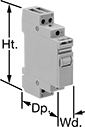 |
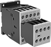
These relays switch through a series of different circuit configurations every time they receive an input voltage. The input voltage latches them in position, so they don’t require a constant voltage to stay switched. Use them to control motors, pumps, and lighting. The covered terminals prevent contact with live connections. Mount to 35 mm DIN rail. Also known as step relays.
Switch Starting Position | Input Voltage | Control Power | Switching Current @ Voltage | Max. Switching Voltage, V AC | hp @ Switching Voltage | Ht. | Wd. | Dp. | Each | |||
|---|---|---|---|---|---|---|---|---|---|---|---|---|
2 Circuits Controlled—DPST-1NO/1NC | ||||||||||||
6 Terminals | ||||||||||||
| 1st Signal—1 Off and 1 On 2nd Signal—1 Off and 1 On | 24V AC | 6.5 VA | 16 amp @ 120V AC | 277 | 1/2 hp @ 120V AC | 3.3" | 0.7" | 2.4" | 6784T131 | 000000 | ||
| 1st Signal—1 Off and 1 On 2nd Signal—1 Off and 1 On | 120V AC | 6.5 VA | 16 amp @ 120V AC | 277 | 1/2 hp @ 120V AC | 3.3" | 0.7" | 2.4" | 6784T132 | 00000 | ||
| 1st Signal—1 Off and 1 On 2nd Signal—1 Off and 1 On | 240V AC | 6.5 VA | 16 amp @ 120V AC | 277 | 1/2 hp @ 120V AC | 3.3" | 0.7" | 2.4" | 6784T133 | 00000 | ||
| 1st Signal—1 Off and 1 On 2nd Signal—1 Off and 1 On | 12V DC | 5 W | 16 amp @ 120V AC | 277 | 1/2 hp @ 120V AC | 3.3" | 0.7" | 2.4" | 6784T134 | 00000 | ||
| 1st Signal—1 Off and 1 On 2nd Signal—1 Off and 1 On | 24V DC | 5 W | 16 amp @ 120V AC | 277 | 1/2 hp @ 120V AC | 3.3" | 0.7" | 2.4" | 6784T135 | 00000 | ||
Safety Relays
SIL 2, PLd Max. System Safety Rating—DIN-Rail Mount
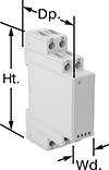 |
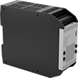
Relays that meet SIL 2 are tested for applications with a probability of failure of 0.1% to 1%. They’re often used for emergency shutdowns, and fire, gas, and overpressure detection.
No. of Terminals | Input Voltage | Control Current, mA | Switching Current @ Voltage | Max. Switching Voltage, V AC | Ht. | Wd. | Dp. | Features | Each | |||
|---|---|---|---|---|---|---|---|---|---|---|---|---|
Screw-Terminal Wire Connection | ||||||||||||
2 Circuits Controlled with 1 Off and 1 On—DPST-1NO/1NC | ||||||||||||
| 8 | 120V AC | 9 | 6 amp @ 240V AC | 250 | 3.4" | 0.9" | 3.9" | Interlocked Opposing Contacts, LED Indicator, Recessed Terminals | 6242N112 | 000000 | ||
| 8 | 24V DC | 38 | 6 amp @ 240V AC | 250 | 3.4" | 0.9" | 3.9" | Interlocked Opposing Contacts, LED Indicator, Recessed Terminals | 6242N113 | 00000 | ||
Interface Safety Relays
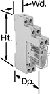 |
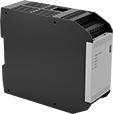
These relays pair the transmission reliability of an interface relay with the fail-safe operation of a safety relay. Use them to communicate signals to devices like motors or sensors. They have interlocking contacts—also known as force-guided or mechanically linked contacts—so opposing contacts won't close at the same time. This minimizes the chance of arcing, so electricity won't jump across the contacts and interfere with your relay or system. They also have an interface that isolates input and output circuits to prevent damage from voltage spikes, reduce signal interference, and amplify signal. Mount them on 35 mm DIN rail (also known as DIN 3 rail). The relays disconnect from the socket for quick replacement.
LED Indicator—Relays with LED indicator light up when the relay is on, so you’ll know it’s wired correctly and can tell at a glance whether it’s on or off.
Safety Relays | Replacement Safety Relays | ||||||||||||||
|---|---|---|---|---|---|---|---|---|---|---|---|---|---|---|---|
No. of Terminals | Input Voltage, V DC | Control Current, mA | Switching Current @ Voltage | Max. Switching Voltage | Mechanical Life Cycles | Ht. | Wd. | Dp. | Features | Each | Each | ||||
2 Circuits Controlled with 1 Off and 1 On—DPST-1NO/1NC | |||||||||||||||
| 6 | 12 | 63 | 3 amp @ 240V AC/24V DC | 250V AC, 125V DC | 10,000,000 | 1.1" | 0.5" | 1.1" | Interlocked Opposing Contacts, LED Indicator | 8722N12 | 000000 | 8722N13 | 000000 | ||
Two-Hand Push-Button Safety Switches
 |
It takes two hands to activate these switches, minimizing the risk of accidental equipment start-up. They have an emergency stop push-button to immediately cut power. They’re rated IP65 for protection from low-pressure washdowns.
Switches with push-button actuators require a safety relay (sold separately) for a complete system.
Actuator | Mounting | |||||||||||||||
|---|---|---|---|---|---|---|---|---|---|---|---|---|---|---|---|---|
No. of Circuits Controlled | Switch Starting Position | Switch Action | Switch Designation | Material | Color | Switching Current @ Voltage | Ht. | Wd. | Dp. | No. of Holes | Hole Dia. | Fasteners Included | Features | Each | ||
| 2 | 1 Off and 1 On | Momentary | DPST-1NO/1NC | Plastic | Black | 8 amp @ 250V AC, 5 amp @ 24V DC | 7 5/16" | 18 1/2" | 5 7/16" | 2 | 29/64" | No | Emergency Stop Button | 65945K71 | 0000000 | |
 |
Input Voltage, V DC | No. of Terminals | Switching Current @ Voltage | For DIN Rail Ht., mm | Wire Connection | Features | Each | |||
|---|---|---|---|---|---|---|---|---|---|
2 Circuits Controlled with 1 Off and 1 On Switch Starting Position—DPST-1NO/1NC | |||||||||
| 24 | 12 | 5.5 amp @ 24V DC | 35 | Screw Terminal | Self-Monitoring Circuitry | 65945K72 | 0000000 | ||
Two-Hand Finger-Touch Safety Switches
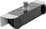 |
It takes two hands to activate these switches, minimizing the risk of accidental equipment start-up. They have an emergency stop push-button to immediately cut power. They’re rated IP65 for protection from low-pressure washdowns.
Switches turn circuits on and off with a light touch, even when wearing gloves. An infrared sensor detects the lightest finger contact, and an indicator lights up to confirm when they are activated. Because they don't require you to press down a button to operate, they meet ANSI B11.TR1 standards to reduce hand, wrist, and arm fatigue. You'll need a relay or controller to complete your system—upgrade to a controller if you plan to operate additional devices beyond your switch.
Actuator | Mounting Holes | |||||||||||||||
|---|---|---|---|---|---|---|---|---|---|---|---|---|---|---|---|---|
No. of Circuits Controlled | Switch Starting Position | Switch Action | Switch Designation | Material | Color | Switching Current @ Voltage | Ht. | Wd. | Dp. | No. of | Dia. | Mounting Fasteners Included | Features | Each | ||
| 2 | 1 Off and 1 On | Momentary | DPST-1NO/1NC | Plastic | Black | 0.15 amp @ 24V DC | 3 7/16" | 18 11/16" | 5 1/2" | 4 | 5/16" | No | Emergency Stop Button Output Indicator Power Indicator | 65945K41 | 0000000 | |
 |
hp @ Switching Voltage | |||||||||||||
|---|---|---|---|---|---|---|---|---|---|---|---|---|---|
Input Voltage, V DC | No. of Terminals | Switching Current @ Voltage | Single Phase | Three Phase | Aux. Contact Switch Starting Position | For DIN Rail Size, mm | Wire Connection | Features | Max. System Safety Rating | Each | |||
3 3 Off Switch Starting Position—3PST-NO | |||||||||||||
| 24 | 18 | 9 amp @ 400V AC | 1/2 hp @ 120V AC 1 1/2 hp @ 240V AC | 3 hp @ 240V AC 5 hp @ 480V AC 7 1/2 hp @ 600V AC | 2 Off and 3 On | 35 | Screw Terminal | Inspection Window, Interlocked Opposing Contacts, Mirror Auxiliary Contacts, Nondetachable Auxiliary Contacts, Recessed Terminals, Self-Monitoring Circuitry | CAT IV, 600V; PLe; SIL 3 | 6242N16 | 0000000 | ||
 |  |  |
With Micro USB-B 2.0 Connection | With Micro USB-B 2.0 and RJ45 Ethernet Connection | LCD Display |
No. of Inputs | Input Voltage, V DC | Signal Output | Control Communication Protocol | For Max. No. of Expansion Modules | Ht. | Wd. | Dp. | Digital Display Type | Each | |||
|---|---|---|---|---|---|---|---|---|---|---|---|---|
Female Micro USB-B 2.0 Connection | ||||||||||||
| 26 | 24 | PNP | — | 8 | 4 5/16" | 1 3/4" | 5 1/16" | LCD | 65945K46 | 000000000 | ||
Female Micro USB-B 2.0 Connection and Female RJ45 Ethernet Connection | ||||||||||||
| 26 | 24 | PNP | EtherNet/IP, Modbus TCP/IP, Profinet | 8 | 4 5/16" | 1 3/4" | 5 1/16" | — | 65945K47 | 00000000 | ||
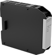 |
Safety Controller Expansion Modules |
Input Voltage, V DC | No. of Outputs | Signal Output | Ht. | Wd. | Dp. | Each | ||
|---|---|---|---|---|---|---|---|---|
| 24 | 4 | PNP | 4 5/16" | 1" | 5 1/16" | 65945K48 | 0000000 |
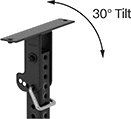 | 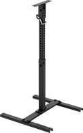 |
30° Tilt Range of Motion | Telescoping Stands |
Base Mounting Holes | Head Mounting Holes | ||||||||||||
|---|---|---|---|---|---|---|---|---|---|---|---|---|---|
Ht. | Wd. | Dp. | Head Movement | Tilt Range of Motion | Material | No. of | Dia. | No. of | Dia. | Mounting Fasteners Included | Each | ||
| 31 1/2" to 48 1/2" | 24 1/16" | 24" | Tilt | 30° | Steel | 4 | 29/64" | 2 | 5/16" | Yes | 65945K44 | 0000000 | |
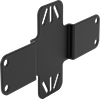 |
Mounting Brackets |
Mounting Holes | |||||||||
|---|---|---|---|---|---|---|---|---|---|
Ht. | Wd. | Dp. | Material | No. of | Dia. | Mounting Fasteners Included | Each | ||
| 5 15/16" | 10 1/4" | 3/8" | Steel | 4 | 3/8" | Yes | 65945K45 | 000000 | |
 |
Wire Leads | ||||||||||||
|---|---|---|---|---|---|---|---|---|---|---|---|---|
Input Voltage, V DC | Signal Output | Ht. | Wd. | Dp. | Thread Size | Cable Lg., ft. | No. of | Lg., ft. | Features | Each | ||
| 10 to 30 | PNP | 2 5/16" | 2 3/8" | 1 11/16" | M30 × 1.5 mm | 1 | 4 | 1 | Output Indicator, Power Indicator | 65945K43 | 0000000 | |
