



























Filter by
Product Family
Input Voltage

Switching Voltage
Switching Current
Mounting Location
Socket Connection


Operation Type


Wire Connection
Electrical Connection
Switch Starting Position
Horsepower @ Switching Voltage
Switch Action
U.S.–Mexico–Canada Agreement (USMCA) Qualifying
DFARS Specialty Metals
Export Control Classification Number (ECCN)
DIN-Rail Mount Solid State Relays
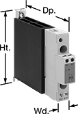 | 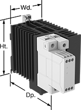 | 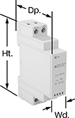 |
Relay with Integrated Heat Sink | Relay with Integrated Heat Sink and Fan | Relay |
Unlike mechanical relays, these solid state relays have no moving parts, so they require less maintenance and last longer, switch faster, and are quieter. They mount on 35 mm DIN rail (also known as DIN 3) for fast installation. An LED indicator lights up when these relays are connected, so you can quickly confirm that they’re wired correctly. IP20 rated, their terminals are recessed, so they prevent fingers and other objects from touching live circuits.
Integrated Heat Sink—Relays with an integrated heat sink disperse heat to increase the relay’s current rating.
No. of Terminals | Input Voltage | Control Current, mA | Switching Current @ Voltage (Load Type) | Max. Switching Voltage, V AC | Ht. | Wd. | Dp. | Features | Each | |||
|---|---|---|---|---|---|---|---|---|---|---|---|---|
1 Circuit Controlled with 1 Off—SPST-NO | ||||||||||||
Single Phase | ||||||||||||
| 4 | 24V AC, 90V AC, 120V AC, 240V AC, 24V DC, 48V DC, 60V DC, 120V DC, 275V AC | 12 | 5 amp @ 24V AC (Full) 10 amp @ 24V AC (Resistive) 10 amp @ 240V AC | 240 | 4.173" | 0.7" | 2.56" | Integrated Heat Sink, LED Indicator | 8299K34 | 000000 | ||
Thin Spade-Terminal Relays
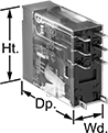 |  |  |
8-Terminal Relay | Sockets with Spring-Clamp Terminals | Sockets with Screw Terminals |
Save space in your control cabinet. These narrow relays are often used for low-current switching applications, such as on small motors and pilot lights. They plug into a socket (sold separately) for quick installation.
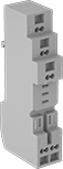
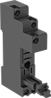
Relay sockets mount directly on 35 mm DIN rail (also known as DIN 3 rail). Those with screw terminals connect and disconnect wire when you turn the screws. They can also mount to a flat surface. Those with spring-clamp terminals connect and disconnect to wires without needing to turn screws. Insert a screwdriver into the slot to release the spring clamp holding the wire in place.
Relays | Sockets with Screw Terminals | Sockets with Spring-Clamp Terminals | |||||||||||||||
|---|---|---|---|---|---|---|---|---|---|---|---|---|---|---|---|---|---|
No. of Terminals | Input Voltage | Control Current, mA | Switching Current @ Voltage | Max. Switching Voltage, V AC | hp @ Switching Voltage | Ht. | Wd. | Dp. | Quick-Disconnect Tab Wd. | Each | Each | Each | |||||
2 Circuits Controlled with 2 Off or 2 On—DPDT | |||||||||||||||||
Relay-Socket Mount | |||||||||||||||||
| 8 | 24V AC | 44 | 5 amp @ 120V AC/24V DC | 380 | 1/6 hp @ 120V AC | 1.1" | 0.5" | 1.4" | 0.098" | 7098K28 | 000000 | 7098K22 | 000000 | 7098K24 | 000000 | ||
| 8 | 120V AC | 8 | 5 amp @ 120V AC/24V DC | 380 | 1/6 hp @ 120V AC | 1.1" | 0.5" | 1.4" | 0.098" | 7098K15 | 00000 | 7098K22 | 00000 | 7098K24 | 00000 | ||
| 8 | 240V AC | 4 | 5 amp @ 120V AC/24V DC | 380 | 1/6 hp @ 120V AC | 1.1" | 0.5" | 1.4" | 0.098" | 7098K16 | 00000 | 7098K22 | 00000 | 7098K24 | 00000 | ||
| 8 | 6V DC | 87 | 5 amp @ 120V AC/24V DC | 380 | 1/6 hp @ 120V AC | 1.1" | 0.5" | 1.4" | 0.098" | 7098K69 | 0000 | 7098K22 | 00000 | 7098K24 | 00000 | ||
| 8 | 12V DC | 43 | 5 amp @ 120V AC/24V DC | 380 | 1/6 hp @ 120V AC | 1.1" | 0.5" | 1.4" | 0.098" | 7098K27 | 0000 | 7098K22 | 00000 | 7098K24 | 00000 | ||
| 8 | 24V DC | 22 | 5 amp @ 120V AC/24V DC | 380 | 1/6 hp @ 120V AC | 1.1" | 0.5" | 1.4" | 0.098" | 7098K14 | 0000 | 7098K22 | 00000 | 7098K24 | 00000 | ||
Relay Sockets
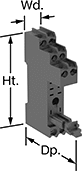 | 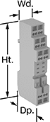 |
Style H | Style K |
Mount to 35 mm DIN rail (also known as DIN 3 rail) or flat surfaces, then plug your relay into these sockets for fast installation.
Spring-Clamp-Terminal Wire Connection—Relay sockets with spring-clamp-terminal wire connections connect and disconnect to wires without needing to turn screws. By avoiding screws, these terminals reduce the risk that connections will shake loose over time, even in high vibration environments.
Recessed Terminals—Recessed terminals prevent contact with live connections.
Style | No. of Terminals | For Quick-Disconnect Tab Wd. | For Switching Current @ Voltage | For Max. Switching Voltage, V AC | Ht. | Wd. | Dp. | Features | Each | |||
|---|---|---|---|---|---|---|---|---|---|---|---|---|
Quick-Disconnect-Terminal Relay Connection | ||||||||||||
Screw-Terminal Wire Connection | ||||||||||||
| H | 8 | 0.098" | 5 amp @ 120V AC | 380 | 3.1" | 0.6" | 2.4" | Recessed Terminals | 7098K22 | 000000 | ||
Spring-Clamp-Terminal Wire Connection | ||||||||||||
| K | 8 | 0.098" | 5 amp @ 120V AC | 380 | 3.6" | 0.71" | 1.5" | — | 7098K24 | 00000 | ||
Solid State Screw Terminal Relays
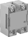 | 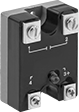 | 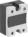 |
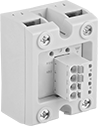
1-Circuit Relay with Covered Terminals and LED Indicator | 1-Circuit Relay with LED Indicator | 1-Circuit Relay with Covered Terminals |
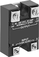 |  |  |
1-Circuit Relay | 2-Circuit Relay | Heat Sinks |
With no moving parts, these solid-state relays are fast switching and require less maintenance, last longer, and are quieter than mechanical switches.
High-Starting-Current Protection—Relays with high-starting-current protection are designed with integrated circuits that prevent damage from the large burst of electricity when a device, such as a motor or pump, turns on.
LED Indicator—Relays with LED indicator let you quickly spot whether a relay is on or off.
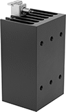
Heat Sinks—Heat sinks disperse heat to increase the relay’s current rating. Mount them to 35 mm DIN rail (also known as DIN 3 rail) for fast installation. They also mount to flat surfaces. Before mounting one-circuit relays, silicone compound or a thermal pad should be placed between the heat sink and relay. Silicone compound is sold separately for heat sinks that do not include it but require it. Two-circuit relays don’t require silicone for mounting.
Relays | Heat Sinks | Silicone Compounds | ||||||||||||||
|---|---|---|---|---|---|---|---|---|---|---|---|---|---|---|---|---|
Switching Current @ Voltage | ||||||||||||||||
No. of Terminals | Input Voltage | Without Heat Sink | With Heat Sink, amp | Max. Switching Voltage, V AC | Ht. | Wd. | Dp. | Enclosure Rating | Each | Each | Each | |||||
1 Circuit Controlled with 1 Off—SPST-NO | ||||||||||||||||
Relays with High-Starting-Current Protection | ||||||||||||||||
| 4 | 85V AC, 120V AC, 240V AC, 280V AC | 5 amp @ 120V AC | 10 | 140 | 2.3" | 1.8" | 1" | — | 7456K125 | 000000 | 7456K222 | 000000 | 10405K79 | 000000 | ||
| 4 | 85V AC, 120V AC, 240V AC, 280V AC | 5 amp @ 240V AC | 10 | 280 | 2.3" | 1.8" | 1" | — | 7456K126 | 00000 | 7456K222 | 00000 | 10405K79 | 00000 | ||
| 4 | 3V DC, 6V DC, 12V DC, 24V DC, 30V DC | 5 amp @ 120V AC | 10 | 140 | 2.3" | 1.8" | 1" | — | 7456K127 | 00000 | 7456K222 | 00000 | 10405K79 | 00000 | ||
| 4 | 3V DC, 6V DC, 12V DC, 24V DC, 30V DC | 5 amp @ 240V AC | 10 | 280 | 2.3" | 1.8" | 1" | — | 7456K128 | 00000 | 7456K222 | 00000 | 10405K79 | 00000 | ||
Relays with High-Starting-Current Protection and Covered Terminals | ||||||||||||||||
| 4 | 24V AC, 48V AC, 120V AC, 240V AC, 24V DC, 48V DC | 5 amp @ 240V AC | 50 | 265 | 2.3" | 1.8" | 1.1" | IP20 | 7456K64 | 00000 | 7456K33 | 00000 | ——— | 0 | ||
| 4 | 24V AC, 48V AC, 120V AC, 240V AC, 24V DC, 48V DC | 5 amp @ 480V AC | 50 | 530 | 2.3" | 1.8" | 1.1" | IP20 | 7456K108 | 00000 | 7456K33 | 00000 | ——— | 0 | ||
| 4 | 24V AC, 48V AC, 120V AC, 240V AC, 24V DC, 48V DC | 5 amp @ 600V AC | 50 | 660 | 2.3" | 1.8" | 1.1" | IP20 | 7456K117 | 000000 | 7456K33 | 00000 | ——— | 0 | ||
| 4 | 3V DC, 6V DC, 12V DC, 24V DC, 30V DC | 5 amp @ 240V AC | 50 | 265 | 2.3" | 1.8" | 1.1" | IP20 | 7456K63 | 00000 | 7456K33 | 00000 | ——— | 0 | ||
| 4 | 4V DC, 6V DC, 12V DC, 24V DC, 30V DC | 5 amp @ 480V AC | 50 | 530 | 2.3" | 1.8" | 1.1" | IP20 | 7456K107 | 00000 | 7456K33 | 00000 | ——— | 0 | ||
| 4 | 4V DC, 6V DC, 12V DC, 24V DC, 30V DC | 5 amp @ 600V AC | 50 | 660 | 2.3" | 1.8" | 1.1" | IP20 | 7456K116 | 000000 | 7456K33 | 00000 | ——— | 0 | ||
Relays with High-Starting-Current Protection and LED Indicator | ||||||||||||||||
| 4 | 3V DC, 6V DC, 12V DC, 24V DC, 30V DC | 5 amp @ 240V AC | 10 | 280 | 2.3" | 1.8" | 1" | — | 7456K129 | 00000 | 7456K222 | 00000 | 10405K79 | 00000 | ||
2 Circuits Controlled with 2 Off—DPST-NO | ||||||||||||||||
Relays with High-Starting-Current Protection and Covered Terminals and LED Indicator | ||||||||||||||||
| 6 | 4V DC, 6V DC, 12V DC, 24V DC, 30V DC | 5 amp @ 600V AC | 50 | 660 | 2.3" | 1.8" | 1.3" | IP20 | 7456K87 | 000000 | 7456K89 | 000000 | ——— | 0 | ||
2 Circuits Controlled with 2 Off—SPST-NO | ||||||||||||||||
Relays with High-Starting-Current Protection and Covered Terminals and LED Indicator | ||||||||||||||||
| 8 | 4V DC, 6V DC, 12V DC, 24V DC, 30V DC | 5 amp @ 600V AC | 50 | 660 | 2.3" | 1.8" | 1.3" | IP20 | 7456K85 | 000000 | 7456K89 | 000000 | ——— | 0 | ||
Circuit Board Relays
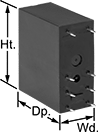 | 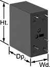 | 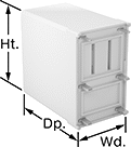 | 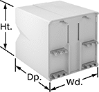 |
8 Terminals | 5 Terminals | 6 Terminals | 14 Terminals |
No. of Terminals | Input Voltage | Control Current, mA | Switching Current @ Voltage | Max. Switching Voltage | Mechanical Life Cycles | Ht. | Wd. | Dp. | Pin Lg. | Each | |||
|---|---|---|---|---|---|---|---|---|---|---|---|---|---|
Mechanical Operation | |||||||||||||
2 Circuits Controlled with 2 Off or 2 On—DPDT | |||||||||||||
| 8 | 5V DC | 106 | 5 amp @ 240V AC/30V DC | 380V AC/125V DC | 10,000,000 (AC Voltage) 20,000,000 (DC Voltage) | 1.1" | 0.5" | 1" | 0.16" | 7098K36 | 00000 | ||
| 8 | 12V DC | 44 | 5 amp @ 240V AC/30V DC | 380V AC/125V DC | 10,000,000 (AC Voltage) 20,000,000 (DC Voltage) | 1.1" | 0.5" | 1" | 0.16" | 7098K33 | 0000 | ||
| 8 | 24V DC | 22 | 5 amp @ 240V AC/30V DC | 380V AC/125V DC | 10,000,000 (AC Voltage) 20,000,000 (DC Voltage) | 1.1" | 0.5" | 1" | 0.16" | 7098K34 | 0000 | ||
Solid State Spade-Terminal Relays
Surface Mount
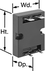 | 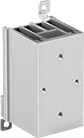 |
Surface Mount | Heat Sinks |
Heat Sinks—Heat sinks disperse heat to increase the relay’s current rating. Mount to 35 mm DIN rail (also known as DIN 3 rail) for fast installation. They also mount to flat surfaces.
Relays | Heat Sinks | ||||||||||||||
|---|---|---|---|---|---|---|---|---|---|---|---|---|---|---|---|
Switching Current @ Voltage | Quick-Disconnect Tab Wd. | ||||||||||||||
No. of Terminals | Input Voltage, V DC | Without Heat Sink | With Heat Sink, amp | Max. Switching Voltage, V AC | Ht. | Wd. | Dp. | Control Terminal | Load Terminal | Each | Each | ||||
1 Circuit Controlled with 1 Off—SPST-NO | |||||||||||||||
| 4 | 5 | 5 amp @ 240V AC | — | 240 | 1.9" | 1.5" | 0.9" | 0.11" | 0.25" | 8192K211 | 000000 | ——— | 0 | ||
| 4 | 5 | 5 amp @ 240V AC | 10 | 240 | 1.9" | 1.5" | 0.9" | 0.11" | 0.25" | 8192K221 | 00000 | 8192K31 | 000000 | ||
| 4 | 12 | 5 amp @ 240V AC | — | 240 | 1.9" | 1.5" | 0.9" | 0.11" | 0.25" | 8192K212 | 00000 | ——— | 0 | ||
| 4 | 12 | 5 amp @ 240V AC | 10 | 240 | 1.9" | 1.5" | 0.9" | 0.11" | 0.25" | 8192K222 | 00000 | 8192K31 | 00000 | ||
| 4 | 24 | 5 amp @ 240V AC | — | 240 | 1.9" | 1.5" | 0.9" | 0.11" | 0.25" | 8192K213 | 00000 | ——— | 0 | ||
| 4 | 24 | 5 amp @ 240V AC | 10 | 240 | 1.9" | 1.5" | 0.9" | 0.11" | 0.25" | 8192K223 | 00000 | 8192K31 | 00000 | ||
Safety Relays with Diagnostic Capabilities
 |
Relay |
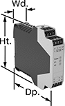
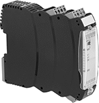
Control and diagnose issues with safety-critical circuits. These relays have a microprocessor that monitors safety components, such as emergency stops and light curtains, and sends a signal to stop the operation if a failure is detected and restart when the issue is resolved. They also help with diagnostic tasks because of their feedback circuit, which allows basic relays to communicate their status back to the safety relay. These relays have a duplicate set of input and output signals, so they’ll still stop the controlled device if one of the inputs fails.
IP20 rated, they have recessed terminals which prevent fingers and other objects from touching live circuits. These relays have been tested to multiple safety standards and can help achieve PL, SIL, or CAT system ratings. They also meet ISO and IEC standards for machine safety.
Mount them to 35 mm DIN rail (also known as DIN 3 Rail) for fast installation.
No. of Terminals | Input Voltage | Switching Current @ Voltage | Max. Switching Voltage | Ht. | Wd. | Dp. | For Use With | Mounting Location | Max. System Safety Rating | Each | |||
|---|---|---|---|---|---|---|---|---|---|---|---|---|---|
2 Circuits Controlled | |||||||||||||
2 Safety Outputs with 2 Off and 1 Signal Output with 2 On | |||||||||||||
| 16 | 24V AC, 24V DC | 5 amp @ 240V AC 5 amp @ 24V DC | 250V AC, 250V DC | 3.9" | 0.9" | 4.5" | Two-Hand Switches | DIN Rail | PLe, SIL 3 | 6322N16 | 0000000 | ||
3 Safety Outputs with 2 Off and 1 Signal Output with 2 On | |||||||||||||
| 24 | 24V AC, 48V AC, 120V AC, 240V AC, 24V DC, 48V DC, 60V DC, 120V DC, 240V DC | 5 amp @ 240V AC 5 amp @ 24V DC | 250V AC, 250V DC | 4.42" | 0.9" | 4.5" | Emergency Stops | DIN Rail | PLe, SIL 3 | 6322N14 | 00000000 | ||
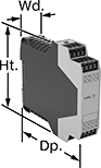 | 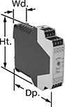 |
Auxiliary Contact Block | Auxiliary Contact Block with Time Delay |
No. of Terminals | Input Voltage, V DC | Switching Current @ Voltage | Max. Switching Voltage | Ht. | Wd. | Dp. | Features | Each | |||
|---|---|---|---|---|---|---|---|---|---|---|---|
5 Safety Outputs | |||||||||||
| 16 | 24 | 3 amp @ 240V AC 2.5 amp @ 24V DC | 250V AC, 250V DC | 3.9" | 0.9" | 4.5" | — | 6322N22 | 0000000 | ||
4 Delayed Safety Outputs | |||||||||||
| 16 | 24 | 3 amp @ 240V AC 3 amp @ 24V DC | 250V AC, 250V DC | 3.9" | 0.9" | 4.5" | Time Delay | 6322N18 | 000000 | ||
Solid State Versa-Mount Timer Relays
 |
 |
Sockets |
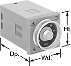
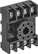
Mount these timer relays in a panel cutout or plug them into a relay socket for quick installation. Capable of fast switching, they are solid state and have no moving parts, so they require less maintenance, last longer, and are quieter than mechanical relays. Unlike standard relays that switch on and off immediately, timer relays delay before the circuit stops or starts.
Delayed Off—Delayed off relays let you set how long it takes for the relay to turn off after input voltage is removed. For example, a sensor detects when an item has been placed on a conveyor, triggering the relay to start the conveyor belt and a cooling fan. After the item has moved past another sensor, the input voltage is removed to stop the conveyor, while the cooling fan runs for a set time before shutting off.
Repeat Cycle—Relays with a repeat cycle alternate between an on cycle and off cycle of equal durations until input voltage is removed. A common example would be a flashing light.
Asymmetrical Repeat Cycle—Relays with an asymmetrical repeat cycle begin in an on state, then alternate between different durations of off and on for as long as input voltage is applied. For example, a heating system starts with an on period, then switches to an off period once the desired temperature is reached.
Start-Off Asymmetrical Repeat Cycle—Relays with a start-off asymmetrical repeat cycle begin in an off state, then alternate between different durations of on and off for as long as input voltage is applied. For example, an irrigation system receives a signal and starts in the off state, allowing water to fill before switching on to start pumping.
Sockets—Relay sockets (sold separately) mount to 35 mm DIN rail (also known as DIN 3 rail) or can be mounted to a flat surface.
Timer Relays | Sockets | |||||||||||||
|---|---|---|---|---|---|---|---|---|---|---|---|---|---|---|
Timing Range | ||||||||||||||
No. of Terminals | Input Voltage | Control Current, mA | No. of | Overall | Switching Current @ Voltage | Ht. | Wd. | Dp. | Each | Each | ||||
Delayed Off | ||||||||||||||
2 Circuits Controlled with 2 Off or 2 On—DPDT | ||||||||||||||
| 8 | 120V AC | 2 | 4 | 0.05 sec. to 12 sec. | 5 amp @ 240V AC | 1.9" | 1.9" | 2.74" | 69695K74 | 0000000 | 7122K19 | 00000 | ||
| 8 | 120V AC | 2 | 4 | 3 sec. to 12 min. | 5 amp @ 240V AC | 1.9" | 1.9" | 2.74" | 69695K73 | 000000 | 7122K19 | 0000 | ||
Repeat Cycle | ||||||||||||||
2 Circuits Controlled with 2 Off or 2 On—DPDT | ||||||||||||||
| 8 | 120V AC, 240V AC, 110V DC, 120V DC | 100 | 4 | 0.05 sec. to 300 hr. | 5 amp @ 240V AC | 1.9" | 1.9" | 3.3" | 69695K72 | 000000 | 7122K19 | 0000 | ||
Asymmetrical Repeat Cycle | ||||||||||||||
2 Circuits Controlled with 2 Off or 2 On—DPDT | ||||||||||||||
| 8 | 24V AC, 48V AC, 12V DC, 24V DC, 48V DC | 83 | 4 | 0.05 sec. to 300 hr. | 5 amp @ 240V AC | 1.9" | 1.9" | 3.3" | 69695K114 | 000000 | 7122K19 | 0000 | ||
| 8 | 120V AC, 240V AC, 110V DC, 120V DC | 41 | 4 | 0.05 sec. to 300 hr. | 5 amp @ 240V AC | 1.9" | 1.9" | 3.3" | 69695K113 | 000000 | 7122K19 | 0000 | ||
| 11 | 24V AC, 48V AC, 12V DC, 24V DC, 48V DC | 83 | 4 | 0.05 sec. to 300 hr. | 5 amp @ 240V AC | 1.9" | 1.9" | 3.3" | 8934N14 | 000000 | 7122K21 | 0000 | ||
| 11 | 120V AC, 240V AC, 110V DC, 120V DC | 41 | 4 | 0.05 sec. to 300 hr. | 5 amp @ 240V AC | 1.9" | 1.9" | 3.3" | 8934N13 | 000000 | 7122K21 | 0000 | ||
Start-Off Asymmetrical Repeat Cycle | ||||||||||||||
2 Circuits Controlled with 2 Off or 2 On—DPDT | ||||||||||||||
| 8 | 24V AC, 48V AC, 12V DC, 24V DC, 48V DC | 83 | 4 | 0.05 sec. to 300 hr. | 5 amp @ 240V AC | 1.9" | 1.9" | 3.3" | 69695K112 | 000000 | 7122K19 | 0000 | ||
| 8 | 120V AC, 240V AC, 110V DC, 120V DC | 41 | 4 | 0.05 sec. to 300 hr. | 5 amp @ 240V AC | 1.9" | 1.9" | 3.3" | 69695K111 | 000000 | 7122K19 | 0000 | ||
| 11 | 24V AC, 48V AC, 12V DC, 24V DC, 48V DC | 83 | 4 | 0.05 sec. to 300 hr. | 5 amp @ 240V AC | 1.9" | 1.9" | 3.3" | 8934N12 | 000000 | 7122K21 | 0000 | ||
| 11 | 120V AC, 240V AC, 110V DC, 120V DC | 41 | 4 | 0.05 sec. to 300 hr. | 5 amp @ 240V AC | 1.9" | 1.9" | 3.3" | 8934N111 | 000000 | 7122K21 | 0000 | ||
 |
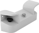
Mounting brackets are required to mount relays into a panel cutout.
Mounting Hole | |||||||||||
|---|---|---|---|---|---|---|---|---|---|---|---|
Material | Mounting Location | No. of | Ctr.-to-Ctr. | Dia., mm | Mounting Fasteners Included | Screw Size | Ht. | Wd. | Each | ||
| Polycarbonate | Panel | 2 | 3" | 5 | Yes | M5 | 2.28" | 1.89" | 6963K22 | 000000 | |
Solid State Versa-Mount Multifunction Timer Relays
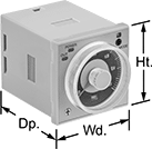 |
Install these relays in a panel cutout or plug them into a relay socket. Unlike mechanical relays, these solid state relays have no moving parts, so they require less maintenance and last longer, are quieter, and switch faster. They give you a variety of timing functions in one relay.
Sockets—Relay sockets (sold separately) mount to 35 mm DIN rail (also known as DIN 3 rail) for fast installation. They also mount to flat surfaces.
Timer Relays | Sockets | |||||||||||||||
|---|---|---|---|---|---|---|---|---|---|---|---|---|---|---|---|---|
Timing Range | ||||||||||||||||
No. of Terminals | Input Voltage | Control Current, mA | Timer Relay Function | No. of | Overall | Switching Current @ Voltage | Ht. | Wd. | Dp. | Features | Each | Each | ||||
2 Circuits Controlled with 2 Off or 2 On—DPDT | ||||||||||||||||
| 8 | 120V AC, 240V AC, 110V DC, 120V DC | 13 | Delayed Start (Delay on Make) Interval Switch on (Single Shot) Repeat Cycle | 4 | 0.05 sec. to 300 hr. | 5 amp @ 240V AC | 1.9" | 1.9" | 2.3" | Indicator Light | 69695K51 | 0000000 | 7122K19 | 00000 | ||
Two-Hand Push-Button Safety Switches
 |
It takes two hands to activate these switches, minimizing the risk of accidental equipment start-up. They have an emergency stop push-button to immediately cut power. They’re rated IP65 for protection from low-pressure washdowns.
Switches with push-button actuators require a safety relay (sold separately) for a complete system.
Actuator | Mounting | |||||||||||||||
|---|---|---|---|---|---|---|---|---|---|---|---|---|---|---|---|---|
No. of Circuits Controlled | Switch Starting Position | Switch Action | Switch Designation | Material | Color | Switching Current @ Voltage | Ht. | Wd. | Dp. | No. of Holes | Hole Dia. | Fasteners Included | Features | Each | ||
| 2 | 1 Off and 1 On | Momentary | DPST-1NO/1NC | Plastic | Black | 8 amp @ 250V AC, 5 amp @ 24V DC | 7 5/16" | 18 1/2" | 5 7/16" | 2 | 29/64" | No | Emergency Stop Button | 65945K71 | 0000000 | |
 |
Input Voltage, V DC | No. of Terminals | Switching Current @ Voltage | For DIN Rail Ht., mm | Wire Connection | Features | Each | |||
|---|---|---|---|---|---|---|---|---|---|
2 Circuits Controlled with 1 Off and 1 On Switch Starting Position—DPST-1NO/1NC | |||||||||
| 24 | 12 | 5.5 amp @ 24V DC | 35 | Screw Terminal | Self-Monitoring Circuitry | 65945K72 | 0000000 | ||
Safety Relays
SIL 3, PLe Max. System Safety Rating—DIN-Rail Mount
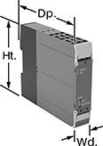 |
Relays that meet SIL 3 are tested for applications with a probability of failure of 0.01% to 0.1% and are used for preventing fires, explosions, or toxic releases.
Mirror Auxiliary Contacts—Relays with mirror auxiliary contacts have contacts that are normally closed and cannot be open at the same time as a normally open main contact.
Nondetachable Auxiliary Contacts—Relays with nondetachable contacts have auxiliary contacts that won’t separate from the relay if there is shock or vibration.
Self-Monitoring Circuitry—When a failure is detected, relays with self-monitoring circuitry signal the controller to remove power and prevent restarting until the issue is resolved.
No. of Terminals | Input Voltage | Control Current, mA | Switching Current @ Voltage | Max. Switching Voltage, V AC | Aux. Contact Switch Starting Position | Ht. | Wd. | Dp. | Features | Each | |||
|---|---|---|---|---|---|---|---|---|---|---|---|---|---|
Spring-Clamp-Terminal Wire Connection | |||||||||||||
3 Circuits Controlled with 3 Off—3PST-NO | |||||||||||||
| 18 | 24V AC, 24V DC | 5 | 5 amp @ 120V AC | 230 | 1 On | 3.9" | 0.9" | 4.8" | Interlocked Opposing Contacts, LED Indicator, Mirror Auxiliary Contacts, Nondetachable Auxiliary Contacts, Recessed Terminals, Self-Monitoring Circuitry | 6242N122 | 0000000 | ||
Current-Monitoring Relays
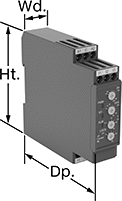 |
Screw Terminals Knob Adjustment |
Protect electrical equipment from overcurrent and undercurrent damage—these relays continuously monitor current flow. When current is outside a set range, they trip and cut power to prevent overheating, fire hazards, and stalling. Rated IP20, these relays have recessed terminals that keep fingers and other objects from touching live circuits. Mount them on a 35 mm DIN rail (also known as DIN 3 rail) for fast installation.
Knob Adjustment—Relays with knob adjustments have knobs right on the front where you can set your trip current. You can see that they're wired correctly and when they're actuated based on the LED indicators.
No. of Terminals | Input Voltage | Trip Current Setting, amp | Trip Time, sec. | Reset Type | Switching Current @ Voltage | Max. Switching Voltage | Adjustment Mechanism | Ht. | Wd. | Dp. | Each | |||
|---|---|---|---|---|---|---|---|---|---|---|---|---|---|---|
Screw Terminals | ||||||||||||||
1 Circuit Controlled with 1 Off or 1 On—SPDT | ||||||||||||||
| 9 | 24V AC, 24V DC | 0.1 to 1, 0.5 to 5, 0.8 to 8 | 0.1 to 30 | Automatic, Manual | 5 amp @ 240V AC 5 amp @ 30V DC | 250V AC 30V DC | Knob | 3.5" | 0.9" | 3.9" | 8123N14 | 0000000 | ||
| 9 | 120V AC, 240V AC | 0.1 to 1, 0.5 to 5, 0.8 to 8 | 0.1 to 30 | Automatic, Manual | 5 amp @ 240V AC 5 amp @ 30V DC | 250V AC 30V DC | Knob | 3.5" | 0.9" | 3.9" | 8123N13 | 000000 | ||
Voltage-Monitoring Relays
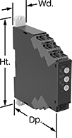 |
Safeguard your equipment against overheating, wear, and malfunction from a spike or dip in voltage. These relays continuously monitor your AC or DC power supply and trip when the voltage is outside a set range. Rated IP20, these relays have recessed terminals that keep fingers and other objects from touching live circuits. Mount them on a 35 mm DIN rail (also known as DIN 3 rail) for fast installation.
With Spring-Clamp Terminals—Relays with spring-clamp terminals connect and disconnect to wire without screws. Because there’s no screw, these connections are less likely to loosen over time, even in high-vibration environments.
Knob Adjustment—Relays with knob adjustments have knobs right on the front where you can set your trip voltage. You can see that they're wired correctly and when they're actuated based on the LED indicators. If you want to mount these relays to a surface instead of DIN rail, they have mounting holes.
No. of Terminals | Input Voltage | Trip Voltage Setting | Trip Time, sec. | Reset Type | Switching Current @ Voltage | Max. Switching Voltage | Adjustment Mechanism | Ht. | Wd. | Dp. | Features | Each | |||
|---|---|---|---|---|---|---|---|---|---|---|---|---|---|---|---|
1 Circuit Controlled with 1 Off or 1 On—SPDT | |||||||||||||||
With Spring-Clamp Terminals | |||||||||||||||
| 9 | 24V AC, 24V DC | 1V AC to 10V AC 3V AC to 30V AC 15V AC to 150V AC 1V DC to 10V DC 3V DC to 30V DC 15V DC to 150V DC | 0.1 to 30 | Automatic, Manual | 5 amp @ 240V AC 5 amp @ 30V DC | 250V AC 48V DC | Knob | 3.5" | 0.7" | 3.5" | LED Indicator | 8446N101 | 0000000 | ||
| 9 | 24V AC, 24V DC | 20V AC to 200V AC 30V AC to 300V AC 60V AC to 600V AC 20V DC to 200V DC 30V DC to 300V DC 60V DC to 600V DC | 0.1 to 30 | Automatic, Manual | 5 amp @ 240V AC 5 amp @ 30V DC | 250V AC 48V DC | Knob | 3.5" | 0.7" | 3.5" | LED Indicator | 8446N103 | 000000 | ||
| 9 | 120V AC, 240V AC | 1V AC to 10V AC 3V AC to 30V AC 15V AC to 150V AC 1V DC to 10V DC 3V DC to 30V DC 15V DC to 150V DC | 0.1 to 30 | Automatic, Manual | 5 amp @ 240V AC 5 amp @ 30V DC | 250V AC 48V DC | Knob | 3.5" | 0.7" | 3.5" | LED Indicator | 8446N102 | 000000 | ||
| 9 | 120V AC, 240V AC | 20V AC to 200V AC 30V AC to 300V AC 60V AC to 600V AC 20V DC to 200V DC 30V DC to 300V DC 60V DC to 600V DC | 0.1 to 30 | Automatic, Manual | 5 amp @ 240V AC 5 amp @ 30V DC | 250V AC 48V DC | Knob | 3.5" | 0.7" | 3.5" | LED Indicator | 8446N104 | 000000 | ||
DIN-Rail Mount Solid State Interface Relays
1 Circuit Controlled with 1 Off—SPST-NO
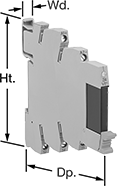 |
With Screw Terminals |
Interface Relays | Replacement Relays | |||||||||||||
|---|---|---|---|---|---|---|---|---|---|---|---|---|---|---|
No. of Terminals | Input Voltage | Control Current, mA | Switching Current @ Voltage | Max. Switching Voltage, V DC | Ht. | Wd. | Dp. | Features | Each | Each | ||||
With Screw Terminals | ||||||||||||||
| 5 | 24V AC, 48V AC, 120V AC, 240V AC, 24V DC, 48V DC, 60V DC, 120V DC, 240V DC | 18 | 5 amp @ 30V DC | 33 | 3.5" | 0.5" | 3.4" | LED Power Indicator | 8299K15 | 000000 | 4026N16 | 000000 | ||
Ground-Fault Monitoring Relays
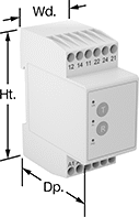 | 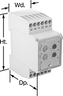 |
Screw Terminals | Screw Terminals Knob Adjustment |
Detect and mitigate ground faults to prevent harm to equipment, circuits, and people. These relays monitor the differential between incoming and outgoing current, also known as residual current. When the balance is off, they trip and cut power to the circuit. These relays are highly sensitive, so you can trust them to de-energize faulty circuits before a minor issue becomes a major one. Rated IP20, they have recessed terminals that keep fingers and other objects from touching live circuits. Mount them on 35 mm DIN rail (also known as DIN 3 rail) for fast installation.
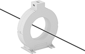
These relays require a current-indicating ring (sold separately) to operate. Choose a ring that is large enough for your lines to pass through. Feed the lines of the circuit through the center of the ring and connect the indicating ring output to the relay.
Knob Adjustment—Relays with knob adjustments have knobs right on the front where you can set your trip current.
LED Indicator—Relays with an LED indicator show the status of your relay, so you know it is wired correctly and when it is actuated.
No. of Terminals | Input Voltage, V AC | Trip Current Setting, amp | Trip Current, amp | Trip Time, sec. | Switching Current @ Voltage | Max. Switching Voltage | Adjustment Mechanism | Ht. | Wd. | Dp. | Features | Each | |||
|---|---|---|---|---|---|---|---|---|---|---|---|---|---|---|---|
Screw Terminals | |||||||||||||||
2 Circuits Controlled with 2 Off or 2 On—DPDT | |||||||||||||||
| 12 | 24, 48, 120, 240 | 0.03 | — | 0 | 5 amp @ 240V AC 5 amp @ 24V DC | 250V AC 24V DC | — | 3.2" | 1.4" | 2.6" | LED Indicator | 8121N101 | 0000000 | ||
| 12 | 24, 48, 120, 240 | 0.3 | — | 0 | 5 amp @ 240V AC 5 amp @ 24V DC | 250V AC 24V DC | — | 3.2" | 1.4" | 2.6" | LED Indicator | 8121N102 | 000000 | ||
| 12 | 24, 48, 120, 240 | — | 0.03 to 5 | 0 to 5 | 5 amp @ 240V AC 5 amp @ 24V DC | 250V AC 24V DC | Knob | 3.2" | 1.4" | 2.8" | LED Indicator | 8121N103 | 000000 | ||
| 12 | 24, 48, 120, 240 | — | 0.3 to 30 | 0 to 5 | 5 amp @ 240V AC 5 amp @ 24V DC | 250V AC 24V DC | Knob | 3.2" | 1.4" | 2.8" | LED Indicator | 8121N104 | 000000 | ||
Frequency-Monitoring Relays
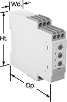 |  |
DIN-Rail Mount | Relay-Socket Mount |
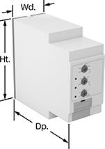
Prevent changes in frequency from damaging sensitive equipment. Often used with motors, fluorescent lighting, and controllers, these relays cut power to your device if the frequency falls outside the set range. Switches on the front of these relays let you set your trip frequency and time. You can see that they're wired correctly and when they're actuated based on the LED indicators. Rated IP20, these relays have recessed terminals that keep fingers and other objects from touching live circuits.
DIN-Rail Mount—DIN-rail mount relays snap onto 35 mm DIN rail (also known as DIN 3 rail) for fast installation.
Relay-Socket Mount—Relay-socket mount relays plug into a socket (sold separately), which is required for installation.
Monitoring Relays | Sockets | |||||||||||||||||
|---|---|---|---|---|---|---|---|---|---|---|---|---|---|---|---|---|---|---|
Trip Frequency Setting, Hz | ||||||||||||||||||
No. of Terminals | Input Voltage, V AC | 50 Hz Input | 60 Hz Input | Trip Time, sec. | Reset Type | Switching Current @ Voltage | Max. Switching Voltage | Adjustment Mechanism | Ht. | Wd. | Dp. | Features | Each | Each | ||||
1 Circuit Controlled with 1 Off or 1 On—SPDT | ||||||||||||||||||
DIN-Rail Mount | ||||||||||||||||||
| 9 | 24, 48, 120, 240 | 40 to 60 48 to 52 | 50 to 70 58 to 62 | 0.1 to 30 | Automatic, Manual | 8 amp @ 240V AC 5 amp @ 24V DC | 250V AC 24V DC | DIP Switch | 3.1" | 0.9" | 3.9" | LED Indicator | 8477N11 | 0000000 | ——— | 0 | ||
Relay-Socket Mount | ||||||||||||||||||
| 1 | 24, 48, 120, 240 | 40 to 60 48 to 52 | 50 to 70 58 to 62 | 0.1 to 30 | Automatic, Manual | 8 amp @ 240V AC 5 amp @ 24V DC | 250V AC 24V DC | DIP Switch | 3.1" | 1.4" | 3.7" | LED Indicator | 8477N12 | 000000 | 7122K12 | 000000 | ||
DIN-Rail Mount Motor Voltage Monitors
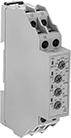 |
Mount these monitors to 35 mm DIN rail. They protect electric motors from phase loss, phase reversal, overvoltage, undervoltage, and voltage imbalance. Also known as voltage-monitoring relays, they cut power to a motor when a fault occurs.
For the Manufacturer User Manual, click on a part number and select Product Detail.
Switching | ||||||||||||||
|---|---|---|---|---|---|---|---|---|---|---|---|---|---|---|
Input Voltage Range, V AC | No. of Terminals | Control Power, W | Voltage Imbalance Adjustment | Trip Time, sec. | Reset Type | Current, amp | Voltage, V AC | Ht. | Wd. | Certification | Each | |||
1 Circuit Controlled with 1 Off or 1 On—SPDT | ||||||||||||||
For Three Phase | ||||||||||||||
| 208 to 480 | 6 | 3 | 10% | 0.5 to 100 | Automatic | 5 | 240 | 3.5" | 0.71" | UL Listed, C-UL Listed, CE Marked | 6969K71 | 0000000 | ||
