


Filter by
Switching Current
Horsepower @ Switching Voltage
Switching Voltage
Operation Type
Certification
Wire Connection

Switch Action
Mechanical Life Cycles
Electrical Connection
U.S.–Mexico–Canada Agreement (USMCA) Qualifying
DFARS Specialty Metals
Export Control Classification Number (ECCN)
DIN-Rail Mount Touch-Safe Screw Terminal Relays
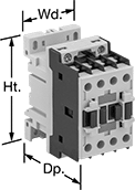 |
Quickly and safely mount these relays on 35 mm DIN rail (also known as DIN 3). IP20 rated, they have recessed terminals that prevent fingers and other objects from touching live circuits.
4 Circuits Controlled—Relays that control 3 and 4 circuits are built to IEC dimensional standards and are often called IEC contactors.
12 Terminals—Relays with 12 terminals let you attach the control circuit onto the side that works best for your setup, which reduces the amount of wire you need.
hp @ Switching Voltage | |||||||||||||
|---|---|---|---|---|---|---|---|---|---|---|---|---|---|
No. of Terminals | Input Voltage | Control Power | Switching Current @ Voltage (Load Type) | Max. Switching Voltage, V AC | Single Phase | Three Phase | Ht. | Wd. | Dp. | Each | |||
4 Circuits Controlled with 4 Off—4PST-NO | |||||||||||||
| 12 | 24V AC | 6.5 VA | 9 amp @ 600V AC (Full) 25 amp @ 600V AC (Resistive) | 600 | 3/4 hp @ 120V AC 2 hp @ 240V AC | 3 hp @ 240V AC 5 hp @ 480V AC 7 1/2 hp @ 600V AC | 3.2" | 1.8" | 3.2" | 70255K651 | 000000 | ||
| 12 | 120V AC | 6.5 VA | 9 amp @ 600V AC (Full) 25 amp @ 600V AC (Resistive) | 600 | 3/4 hp @ 120V AC 2 hp @ 240V AC | 3 hp @ 240V AC 5 hp @ 480V AC 7 1/2 hp @ 600V AC | 3.2" | 1.8" | 3.2" | 70255K652 | 00000 | ||
| 12 | 240V AC | 6.5 VA | 9 amp @ 600V AC (Full) 25 amp @ 600V AC (Resistive) | 600 | 3/4 hp @ 120V AC 2 hp @ 240V AC | 3 hp @ 240V AC 5 hp @ 480V AC 7 1/2 hp @ 600V AC | 3.2" | 1.8" | 3.2" | 70255K653 | 00000 | ||
| 12 | 24V DC | 5.4 W | 9 amp @ 600V AC (Full) 25 amp @ 600V AC (Resistive) | 600 | 3/4 hp @ 120V AC 2 hp @ 240V AC | 3 hp @ 240V AC 5 hp @ 480V AC 7 1/2 hp @ 600V AC | 3.2" | 1.8" | 3.9" | 70255K28 | 000000 | ||
 |
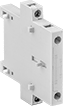
Front Mount |
No. of Circuits Controlled | For Relay Wd. | Switch Starting Position | Switch Designation | Mounting Location | Each | ||
|---|---|---|---|---|---|---|---|
| 2 | 1.8", 2.2", 2.4" | 2 Off | DPST-NO | Front | 8728N12 | 000000 | |
| 2 | 1.8", 2.2", 2.4" | 2 On | DPST-NC | Front | 8728N11 | 00000 | |
| 4 | 1.8", 2.2", 2.4" | 1 Off and 3 On | 4PST-1NO/3NC | Front | 8728N15 | 00000 | |
| 4 | 1.8", 2.2", 2.4" | 2 Off and 2 On | 4PST-2NO/2NC | Front | 8728N16 | 00000 | |
| 4 | 1.8", 2.2", 2.4" | 3 Off and 1 On | 4PST-3NO/1NC | Front | 8728N17 | 00000 | |
| 4 | 1.8", 2.2", 2.4" | 4 Off | 4PST-NO | Front | 8728N14 | 00000 | |
| 4 | 1.8", 2.2", 2.4" | 4 On | 4PST-NC | Front | 8728N13 | 00000 |
Safety Relays
SIL 3, PLe, CAT IV, 600V Max. System Safety Rating—DIN-Rail and Surface Mount
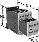 |
Relays that meet SIL 3 are tested for applications with a probability of failure of 0.01% to 0.1% and are used for preventing fires, explosions, or toxic releases.
Relays that meet CAT 4 withstand circuit surges in electrical applications up to 600V.
Mirror Auxiliary Contacts—Relays with mirror auxiliary contacts have contacts that are normally closed and cannot be open at the same time as a normally open main contact.
Nondetachable Auxiliary Contacts—Relays with nondetachable contacts have auxiliary contacts that won’t separate from the relay if there is shock or vibration.
Self-Monitoring Circuitry—When a failure is detected, relays with self-monitoring circuitry signal the controller to remove power and prevent restarting until the issue is resolved.
hp @ Switching Voltage | |||||||||||||||
|---|---|---|---|---|---|---|---|---|---|---|---|---|---|---|---|
No. of Terminals | Input Voltage | Control Current, mA | Switching Current @ Voltage | Max. Switching Voltage, V AC | Single Phase | Three Phase | Aux. Contact Switch Starting Position | Ht. | Wd. | Dp. | Features | Each | |||
Screw-Terminal Wire Connection | |||||||||||||||
3 Circuits Controlled with 3 Off—3PST-NO | |||||||||||||||
| 18 | 120V AC | 2 | 9 amp @ 400V AC | 600 | 1/2 hp @ 120V AC 1 1/2 hp @ 240V AC | 3 hp @ 240V AC 5 hp @ 480V AC 7 1/2 hp @ 600V AC | 2 Off and 3 On | 2.7" | 1.8" | 4.6" | Inspection Window, Interlocked Opposing Contacts, Mirror Auxiliary Contacts, Nondetachable Auxiliary Contacts, Recessed Terminals, Self-Monitoring Circuitry | 6242N12 | 0000000 | ||
| 18 | 24V DC | 18 | 9 amp @ 400V AC | 600 | 1/2 hp @ 120V AC 1 1/2 hp @ 240V AC | 3 hp @ 240V AC 5 hp @ 480V AC 7 1/2 hp @ 600V AC | 2 Off and 3 On | 2.7" | 1.8" | 4.6" | Inspection Window, Interlocked Opposing Contacts, Mirror Auxiliary Contacts, Nondetachable Auxiliary Contacts, Recessed Terminals, Self-Monitoring Circuitry | 6242N16 | 000000 | ||
Energy-Saving Motor Starters
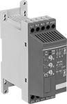 |
Save electricity and extend motor life by reducing the motor's starting current. These starters gradually start and stop motors. Use them on motors where torque varies, such as pumps, compressors, and conveyors. All have an auxiliary contact to send a signal or connect to another device, such as an alarm or indicating light.
Switching | Time, sec. | ||||||||||||||
|---|---|---|---|---|---|---|---|---|---|---|---|---|---|---|---|
Full Load Current, amp | Input Voltage, V DC | Voltage, V AC | Current, amp | Electrical Phase | Accel. | Deceleration | Ht. | Wd. | Mounting Location | For DIN Rail Ht., mm | Certification | Each | |||
Motor Starters with 1 Auxiliary Contact—1 Off | |||||||||||||||
| 9 | 24 | 208 to 600 | 9 | Three (2 hp @ 240V AC) Three (5 hp @ 480V AC) | 1 to 20 | 0 to 20 | 5.5" | 1.8" | DIN Rail, Surface | 35 | UL Listed, C-UL Listed, CE Marked | 7112T42 | 0000000 | ||
