Wireless Enclosed Relays
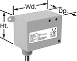
Send a signal to turn equipment on and off from up to 150 feet away without having to run electrical wire. These relays have an enclosure to protect the terminals from dust and accidental bumps. They can be set to transmit, receive, or both at once. You’ll need at least two relays to switch a device. They have an alarm that can be set to check for certain conditions before transmitting a signal. For example, you could set these relays to send a signal to turn on an air conditioner if all windows are closed. The repeat function extends the transmitting signal through a maximum of two receiving relays.
Relays that are set to transmit can be linked up to as many receiving relays as you need. Relays set to receive can be linked up to 30 transmitting relays. All relays connect to dry contacts on your switch, sensor, or controller. Use the wire leads to connect them to a power source.
UL and C-UL listed, all meet American and Canadian safety standards. Rated NEMA 1, they should only be used indoors.
Wire Lead | Conduit Connection | |||||||||||||||
|---|---|---|---|---|---|---|---|---|---|---|---|---|---|---|---|---|
| Input Voltage | Control Current | Switching Current @ 277V AC | Maximum Switching Voltage | hp @ Switching Voltage | Ht. | Wd. | Dp. | Maximum Transmission Distance, ft. | Lg. | Number of | Gender | Trade Size | Thread Type | Environmental Rating | Each | |
1 Circuit Controlled with 1 Off (Normally Open) or 1 On (Normally Closed)—SPDT | ||||||||||||||||
| 120V AC | 73 | 20A | 277V AC | 2 hp @ 277 V AC | 2.3" | 3.2" | 1.8" | 150 | 16" | 7 | Male | 1/2 | NPT | NEMA 1 | 0000000 | 0000000 |
| 208V AC | 80 | 20A | 277V AC | 2 hp @ 277 V AC | 2.3" | 3.2" | 1.8" | 150 | 16" | 7 | Male | 1/2 | NPT | NEMA 1 | 0000000 | 000000 |
| 240V AC | 80 | 20A | 277V AC | 2 hp @ 277 V AC | 2.3" | 3.2" | 1.8" | 150 | 16" | 7 | Male | 1/2 | NPT | NEMA 1 | 0000000 | 000000 |
| 277V AC | 80 | 20A | 277V AC | 2 hp @ 277 V AC | 2.3" | 3.2" | 1.8" | 150 | 16" | 7 | Male | 1/2 | NPT | NEMA 1 | 0000000 | 000000 |
| 24V AC, 24V DC | 69 | 20A | 277V AC | 2 hp @ 277 V AC | 2.3" | 3.2" | 1.8" | 150 | 16" | 7 | Male | 1/2 | NPT | NEMA 1 | 0000000 | 000000 |
Network-Enabled Relays


With a built-in web server, these relays can be remotely controlled over any IP network, including the Internet. They connect to your network either wirelessly or with an Ethernet cable (not included). No programming or software is required to operate these relays. Instead, use your web browser to input the relay’s IP address and the website guides you through simple menus and drop-down lists to set your parameters. Alternatively, you can use these relays with a PLC or without a computer at all if you use one relay as a controller for another relay.
Each circuit has a digital input that can be used to control the relay or a remote relay over the IP network. You could also use the digital input to monitor a separate device, such as a push-button or door alarm switch. These relays can be set to automatically restart network devices, such as computers, even when they fail to respond to relay signals. LED indicators let you know if there’s input and output voltage and if the network is connected and active. All meet at least one safety standard.
Mount these relays on 35 mm DIN rail (also known as DIN 3 rail) for fast installation. They also mount to flat surfaces.
Relays that control 2 circuits can also be programmed from a downloadable app or programs written in BASIC script, making them easy to customize. The website logs and stores data and device information.
Power over Ethernet (PoE) compatible relays can receive power from PoE cables (not included).
Digital Inputs | Digital Outputs | ||||||||||||||||
|---|---|---|---|---|---|---|---|---|---|---|---|---|---|---|---|---|---|
| Number of Terminals | Voltage | No. of | Voltage | No. of | Control Current, A | Switching Current @ Voltage | Max. Switching Voltage | Ht. | Wd. | Dp. | Connection Type | Power Over Ethernet Standard | Communication Protocol | Operating System Compatibility | Features | Each | |
1 Circuit Controlled with 1 Off (Normally Open) or 1 On (Normally Closed)—SPDT | |||||||||||||||||
| 8 | 6V DC, 9V DC, 12V DC, 24V DC | 1 | 5V DC | 1 | 12 | 12 A @ 30 V DC | 30V DC | 3.9" | 1.4" | 3.1" | Ethernet | __ | Modbus TCP/IP | Android 6.0 or Later, iOS 9 or Later, Windows XP or Later | LED Indicators | 0000000 | 0000000 |
| 8 | 6V DC, 9V DC, 12V DC, 24V DC | 1 | 5V DC | 1 | 12 | 12 A @ 30 V DC | 30V DC | 3.9" | 1.4" | 3.1" | Ethernet | PoE, Type 1 | Modbus TCP/IP | Android 6.0 or Later, iOS 9 or Later, Windows XP or Later | LED Indicators | 0000000 | 000000 |
2 Circuits Controlled with 1 Off (Normally Open) or 1 On (Normally Closed)—SPDT | |||||||||||||||||
| 14 | 4V DC, 6V DC, 12V DC, 24V DC | 2 | 3V DC, 5V DC, 11V DC, 23V DC | 2 | 3 | 3 A @ 24 V DC | 24V DC | 3.9" | 1.4" | 3.1" | Ethernet | __ | Modbus TCP/IP, SMTP | Android 6.0 or Later, iOS 9 or Later, Windows XP or Later | LED Indicators, Data Logging Capabilities | 0000000 | 000000 |
| 14 | 4V DC, 6V DC, 12V DC, 24V DC | 2 | 11V DC | 2 | 3 | 3 A @ 24 V DC | 24V DC | 3.9" | 1.4" | 3.1" | Ethernet | PoE, Type 1 | Modbus TCP/IP, SMTP | Android 6.0 or Later, iOS 9 or Later, Windows XP or Later | LED Indicators, Data Logging Capabilities | 0000000 | 000000 |
Ground-Fault Monitoring Relays
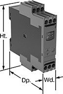
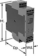
Detect and mitigate ground faults to prevent harm to equipment, circuits, and people. These relays monitor the differential between incoming and outgoing current, also known as residual current. When the balance is off, they trip and cut power to the circuit. These relays are highly sensitive, so you can trust them to de-energize faulty circuits before a minor issue becomes a major one. Rated IP20, they have recessed terminals that keep fingers and other objects from touching live circuits. Mount them on 35 mm DIN rail (also known as DIN 3 rail) for fast installation.
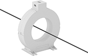
These relays require a current-indicating ring (sold separately) to operate. Choose a ring that is large enough for your lines to pass through. Feed the lines of the circuit through the center of the ring and connect the indicating ring output to the relay.
Relays with spring-clamp terminals connect and disconnect to wire without screws. Because they don’t have screws, there’s less of a risk that they will loosen over time, even when they’re under vibration.
Relays with IO link can be programmed, monitored, and reset remotely by connecting them to a programmable logic controller (PLC), human-machine interface (HMI), or computer. If you want to program them locally, they have a keypad.
Trip Current | |||||||||||||
|---|---|---|---|---|---|---|---|---|---|---|---|---|---|
| No. of Terminals | Input Voltage | Min. | Max. | Trip Time, sec. | Switching Current @ Voltage | Max. Switching Voltage | Adjustment Style | Ht. | Wd. | Dp. | Features | Each | |
Screw Terminals with IO Link | |||||||||||||
2 Off (Normally Open) or 2 On (Normally Closed)—DPDT | |||||||||||||
| 12 | 24V DC | 0.03A | 40A | 0-999 | 3 A @ 240 V AC 1 A @ 24 V DC | 400V AC 250V DC | Keypad, External Controller | 4" | 0.9" | 3.6" | Remote Reset | 00000000 | 0000000 |
Spring-Clamp Terminals with IO Link | |||||||||||||
2 Off (Normally Open) or 2 On (Normally Closed)—DPDT | |||||||||||||
| 12 | 24V DC | 0.03A | 40A | 0-999 | 3 A @ 240 V AC 1 A @ 24 V DC | 400V AC 250V DC | Keypad, External Controller | 4.1" | 0.9" | 3.6" | Remote Reset | 00000000 | 000000 |
Voltage-Monitoring Relays
Safeguard your equipment against overheating, wear, and malfunction from a spike or dip in voltage. These relays continuously monitor your AC or DC power supply and trip when the voltage is outside a set range. Rated IP20, these relays have recessed terminals that keep fingers and other objects from touching live circuits. Mount them on a 35 mm DIN rail (also known as DIN 3 rail) for fast installation.
Relays with IO link can be programmed, monitored and reset remotely by connecting them to a programmable logic controller (PLC), human-machine interface (HMI), or computer. If you want to program them locally, they have a keypad.
Relays with spring-clamp terminals connect and disconnect to wire without screws. Because there’s no screw, these connections are less likely to loosen over time, even in high-vibration environments.
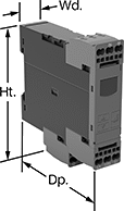
Trip Voltage | |||||||||||||||
|---|---|---|---|---|---|---|---|---|---|---|---|---|---|---|---|
| Number of Terminals | Input Voltage | Min. | Max. | Trip Time, sec. | Reset Type | Switching Current @ Voltage | Max. Switching Voltage | Adjustment Style | Ht. | Wd. | Dp. | Display Type | Features | Each | |
1 Circuit Controlled with 1 Off (Normally Open) or 1 On (Normally Closed)—SPDT | |||||||||||||||
With Screw Terminals | |||||||||||||||
| 9 | 24V DC | 10V AC/DC | 600V AC/DC | 0-999 | Automatic | 3 A @ 240 V AC 1 A @ 24 V DC | 400V AC 250V DC | Keypad, External Controller | 3.6" | 0.9" | 3.6" | LCD | Remote Reset | 00000000 | 0000000 |
With Spring-Clamp Terminals | |||||||||||||||
| 9 | 24V DC | 10V AC/DC | 600V AC/DC | 0-999 | Automatic | 3 A @ 240 V AC 1 A @ 24 V DC | 400V AC 250V DC | Keypad, External Controller | 3.8" | 0.9" | 3.6" | LCD | Remote Reset | 00000000 | 000000 |
Multifunction Monitoring Relays

Monitor phase, voltage, and frequency at the same time to protect motors, generators, and other three-phase circuits from burning out or overheating. They'll switch the circuit off if they detect voltage or frequencies outside of the set range or phase loss, imbalance, or reversal. Rated IP20, they have recessed terminals that keep fingers and other objects from touching live circuits. Mount them on a 35 mm DIN (also known as DIN 3 rail) for fast installation.
These relays use IO Link, so they can be programmed, monitored, and reset remotely by connecting them to a programmable logic controller (PLC), human-machine interface (HMI), or computer. If you want to program them locally, they have a keypad.
Relays with spring-clamp terminals connect and disconnect to wire without screws. Because there’s no screw, these connections are less likely to loosen over time, even in high-vibration environments.
Trip Voltage | Trip Frequency | |||||||||||||||
|---|---|---|---|---|---|---|---|---|---|---|---|---|---|---|---|---|
| Number of Terminals | Input Voltage | Min. | Max. | Input Frequency, Hz | Min., Hz | Max., Hz | Trip Time, sec. | Reset Type | Switching Current @ Voltage | Max. Switching Voltage | Adjustment Style | Ht. | Wd. | Dp. | Each | |
1 Circuit Controlled with 1 Off (Normally Open) or 1 On (Normally Closed)—SPDT | ||||||||||||||||
With Screw Terminals and IO Link | ||||||||||||||||
| 12 | 24V DC | 90V AC | 760V AC | 50, 60 | 15 | 70 | 0.1-30 | Automatic | 3 A @ 240 V AC 1 A @ 24 V DC | 400V AC 250V DC | Keypad, External Controller | 3.9" | 0.9" | 3.6" | 0000000 | 0000000 |
With Spring-Clamp Terminals and IO Link | ||||||||||||||||
| 12 | 24V DC | 90V AC | 760V AC | 50, 60 | 15 | 70 | 0.1-30 | Automatic | 3 A @ 240 V AC 1 A @ 24 V DC | 400V AC 250V DC | Keypad, External Controller | 3.9" | 0.9" | 3.6" | 0000000 | 000000 |
Current-Monitoring Relays
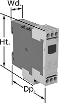
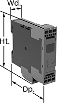
Protect electrical equipment from overcurrent and undercurrent damage—these relays continuously monitor current flow. When current is outside a set range, they trip and cut power to prevent overheating, fire hazards, and stalling. Rated IP20, these relays have recessed terminals that keep fingers and other objects from touching live circuits. Mount them on a 35 mm DIN rail (also known as DIN 3 rail) for fast installation.
Relays with spring-clamp terminals connect and disconnect to wire without screws. Because there’s no screw, these connections are less likely to loosen over time, even in high-vibration environments.
Relays with IO link can be programmed, monitored, and reset remotely by connecting them to a programmable logic controller (PLC), human-machine interface (HMI), or computer. If you want to program them locally, they have a keypad.
Trip Current | ||||||||||||||
|---|---|---|---|---|---|---|---|---|---|---|---|---|---|---|
| No. of Terminals | Input Voltage | Min. | Max. | Trip Time, sec. | Reset Type | Switching Current @ Voltage | Max. Switching Voltage | Adjustment Style | Ht. | Wd. | Dp. | Display Type | Each | |
Screw Terminals with IO Link | ||||||||||||||
1 Off (Normally Open) or 1 On (Normally Closed)—SPDT | ||||||||||||||
| 9 | 24V DC | 0.05A | 10A | 0-999 | Automatic | 1 A @ 24 V DC 3 A @ 240 V AC | 400V AC 250V DC | External Controller, Keypad | 3.6" | 0.9" | 3.4" | LCD | 0000000 | 0000000 |
Spring-Clamp Terminals with IO Link | ||||||||||||||
1 Off (Normally Open) or 1 On (Normally Closed)—SPDT | ||||||||||||||
| 9 | 24V DC | 0.05A | 10A | 0-999 | Automatic | 1 A @ 24 V DC 3 A @ 240 V AC | 400V AC 250V DC | External Controller, Keypad | 3.8" | 0.9" | 3.4" | LCD | 0000000 | 000000 |


