Choosing a Proximity Switch
More
About Timing Functions
More
About Timer Relays
More
DIN-Rail Mount Multifunction Timer Relays


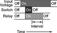
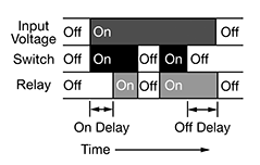


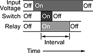

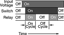
Control multiple timing functions from your electrical cabinet—these timer relays mount to 35 mm DIN rail (also known as DIN 3 rail), which is the most commonly used size. UL Listed, C-UL Listed, and CE Marked, these relays meet American, Canadian, and European safety standards.
Timer Relays with Delayed, Interval, Switch-On, and Repeat Cycles
With six different functions, these timer relays have a broad range of applications. Use them to precisely control machines such as conveyors, lighting systems, and electric motors.
The delayed start (delay-on-make) function allows you to set how long it takes for the relay to turn on after input voltage is applied. For example, a drill starts pumping lubricant immediately, but it does not start rotating until the set time has elapsed.
The delayed switch-on with delayed switch-off function uses a switch instead of input voltage. It allows you to set how long it takes the relay to turn on after a switch is turned on, and how long it will stay on after the switch is turned off. For example, a furnace turns on, but the fan doesn’t start pushing air through the vents until it has been heated. When the furnace turns off, the fan keeps blowing to circulate all the hot air.
The delayed switch-off (delay-on-break) function uses a switch instead of input voltage. When the switch is turned off, the relay remains on for a programmed amount of time before turning off. For example, a projector’s light is turned off with a switch, but its cooling fan continues to run for a set time.
The interval function uses input voltage to turn on the relay for a programmed amount of time. For example, when a part moving down a conveyor reaches a certain location, a cleaning spray comes on for a set time.
The switch-on (single-shot) function requires a switch to activate the relay, which stays on for the programmed amount of time. For example, lights in a storage room are turned on with a switch and stay on for a set time before turning off.
The repeat cycle function alternates between an on cycle and off cycle of equal durations until input voltage is removed. A common example would be a flashing light.
Timer Relays with Asymmetrical Repeat Cycles
Use these timer relays when your repeat cycles have different on- and off-cycle durations.
The asymmetrical repeat cycle alternates between different durations of on and off for as long as input voltage is applied. For example, a sprinkler system sprays in short bursts followed by longer rest periods, on and off until input voltage is removed.
The switch-on asymmetrical repeat cycle function is activated with a switch instead of input voltage. It could be used to turn on an electric motor for a short period and then turn it off for a longer rest period, repeating that pattern until the switch is turned off.
Timing Range | ||||||||||||
|---|---|---|---|---|---|---|---|---|---|---|---|---|
| No. of Terminals | Input Voltage | Control Current, mA | Timer Relay Function | No. of | Overall | Switching Current @ 240V AC | Max. Switching Voltage | Ht. | Wd. | Dp. | Each | |
1 Circuit Controlled with 1 Off (Normally Open) or 1 On (Normally Closed)—SPDT | ||||||||||||
| 6 | 12V AC, 24V AC, 48V AC, 120V AC, 240V AC, 12V DC, 24V DC, 48V DC, 60V DC, 120V DC, 240V DC | 7 | Delayed Switch-On with Delayed Switch-Off Delayed Start (Delay-on-Make) Delayed Switch-Off (Delay-on-Break) Interval Switch-On (Single-Shot) Repeat Cycle | 6 | 0.1 sec.-24 hrs. | 16A | 240V AC | 3 1/2" | 0.7" | 2.4" | 000000 | 000000 |
| 6 | 12V AC, 24V AC, 48V AC, 120V AC, 240V AC, 12V DC, 24V DC, 48V DC, 60V DC, 120V DC, 240V DC | 7 | Asymmetrical Repeat Cycle Switch-On Asymmetrical Repeat Cycle | 6 | 0.1 sec.-24 hrs. | 16A | 240V AC | 3 1/2" | 0.7" | 2.4" | 0000000 | 00000 |
Dual-Channel DIN-Rail Mount Multifunction Timer Relays

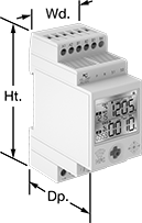
Control two steps of an electrical process from a single relay—with two fully independent channels and 30 different functions, these relays give you a wide range of possibilities. Each channel has its own output, so you can run two different functions (one per circuit) at the same time. Mount them to 35 mm DIN rails (also known as DIN 3 rail) and connect them to lighting systems, conveyors, electric motors, and other systems. These relays are UL Listed, C-UL Listed, and CE Marked, meaning they meet U.S. and international safety standards.
View times, function names, and on/off status for both channels at once using the digital display. You can program these relays with a joystick on the face, which is easier to use than the rotary dials on traditional relays. You can also program them using an Android phone with NFC (near field communication) capability, which is commonly used for mobile payment. Once you select the functions you need, hold the phone against the relay to program.
Connect switches to inputs on these relays to trigger, pause, and reset functions. Turning on a switch connected to the pause input stops functions until the switch is turned off. A switch connected to the reset input will start functions from the beginning. If the relay is actively receiving a signal, the function will restart right away. If there is no signal, the function will stop and reset, so it starts from the beginning the next time it’s triggered. You can use switches to pause or reset both channels at once, or for one channel only.
Use relays with proximity sensor compatibility to activate functions when your sensor is triggered, such as when an object approaches or a liquid level changes. These relays are compatible with both standard styles of sensors, PNP and NPN, and are often used for warning signals, motion-detecting light and heating systems, and automated assembly lines.
Although these relays have 30 different functions, they all fall into 10 categories. Within these categories, you can select different functions to allow you to add a switch, program a delay, or change how the relay responds to a trigger (turning on or off, pausing, or resetting).
Manual Switch Control—Use these functions to turn the relay on and off with a switch.
Fixed On/Off—The on function keeps the relay on whenever input voltage is applied; it will only turn off if the voltage is removed. The off function keeps the relay in an off state, even if input voltage is applied.
Switch-On (Single-Shot)—These functions require a switch to activate the relay, which stays on for the programmed amount of time. For example, lights in a storage room are turned on with a switch and stay on for a set time before turning off.
Delayed Start (Delay-on-Make)—These functions allow you to set how long it takes for the relay to turn on after input voltage is applied. For example, a drill starts pumping lubricant immediately, but it does not start rotating until the set time has elapsed.
Delayed Switch-Off (Delay-on-Break)—These functions use a switch instead of input voltage. When the switch is turned off, the relay remains on for a programmed amount of time before turning off. For example, a projector’s light is turned off with a switch, but its cooling fan continues to run for a set time.
Delayed Switch-On with Delayed Switch-Off—This function uses a switch instead of an input voltage. It allows you to set how long it takes the relay to turn on after a switch is turned on, and how long it will stay on after the switch is turned off. For example, a furnace turns on, but the fan doesn’t start pushing air through the vents until it has been heated. When the furnace turns off, the fan keeps blowing to circulate all the hot air.
Interval—These functions use input voltage to turn on the relay for a programmed amount of time. For example, when a part moving down a conveyor reaches a certain location, a cleaning spray comes on for a set amount of time.
Repeat Cycle—When input voltage is applied, the relay turns on for a duration, then off for the same duration. They alternate between the two until input voltage is removed. For example, a flashing light stays on and off for equal periods of time.
Asymmetrical Repeat Cycle—These functions start with an on-cycle and then have an off-cycle, but these cycles have different durations. The cycles repeat until input voltage is removed. For example, a sprinkler system sprays in short bursts followed by longer rest periods, on and off until input voltage is removed.
Switch-On Asymmetrical Repeat Cycle—These functions require a switch to activate the timing function. The input voltage is applied the whole time, and when you turn the switch on, the relay begins with an on-cycle followed by an off-cycle. These cycles have different durations, and they repeat until you turn the switch off. They could be used to turn on a motor or other system for a short period and then turn it off for a longer rest period, repeating that pattern until the switch is turned off.
For technical drawings and 3-D models, click on a part number.
Timing Range | |||||||||||||
|---|---|---|---|---|---|---|---|---|---|---|---|---|---|
| No. of Terminals | Input Voltage | Control Current, mA | Timer Relay Function | No. of | Overall | Switching Current @ 240V AC | Max. Switching Voltage | Ht. | Wd. | Dp. | Features | Each | |
2 Circuit Controlled with 2 Off (Normally Open) and 2 On (Normally Closed)—DPDT | |||||||||||||
| 12 | 12V AC, 24V AC, 12V DC, 24V DC | 8 | Manual Switch Control Fixed On/Off Switch-On (Single-Shot) Delayed Start (Delay-on-Make) Delayed Switch-Off (Delay-on-Break) Delayed Switch-On with Delayed Switch-Off Interval Repeat Cycle Asymmetrical Repeat Cycle Switch-On Asymmetrical Repeat Cycle | 30 | 0.1 sec.-9,999 hrs. | 16A | 240V AC | 3.4" | 1.4" | 2.2" | 2 Individually Programmable Timers, LCD Screen, Proximity Sensor Compatability (PNP and NPN) | 0000000 | 0000000 |
| 12 | 120V AC, 240V AC, 110V DC, 240V DC | 16 | Manual Switch Control Fixed On/Off Switch-On (Single-Shot) Delayed Start (Delay-on-Make) Delayed Switch-Off (Delay-on-Break) Delayed Switch-On with Delayed Switch-Off Interval Repeat Cycle Asymmetrical Repeat Cycle Switch-On Asymmetrical Repeat Cycle | 30 | 0.1 sec.-9,999 hrs. | 16A | 240V AC | 3.4" | 1.4" | 2.2" | 2 Individually Programmable Timers, LCD Screen | 0000000 | 000000 |
Solid State Versa-Mount Multifunction Timer Relays
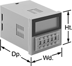
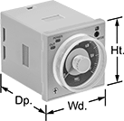
Install these relays in a panel cutout or plug them into a relay socket. Unlike mechanical relays, these solid state relays have no moving parts, so they require less maintenance and last longer, are quieter, and switch faster. They give you a variety of timing functions in one relay.
Single-circuit relays give you additional flexibility—they have two types of delayed switch-off (delay-on-break) functions and two types of signal on/off delay functions.
Relay sockets (sold separately) mount to
Mounting brackets (sold separately) are required to mount relays into a panel cutout.
Timer Relays | |||||||||||||
|---|---|---|---|---|---|---|---|---|---|---|---|---|---|
Timing Range | Relay Sockets | ||||||||||||
| No. of Terminals | Input Voltage | Control Current, mA | Timer Relay Function | No. of | Overall | Switching Current @ 240V AC | Ht. | Wd. | Dp. | Each | Each | ||
1 Circuit Controlled with 1 Off (Normally Open) or 1 On (Normally Closed)—SPDT | |||||||||||||
| 11 | 24V AC, 48V AC, 120V AC, 240V AC, 12V DC, 24V DC, 48V DC, 60V DC, 120V DC, 240V DC | 17 | Delayed Start (Delay-on-Make) Interval Switch-On (Single-Shot) Delayed Switch-Off (Delay-on-Break) Repeat Cycle | 7 | 0.1 sec.-999 hrs. | 3A | 1.9" | 1.9" | 2.7" | 0000000 | 0000000 | 0000000 | 000000 |
2 Circuits Controlled with 2 Off (Normally Open) or 2 On (Normally Closed)—DPDT | |||||||||||||
| 8 | 120V AC, 240V AC, 110V DC, 120V DC | 13 | Delayed Start (Delay-on-Make) Interval Switch-On (Single-Shot) Repeat Cycle | 4 | 0.05 sec.-300 hrs. | 5A | 1.9" | 1.9" | 2.3" | 00000000 | 000000 | 0000000 | 0000 |
Mounting Hole | ||||||||||
|---|---|---|---|---|---|---|---|---|---|---|
| Material | Mounting Location | No. of | Ctr.-to-Ctr. | Dia. | Mounting Fasteners Included | Screw Size | Ht. | Wd. | Each | |
| Polycarbonate | Panel | 2 | 3" | 5mm | Yes | M5 | 2.28" | 1.89" | 0000000 | 000000 |
Multifunction Timer Relays
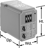
Get a variety of timing functions in a single relay. All relays plug into relay sockets (sold separately) for fast installation and replacement.
Relay socket/panel mount relays require a mounting bracket (sold separately) to mount in a panel cutout.
Relay sockets mount to 35 mm DIN rail (also known as DIN 3 rail) or can be mounted to a flat surface.
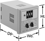

Timer Relays | ||||||||||||||
|---|---|---|---|---|---|---|---|---|---|---|---|---|---|---|
Timing Range | Relay Sockets | |||||||||||||
| Number of Terminals | Input Voltage | Control Current, mA | Timer Relay Function | No. of | Overall | Switching Current @ 240V AC | Max. Switching Voltage | Ht. | Wd. | Dp. | Each | Each | ||
2 Circuits Controlled with 2 Off (Normally Open) or 2 On (Normally Closed)—DPDT | ||||||||||||||
Relay Socket Mounting Location | ||||||||||||||
| 11 | 24V AC | 83 | Delayed Start (Delay-on-Make) Interval Switch-On (Single-Shot) Delayed Switch-Off (Delay-on-Break) Repeat Cycle | 5 | 0.05 sec.-999 min. | 10A | 240V AC | 2.4" | 1.8" | 3.7" | 0000000 | 0000000 | 0000000 | 000000 |
| 11 | 120V AC | 17 | Delayed Start (Delay-on-Make) Interval Switch-On (Single-Shot) Delayed Switch-Off (Delay-on-Break) Repeat Cycle | 5 | 0.05 sec.-999 min. | 10A | 240V AC | 2.4" | 1.8" | 3.7" | 0000000 | 000000 | 0000000 | 00000 |
| 11 | 240V AC | 8 | Delayed Start (Delay-on-Make) Interval Switch-On (Single-Shot) Delayed Switch-Off (Delay-on-Break) Repeat Cycle | 5 | 0.05 sec.-999 min. | 10A | 240V AC | 2.4" | 1.8" | 3.7" | 0000000 | 000000 | 0000000 | 00000 |
| 11 | 12V DC | 167 | Delayed Start (Delay-on-Make) Interval Switch-On (Single-Shot) Delayed Switch-Off (Delay-on-Break) Repeat Cycle | 5 | 0.05 sec.-999 min. | 10A | 240V AC | 2.4" | 1.8" | 3.7" | 0000000 | 000000 | 0000000 | 00000 |
| 11 | 24V DC | 83 | Delayed Start (Delay-on-Make) Interval Switch-On (Single-Shot) Delayed Switch-Off (Delay-on-Break) Repeat Cycle | 5 | 0.05 sec.-999 min. | 10A | 240V AC | 2.4" | 1.8" | 3.7" | 0000000 | 000000 | 0000000 | 00000 |
Relay Socket/Panel Mounting Location | ||||||||||||||
| 11 | 24V AC, 48V AC, 120V AC, 240V AC, 24V DC, 48V DC, 60V DC, 120V DC, 240V DC | 104 | Delayed Start (Delay-on-Make) Interval Switch-On (Single-Shot) Delayed Switch-Off (Delay-on-Break) Repeat Cycle | 6 | 0.05 sec.-999 hrs. | 10A | 240V AC | 1.9" | 1.9" | 2.8" | 000000 | 000000 | 0000000 | 00000 |

Mounting Hole | ||||||||||
|---|---|---|---|---|---|---|---|---|---|---|
| Material | Mounting Location | No. of | Ctr.-to-Ctr. | Dia. | Mounting Fasteners Included | Screw Size | Ht. | Wd. | Each | |
| Polycarbonate | Panel | 2 | 3" | 5mm | Yes | M5 | 2.28" | 1.89" | 0000000 | 000000 |
Solid State DIN-Rail Mount Multifunction Timer Relays

Quick-Disconnect
Terminals
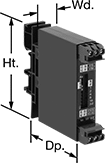
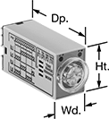
For fast installation, mount these relays to 35 mm DIN rail (also known as DIN 3 rail). They also mount to flat surfaces. With no moving parts, these solid state relays last longer and require less maintenance, are quieter, and switch faster than mechanical relays. They provide a variety of timing functions in one relay.
Use relays with DIP switches for more precise control than knobs. They make it easier to set multiple relays to the same timing range.
Relays that control 4 circuits require a relay socket (sold separately) to attach to DIN rail.
Timer Relays | |||||||||||||||
|---|---|---|---|---|---|---|---|---|---|---|---|---|---|---|---|
Timing Range | Relay Sockets | ||||||||||||||
| No. of Terminals | Input Voltage | Control Current, mA | Timer Relay Function | No. of | O'all | Switching Current @ 240V AC | Max. Switching Voltage | Ht. | Wd. | Dp. | Wire Connection Type | Each | Each | ||
Relays with DIP Switches | |||||||||||||||
1 Circuit Control with 1 Off (Normally Open)—SPST-NO | |||||||||||||||
| 4 | 24V AC, 48V AC, 120V AC, 240V AC | 8 | Delayed Start (Delay-on-Make) Interval Switch-On (Single-Shot) Delayed Switch-Off (Delay-on-Break) Repeat Cycle | 4 | 0.1 sec.-63 min. | 0.7A | 240V AC | 3" | 0.7" | 2.4" | Quick-Disconnect Terminals | 0000000 | 000000 | 000000 | 00 |
| 4 | 9V DC, 12V DC, 24V DC, 48V DC, 60V DC, 110V DC | 8 | Delayed Start (Delay-on-Make) Interval Switch-On (Single-Shot) Delayed Switch-Off (Delay-on-Break) Repeat Cycle | 4 | 0.1 sec.-63 min. | 0.7A | 240V AC | 3" | 0.7" | 2.4" | Quick-Disconnect Terminals | 0000000 | 00000 | 000000 | 00 |
| 6 | 24V AC, 48V AC, 120V AC, 240V AC | 8 | Delayed Start (Delay-on-Make) Interval Switch-On (Single-Shot) Delayed Switch-Off (Delay-on-Break) Repeat Cycle | 4 | 0.1 sec.-63 min. | 0.7A | 240V AC | 3" | 0.7" | 2.4" | Screw Terminals | 0000000 | 000000 | 000000 | 00 |
| 6 | 9V DC, 12V DC, 24V DC, 48V DC, 60V DC, 110V DC | 8 | Delayed Start (Delay-on-Make) Interval Switch-On (Single-Shot) Delayed Switch-Off (Delay-on-Break) Repeat Cycle | 4 | 0.1 sec.-63 min. | 0.7A | 240V AC | 3" | 0.7" | 2.4" | Screw Terminals | 0000000 | 000000 | 000000 | 00 |
Relays with Knob | |||||||||||||||
1 Circuit Control with 1 Off (Normally Open)—SPST-NO | |||||||||||||||
| 4 | 24V AC, 48V AC, 120V AC, 240V AC | 8 | Delayed Start (Delay-on-Make) Interval Switch-On (Single-Shot) Delayed Switch-Off (Delay-on-Break) Repeat Cycle | 4 | 0.1 sec.-100 min. | 0.7A | 240V AC | 3" | 0.7" | 2.4" | Quick-Disconnect Terminals | 0000000 | 00000 | 000000 | 00 |
| 4 | 9V DC, 12V DC, 24V DC, 48V DC, 60V DC, 110V DC | 8 | Delayed Start (Delay-on-Make) Interval Switch-On (Single-Shot) Delayed Switch-Off (Delay-on-Break) Repeat Cycle | 4 | 0.1 sec.-100 min. | 0.7A | 240V AC | 3" | 0.7" | 2.4" | Quick-Disconnect Terminals | 0000000 | 00000 | 000000 | 00 |
| 6 | 24V AC, 48V AC, 120V AC, 240V AC | 8 | Delayed Start (Delay-on-Make) Interval Switch-On (Single-Shot) Delayed Switch-Off (Delay-on-Break) Repeat Cycle | 4 | 0.1 sec.-100 min. | 0.7A | 240V AC | 3" | 0.7" | 2.4" | Screw Terminals | 0000000 | 000000 | 000000 | 00 |
| 6 | 9V DC, 12V DC, 24V DC, 48V DC, 60V DC, 110V DC | 8 | Delayed Start (Delay-on-Make) Interval Switch-On (Single-Shot) Delayed Switch-Off (Delay-on-Break) Repeat Cycle | 4 | 0.1 sec.-100 min. | 0.7A | 240V AC | 3" | 0.7" | 2.4" | Screw Terminals | 0000000 | 000000 | 000000 | 00 |
4 Circuit Control with 4 Off (Normally Open) or 4 On (Normally Closed)—4PDT | |||||||||||||||
| 14 | 120V AC | 15 | Delayed Start (Delay-on-Make) Interval Repeat Cycle | 4 | 0.1 sec.-10 min. | 3A | 250V AC | 1.1" | 0.9" | 2.1" | __ | 000000 | 000000 | 0000000 | 000000 |
| 14 | 240V AC | 9 | Delayed Start (Delay-on-Make) Interval Repeat Cycle | 4 | 0.1 sec.-10 min. | 3A | 250V AC | 1.1" | 0.9" | 2.1" | __ | 000000 | 000000 | 0000000 | 00000 |
| 14 | 24V DC | 45 | Delayed Start (Delay-on-Make) Interval Repeat Cycle | 4 | 0.1 sec.-10 min. | 3A | 250V AC | 1.1" | 0.9" | 2.1" | __ | 000000 | 000000 | 0000000 | 00000 |
Solid State DIN-Rail Mount Multifunction Interface Timer Relays

Considered solid state because they don’t have any moving parts, these timer relays last longer, switch faster, and are quieter than mechanical relays. They interface between your controller and components to isolate input and output circuits, preventing damage to your components from voltage spikes, amplifying the relay's signal, and reducing signal interference. Use these relays with switching applications, such as small motors and pilot lights. They offer multiple timing functions in one relay. The included relay socket mounts on 35 mm DIN rail (also known as DIN 3 rail) for fast installation. Relays disconnect from the socket for easy replacement.
Relays with Relay Sockets | ||||||||||||||
|---|---|---|---|---|---|---|---|---|---|---|---|---|---|---|
Timing Range | Replacement Relays | |||||||||||||
| No. of Terminals | Input Voltage | Control Current, mA | Timer Relay Function | No. of | Overall | Switching Current @ Voltage | Max. Switching Voltage | Ht. | Wd. | Dp. | Each | Each | ||
1 Circuit Controlled with 1 Off (Normally Open)—SPST-NO | ||||||||||||||
| 5 | 24V AC, 24V DC | 12 | Delayed Start (Delay-on-Make) Interval Repeat Cycle | 4 | 0.1 sec.-6 hrs. | 2 A @ 240 V AC | 275V AC | 3 1/2" | 0.2" | 2.8" | 0000000 | 000000 | 0000000 | 000000 |
| 5 | 24V AC, 24V DC | 12 | Delayed Start (Delay-on-Make) Interval Repeat Cycle | 4 | 0.1 sec.-6 hrs. | 6 A @ 24 V DC | 33V DC | 3 1/2" | 0.2" | 2.8" | 0000000 | 00000 | 0000000 | 00000 |
Timer Relays


Turn machinery, such as paint and conveyor lines, on and off after a set period of time. These timer relays plug into relay sockets (sold separately) for fast installation and replacement.
Relay sockets mount on 35 mm DIN rail (also known as DIN 3) or flat surfaces.
For technical drawings and 3-D models, click on a part number.
Timer Relays | |||||||||||||
|---|---|---|---|---|---|---|---|---|---|---|---|---|---|
Timing Range | Switching Current | Relay Sockets | |||||||||||
| Number of Terminals | Input Voltage | Control Current, mA | No. of | Overall | @ 240V AC | @ 24V DC | Max. Switching Voltage | hp @ Switching Voltage | Timing Adjustment Style | Each | Each | ||
Repeat Cycle | |||||||||||||
2 Circuits Controlled with 2 Off (Normally Open) or 2 On (Normally Closed)—DPDT | |||||||||||||
| 8 | 24V AC | 135 | 1 | 1 sec.-1,023 sec. | 10A | 10A | 240V AC/30V DC | 1/3 hp @ 240 V AC | DIP Switches | 00000000 | 0000000 | 0000000 | 00000 |
| 8 | 120V AC | 27 | 1 | 1 sec.-1,023 sec. | 10A | 10A | 240V AC/30V DC | 1/3 hp @ 240 V AC | DIP Switches | 00000000 | 000000 | 0000000 | 0000 |
| 8 | 240V AC | 14 | 1 | 1 sec.-1,023 sec. | 10A | 10A | 240V AC/30V DC | 1/3 hp @ 240 V AC | DIP Switches | 00000000 | 000000 | 0000000 | 0000 |
| 8 | 24V AC, 24V DC | 83 | 1 | 0.1 sec.-10 sec. | 10A | 8A | 240V AC/30V DC | 1/3 hp @ 240 V AC | Knob | 0000000 | 000000 | 0000000 | 0000 |
| 8 | 24V AC, 24V DC | 83 | 1 | 0.6 sec.-60 sec. | 10A | 8A | 240V AC/30V DC | 1/3 hp @ 240 V AC | Knob | 0000000 | 000000 | 0000000 | 0000 |
| 8 | 24V AC, 24V DC | 83 | 1 | 1.8 sec.-180 sec. | 10A | 8A | 240V AC/30V DC | 1/3 hp @ 240 V AC | Knob | 0000000 | 000000 | 0000000 | 0000 |
| 8 | 120V AC, 120V DC | 17 | 1 | 0.05 sec.-5 sec. | 10A | 8A | 240V AC/30V DC | 1/3 hp @ 240 V AC | Knob | 0000000 | 000000 | 0000000 | 0000 |
| 8 | 120V AC, 120V DC | 17 | 1 | 0.1 min.-10 min. | 10A | 8A | 240V AC/30V DC | 1/3 hp @ 240 V AC | Knob | 0000000 | 000000 | 0000000 | 0000 |
| 8 | 120V AC, 120V DC | 17 | 1 | 0.1 sec.-10 sec. | 10A | 8A | 240V AC/30V DC | 1/3 hp @ 240 V AC | Knob | 0000000 | 000000 | 0000000 | 0000 |
| 8 | 120V AC, 120V DC | 17 | 1 | 0.3 min.-30 min. | 10A | 8A | 240V AC/30V DC | 1/3 hp @ 240 V AC | Knob | 0000000 | 000000 | 0000000 | 0000 |
| 8 | 120V AC, 120V DC | 17 | 1 | 0.6 sec.-60 sec. | 10A | 8A | 240V AC/30V DC | 1/3 hp @ 240 V AC | Knob | 0000000 | 000000 | 0000000 | 0000 |
| 8 | 120V AC, 120V DC | 17 | 1 | 1.8 sec.-180 sec. | 10A | 8A | 240V AC/30V DC | 1/3 hp @ 240 V AC | Knob | 0000000 | 000000 | 0000000 | 0000 |
| 8 | 120V AC, 120V DC | 17 | 1 | 3 sec.-300 sec. | 10A | 8A | 240V AC/30V DC | 1/3 hp @ 240 V AC | Knob | 0000000 | 000000 | 0000000 | 0000 |
| 8 | 12V DC | 170 | 1 | 1.8 sec.-180 sec. | 10A | 8A | 240V AC/30V DC | 1/3 hp @ 240 V AC | Knob | 0000000 | 00000 | 0000000 | 0000 |
| 8 | 12V DC | 271 | 1 | 1 sec.-1,023 sec. | 10A | 10A | 240V AC/30V DC | 1/3 hp @ 240 V AC | DIP Switches | 00000000 | 000000 | 0000000 | 0000 |
| 8 | 24V DC | 135 | 1 | 1 sec.-1,023 sec. | 10A | 10A | 240V AC/30V DC | 1/3 hp @ 240 V AC | DIP Switches | 00000000 | 000000 | 0000000 | 0000 |
DIN-Rail Mount Multifunction Interface Timer Relays

Protect components from voltage spikes while amplifying the relay’s signal and reducing interference for reliable transmission—these relays interface between your controller and system components to isolate the input and output circuits. They are often used for switching applications, such as small motors and pilot lights. These relays provide a variety of timing functions in one relay. The included relay socket mounts on 35 mm DIN rail (also known as DIN 3 rail) for fast installation. Relays disconnect from the socket for easy replacement.
Relays with Relay Sockets | ||||||||||||||
|---|---|---|---|---|---|---|---|---|---|---|---|---|---|---|
Timing Range | Replacement Relays | |||||||||||||
| No. of Terminals | Input Voltage | Control Current, mA | Timer Relay Function | No. of | Overall | Switching Current @ 240V AC | Max. Switching Voltage | Ht. | Wd. | Dp. | Each | Each | ||
1 Circuit Controlled with 1 Off (Normally Open) or 1 On (Normally Closed)—SPDT | ||||||||||||||
| 5 | 24V AC, 24V DC | 16 | Delayed Start (Delay-on-Make) Interval Repeat Cycle | 4 | 0.1 sec.-6 hrs. | 6A | 240V AC | 3 1/2" | 0.2" | 2.8" | 0000000 | 000000 | 0000000 | 00000 |
Solid State Versa-Mount Timer Relays
Mount these timer relays in a panel cutout or plug them into a relay socket for quick installation. Capable of fast switching, they are solid state and have no moving parts, so they require less maintenance, last longer, and are quieter than mechanical relays. Unlike standard relays that switch on and off immediately, timer relays delay before the circuit stops or starts.
Relays with a repeat cycle alternate between an on cycle and off cycle of equal durations until input voltage is removed. A common example would be a flashing light.
Relays with an asymmetrical repeat cycle begin in an on state, then alternate between different durations of off and on for as long as input voltage is applied. For example, a heating system starts with an on period, then switches to an off period once the desired temperature is reached.
Relay sockets (sold separately) mount to 35 mm DIN rail (also known as DIN 3 rail) or can be mounted to a flat surface.
Mounting brackets (sold separately) are required to mount the relay into a panel.
For technical drawings and 3-D models, click on a part number.
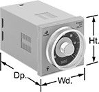

Timer Relays | ||||||||||||
|---|---|---|---|---|---|---|---|---|---|---|---|---|
Timing Range | Relay Sockets | |||||||||||
| Number of Terminals | Input Voltage | Control Current, mA | No. of | Overall | Switching Current @ 240V AC | Ht. | Wd. | Dp. | Each | Each | ||
Repeat Cycle | ||||||||||||
2 Circuits Controlled with 2 Off (Normally Open) or 2 On (Normally Closed)—DPDT | ||||||||||||
| 8 | 120V AC, 240V AC, 110V DC, 120V DC | 100 | 4 | 0.05 sec.-300 hrs. | 5A | 1.9" | 1.9" | 3.3" | 00000000 | 0000000 | 0000000 | 00000 |
Asymmetrical Repeat Cycle | ||||||||||||
2 Circuits Controlled with 2 Off (Normally Open) or 2 On (Normally Closed)—DPDT | ||||||||||||
| 8 | 24V AC, 48V AC, 12V DC, 24V DC, 48V DC | 83 | 4 | 0.05 sec.-300 hrs. | 5A | 1.9" | 1.9" | 3.3" | 000000000 | 000000 | 0000000 | 0000 |
| 8 | 120V AC, 240V AC, 110V DC, 120V DC | 41 | 4 | 0.05 sec.-300 hrs. | 5A | 1.9" | 1.9" | 3.3" | 000000000 | 000000 | 0000000 | 0000 |
| 11 | 24V AC, 48V AC, 12V DC, 24V DC, 48V DC | 83 | 4 | 0.05 sec.-300 hrs. | 5A | 1.9" | 1.9" | 3.3" | 0000000 | 000000 | 0000000 | 00000 |
| 11 | 120V AC, 240V AC, 110V DC, 120V DC | 41 | 4 | 0.05 sec.-300 hrs. | 5A | 1.9" | 1.9" | 3.3" | 0000000 | 000000 | 0000000 | 00000 |

Mounting Hole | ||||||||||
|---|---|---|---|---|---|---|---|---|---|---|
| Material | Mounting Location | No. of | Ctr.-to-Ctr. | Dia. | Mounting Fasteners Included | Screw Size | Ht. | Wd. | Each | |
| Polycarbonate | Panel | 2 | 3" | 5mm | Yes | M5 | 2.28" | 1.89" | 0000000 | 000000 |
Solid State Surface-Mount Timer Relays
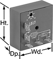
Attach these relays to a flat surface using the mounting hole. They have no moving parts, so compared to mechanical switches, they require less maintenance, last longer, and are quieter.
Repeat cycle relays turn on for a duration, then off for the same duration. They alternate between the two cycles until input voltage is removed. A common example would be a flashing light.
For technical drawings and 3-D models, click on a part number.
Timing Range | ||||||||||||
|---|---|---|---|---|---|---|---|---|---|---|---|---|
| Number of Terminals | Input Voltage | Control Current, mA | No. of | Overall | Switching Current @ Voltage | Max. Switching Voltage | hp @ Switching Voltage | Ht. | Wd. | Dp. | Each | |
Repeat Cycle | ||||||||||||
1 Circuit Controlled with 1 Off (Normally Open)—SPST-NO | ||||||||||||
| 7 | 120V AC | 36 | 1 | 0.05 sec.-1 sec. | 1 A @ 120 V AC | __ | __ | 2" | 2" | 0.88" | 00000000 | 000000 |
| 7 | 120V AC | 36 | 1 | 3 sec.-60 sec. | 1 A @ 120 V AC | __ | __ | 2" | 2" | 0.88" | 00000000 | 00000 |
| 7 | 120V AC | 36 | 1 | 30 sec.-10 min. | 1 A @ 120 V AC | __ | __ | 2" | 2" | 0.88" | 00000000 | 00000 |
1 Circuit Controlled with 1 Off (Normally Open) or 1 On (Normally Closed)—SPDT | ||||||||||||
| 5 | 120V AC | 36 | 1 | 0.1 sec.-10 sec. | 30 A @ 240 V AC/24 V DC | 240V AC | 1 hp @ 120 V AC 2 hp @ 240 V AC | 3" | 2" | 1.4" | 00000000 | 00000 |
| 5 | 120V AC | 36 | 1 | 0.1 min.-10 min. | 30 A @ 240 V AC/24 V DC | 240V AC | 1 hp @ 120 V AC 2 hp @ 240 V AC | 3" | 2" | 1.4" | 00000000 | 00000 |
| 5 | 120V AC | 36 | 1 | 1 min.-100 min. | 30 A @ 240 V AC/24 V DC | 240V AC | 1 hp @ 120 V AC 2 hp @ 240 V AC | 3" | 2" | 1.4" | 00000000 | 00000 |
| 5 | 24V DC | 41 | 1 | 0.1 sec.-10 sec. | 30 A @ 240 V AC/24 V DC | 240V AC | 1 hp @ 120 V AC 2 hp @ 240 V AC | 3" | 2" | 1.4" | 00000000 | 00000 |
| 5 | 24V DC | 41 | 1 | 0.1 min.-10 min. | 30 A @ 240 V AC/24 V DC | 240V AC | 1 hp @ 120 V AC 2 hp @ 240 V AC | 3" | 2" | 1.4" | 00000000 | 00000 |
| 5 | 24V DC | 41 | 1 | 1 min.-100 min. | 30 A @ 240 V AC/24 V DC | 240V AC | 1 hp @ 120 V AC 2 hp @ 240 V AC | 3" | 2" | 1.4" | 00000000 | 00000 |
Smart DIN-Rail Mount Multifunction Timer Relays


Whether installed in an electrical cabinet or hard-to-reach area, these timer relays are controlled remotely from your smartphone. They connect to your phone via a free downloadable app with NFC (Near Field Communication), so you can set time delay ranges, adjust settings, and save programs. An LED indicator on the relay shows that your switch is on and whether it’s actuated. Mount them directly to 35 mm DIN rail (also known as DIN 3 rail).
Although these relays have 30 different functions, they all fall into 11 categories. Within these categories, you can select different functions to allow you to add a switch, program a delay, or change how the relay responds to a trigger (turning on or off, pausing, or resetting).
Manual Switch Control—Use these functions to turn the relay on and off with a switch.
Fixed On/Off—The on function keeps the relay on whenever input voltage is applied; it will only turn off if the voltage is removed. The off function keeps the relay in an off state, even if input voltage is applied.
Switch-On (Single-Shot)—These functions require a switch to activate the relay, which stays on for the programmed amount of time. For example, lights in a storage room are turned on with a switch and stay on for a set time before turning off.
Delayed Start (Delay-on-Make)—These functions allow you to set how long it takes for the relay to turn on after input voltage is applied. For example, a drill starts pumping lubricant immediately, but it does not start rotating until the set time has elapsed.
Delayed Switch-Off (Delay-on-Break)—These functions use a switch instead of input voltage. When the switch is turned off, the relay remains on for a programmed amount of time before turning off. For example, a projector’s light is turned off with a switch, but its cooling fan continues to run for a set time.
Delayed Switch-On with Delayed Switch-Off—This function uses a switch instead of an input voltage. It allows you to set how long it takes the relay to turn on after a switch is turned on, and how long it will stay on after the switch is turned off. For example, a furnace turns on, but the fan doesn’t start pushing air through the vents until it has been heated. When the furnace turns off, the fan keeps blowing to circulate all the hot air.
Interval—These functions use input voltage to turn on the relay for a programmed amount of time. For example, when a part moving down a conveyor reaches a certain location, a cleaning spray comes on for a set amount of time.
Repeat Cycle—These functions start with an on cycle and then alternate between an on cycle and off cycle of equal durations until input voltage is removed, such as with a flashing light.
Asymmetrical Repeat Cycle—These functions start with an on-cycle and then have an off-cycle, but these cycles have different durations. The cycles repeat until input voltage is removed. For example, a sprinkler system sprays in short bursts followed by longer rest periods, on and off until input voltage is removed.
Switch-On Asymmetrical Repeat Cycle—These functions require a switch to activate the timing function. The input voltage is applied the whole time, and when you turn the switch on, the relay begins with an on-cycle followed by an off-cycle. These cycles have different durations, and they repeat until you turn the switch off. They could be used to turn on a motor or other system for a short period and then turn it off for a longer rest period, repeating that pattern until the switch is turned off.
Star-to-Delta—These functions allow you to set the time delay within the relay's range to switch contacts on a three-phase motor from star to delta configuration. Since star configuration takes less voltage to start than delta, these functions prevent voltage dips that often happen when a motor starts and are gentler on mechanical parts.
For technical drawings and 3-D models, click on a part number.
| No. of Terminals | Input Voltage | Control Power, W | Timer Relay Function | O'all Timing Range | Switching Current @ 240V AC | Max. Switching Voltage | Ht. | Wd. | Dp. | Operating System Compatibility | Features | Each | |
1 Circuit Controlled with 1 Off (Normally Open) or 1 On (Normally Closed)—SPDT | |||||||||||||
|---|---|---|---|---|---|---|---|---|---|---|---|---|---|
| 8 | 12V AC, 24V AC, 48V AC, 120V AC, 240V AC, 12V DC, 24V DC, 48V DC, 60V DC, 120V DC, 240V DC | 0.15 | Manual Switch Control Fixed On/Off Switch-On (Single-Shot) Delayed Start (Delay-on-Make) Delayed Switch-Off (Delay-on-Break) Delayed Switch-On with Delayed Switch-Off Interval Repeat Cycle Asymmetrical Repeat Cycle Switch-On Asymmetrical Repeat Cycle | 0.1 sec.-999 days | 8A | 250V AC | 4.1" | 0.7" | 2.5" | Android 5.0 or Later, iOS 14.4 or Later | LED Indicator | 0000000 | 000000 |
2 Circuits Controlled with 2 Off (Normally Open) or 2 On (Normally Closed)—DPDT | |||||||||||||
| 9 | 24V AC, 48V AC, 120V AC, 240V AC, 24V DC, 48V DC, 60V DC, 120V DC, 240V DC | 0.6 | Manual Switch Control Fixed On/Off Switch-On (Single-Shot) Delayed Start (Delay-on-Make) Delayed Switch-Off (Delay-on-Break) Delayed Switch-On with Delayed Switch-Off Interval Repeat Cycle Asymmetrical Repeat Cycle Switch-On Asymmetrical Repeat Cycle Star-to-Delta | 0.1 sec.-999 hrs. | 8A | 250V AC | 3.5" | 0.9" | 2.9" | Android 4.4 or Later, iOS 14.5 or Later | LED Indicator | 0000000 | 00000 |
Compact Programmable Logic Controllers
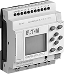
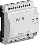
Smaller than other PLCs, these controllers save space in your control cabinet. They combine the functionality of a relay, timer relay, and switch in one unit, so you can program simple automation jobs. All have two types of delayed start (delay-on-make) and two types of delayed switch-off (delay-on-break) timing functions. They have passed strict U.S. and Canadian safety standards, and they’re IP20, which prevents fingers and other objects from making contact with live circuits. Mount them to a 35-mm DIN rail.
Controllers with a display make it easy to monitor or modify your system directly on the unit. Controllers without a display eliminate the risk of accidental adjustments while toggling through information or tampering by unauthorized users.
Program these controllers by connecting them to a computer and installing the required software (sold separately). After the initial programming, these controllers can be updated remotely by a human-machine interface (HMI) or computer.
For technical drawings and 3-D models, click on a part number.
Digital Inputs | Digital Outputs | ||||||||||
|---|---|---|---|---|---|---|---|---|---|---|---|
| Input Signal Type | Voltage | No. of | Voltage | Current | No. of | Signal Type | Operating Voltage | Communication Protocol | Software Included | Each | |
Controllers with Display | |||||||||||
Eaton Easy E4 Series | |||||||||||
| __ | 100-240V AC 100-240V DC | 8 | 240V AC | 8A | 4 | Relay | 100-240V AC 100-240V DC | Modbus TCP/IP | No | 000000 | 0000000 |
| Digital, Analog | 12V DC 24V AC 24V DC 0-10V DC | 8 (4 can be analog) | 240V AC | 8A | 4 | Relay | 12V DC 24V AC 24V DC | Modbus TCP/IP | No | 000000 | 000000 |
| Digital, Analog | 24V DC 0-10V DC | 8 (4 can be analog) | 24V DC | 0.5A | 4 | Transistor | 24V DC | Modbus TCP/IP | No | 0000000 | 000000 |
Controllers without Display | |||||||||||
Eaton Easy E4 Series | |||||||||||
| __ | 100-240V AC 100-240V DC | 8 | 240V AC | 8A | 4 | Relay | 100-240V AC 100-240V DC | Modbus TCP/IP | No | 0000000 | 000000 |
| Digital, Analog | 12V DC 24V AC 24V DC 0-10V DC | 8 (4 can be analog) | 240V AC | 8A | 4 | Relay | 12V DC 24V AC 24V DC | Modbus TCP/IP | No | 0000000 | 000000 |
| Digital, Analog | 24V DC 0-10V DC | 8 (4 can be analog) | 24V DC | 0.5A | 4 | Transistor | 24V DC | Modbus TCP/IP | No | 0000000 | 000000 |
| Manufacturer Model Number | For Operating System | Media Type | Each | |
For Eaton Easy E4 Series | ||||
|---|---|---|---|---|
| EASYSOFT-SWLIC/EasySoft 7 | Windows 7, Windows 8, Windows 8.1, Windows 10 | Download | 000000 | 000000 |
Time-Delay Photoelectric Switches with Relay Output

Set these switches to delay activation by up to five seconds after detecting an object. A built-in relay produces AC voltage output. They’re often used with older programmable logic controllers (PLCs). They detect the presence or absence of an object moving at high speeds with a light beam. All are rated IP66 for protection against washdowns.
Direct sensing switches detect objects when light reflects back from the object. The transmitter and receiver are in the same housing, so they fit in confined spaces.
Receiver switches detect objects when an object breaks the light beam between the transmitter and receiver (both included). They have a longer sensing distance than direct-sensing and reflector switches.
Reflector switches detect an object when it passes between the switch and the reflector, interrupting the beam. They have a longer sensing distance than direct-sensing switches.
For technical drawings and 3-D models, click on a part number.
Reflector | ||||||||||||||
|---|---|---|---|---|---|---|---|---|---|---|---|---|---|---|
| Light Beam Switch Operation | Max. Sensing Distance | Industry Designation | Switching Current @ Voltage | Input Voltage | Timer Relay Function | Lg. | Wd. | Ht. | Housing Material | Ht. | Wd. | Temperature Range, °F | Each | |
With Screw Terminals | ||||||||||||||
Direct Sensing Switch with Infrared Light Beam | ||||||||||||||
| On When Object Absent, On When Object Present | 39" | SPST | 3 A @ 250 V AC/30 V DC | 24V AC-240V AC/24V DC-240V DC | Delayed Off Delayed Start (Delay-on-Make) Switch-On (Single-Shot) | 2 3/4" | 1" | 2 11/16" | Plastic | __ | __ | -10° to 130° | 0000000 | 0000000 |
Receiver Switch with Visible Light Beam | ||||||||||||||
| On When Object Absent, On When Object Present | 65.5ft. | SPST | 3 A @ 250 V AC/30 V DC | 24V AC-240V AC/24V DC-240V DC | Delayed Off Delayed Start (Delay-on-Make) Switch-On (Single-Shot) | 2 3/4" | 1" | 2 11/16" | Plastic | __ | __ | -10° to 130° | 0000000 | 000000 |
Reflector Switch with Visible Light Beam | ||||||||||||||
| On When Object Absent, On When Object Present | 23ft. | SPST | 3 A @ 250 V AC/30 V DC | 24V AC-240V AC/24V DC-240V DC | Delayed Off Delayed Start (Delay-on-Make) Switch-On (Single-Shot) | 2 3/4" | 1" | 2 11/16" | Plastic | 2 3/8" | 1 5/8" | -10° to 130° | 0000000 | 000000 |
| Replacement Reflector | 0000000 | Each | 000000 |
Time-Delay Fiber-Optic Photoelectric Switches

Set these switches to delay activation by up to fifteen seconds after detecting an object. They have a highly flexible fiber-optic cable and small sensing end, making it easy to position these switches in hard to reach areas. They detect the presence or absence of an object moving at high speeds with a light beam. Adjust the intensity of the light beam to better detect shiny or translucent objects. The fiber-optic cable can be cut to length. All are rated NEMA 6P and IP67 for protection from corrosion, washdowns and temporary submersion.
Direct sensing switches detect objects when light reflects back from the object. The transmitter and receiver are in the same housing, so they fit in confined spaces.
Receiver switches detect objects when an object breaks the light beam between the transmitter and receiver (both included). They have a longer sensing distance than direct-sensing switches.
For technical drawings and 3-D models, click on a part number.
Switches | Replacement Cables | ||||||||||||||
|---|---|---|---|---|---|---|---|---|---|---|---|---|---|---|---|
| Light Beam Switch Operation | Max. Sensing Distance | Switch Starting Position | Industry Designation | Switching Current @ Voltage | Input Voltage | Features | Timer Relay Function | Lg. | Wd. | Ht. | Conduit Trade Size | Each | Each | ||
With Wire Leads | |||||||||||||||
Direct Sensing Switches with Visible Light Beam | |||||||||||||||
| On When Object Absent/On When Object Present | 1.8" | 1 Off (Normally Open) or 1 On (Normally Closed) | SPDT | 5 A @ 250 V AC, 5 A @ 30 V DC | 24V AC-250V AC/12V DC-250V DC | Relay, LED Alignment and Signal Strength Indicator | Delayed Off Delayed Start (Delay-on-Make) Interval Repeat Cycle Switch-On (Single-Shot) | 2 1/8" | 1 3/4" | 2 3/4" | 1/2 | 00000000 | 0000000 | 00000000 | 000000 |
Receiver Switches with Visible Light Beam | |||||||||||||||
| On When Object Absent/On When Object Present | 4.9" | 1 Off (Normally Open) or 1 On (Normally Closed) | SPDT | 5 A @ 250 V AC, 5 A @ 30 V DC | 24V AC-250V AC/12V DC-250V DC | Relay, LED Alignment and Signal Strength Indicator | Delayed Off Delayed Start (Delay-on-Make) Interval Repeat Cycle Switch-On (Single-Shot) | 2 1/8" | 1 3/4" | 2 3/4" | 1/2 | 00000000 | 000000 | 00000000 | 00000 |
Wide Beam Photoelectric Switches
Detect irregularly shaped items with a band of light up to 10 times larger than the beam on a standard photoelectric switch. The wide beam makes them a great choice when material moving down your line varies in size and shape. Because they’re photoelectric, they don’t make contact with items like other actuators do, and they can detect objects that are moving quickly. They produce PNP or NPN signal output. To determine the signal output of a switch you are replacing, use Testers for Proximity and Photoelectric Switches (not included).
Direct sensing switches project light onto an object and then detect the reflection to actuate. The transmitter and receiver are in the same housing, so these switches fit in tight spaces. Use them to detect small material with irregular shapes, such as circuit boards. Those with a delayed off function can stall activation by up to one second after sensing an object.
Adjustable switches can increase the intensity of the light beam to better detect shiny or translucent objects.
For technical drawings and 3-D models, click on a part number.

| Light Beam Switch Operation | Light Beam Ht., mm | Max. Sensing Distance | Input Voltage | Current Output | Signal Output Type | Timer Relay Function | Timing Range | Number of Wire Leads | Ht., mm | Wd., mm | Dp., mm | Temp. Range, °F | Each | |
Visible Light Beam—Adjustable (IP40) | ||||||||||||||
|---|---|---|---|---|---|---|---|---|---|---|---|---|---|---|
| On When Object Present | 19 | 2" | 12V DC-24V DC | 100mA | PNP | Delayed Off | 0.1sec. - 1sec. | 3 | 34 | 19 | 10 | 15° to 130° | 0000000 | 0000000 |
| On When Object Present | 19 | 2" | 12V DC-24V DC | 100mA | NPN | Delayed Off | 0.1sec. - 1sec. | 3 | 34 | 19 | 10 | 15° to 130° | 0000000 | 000000 |
Wireless Enclosed Relays
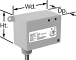
Send a signal to turn equipment on and off from up to 150 feet away without having to run electrical wire. These relays have an enclosure to protect the terminals from dust and accidental bumps. They can be set to transmit, receive, or both at once. You’ll need at least two relays to switch a device. They have an alarm that can be set to check for certain conditions before transmitting a signal. For example, you could set these relays to send a signal to turn on an air conditioner if all windows are closed. The repeat function extends the transmitting signal through a maximum of two receiving relays.
Relays that are set to transmit can be linked up to as many receiving relays as you need. Relays set to receive can be linked up to 30 transmitting relays. All relays connect to dry contacts on your switch, sensor, or controller. Use the wire leads to connect them to a power source.
UL and C-UL listed, all meet American and Canadian safety standards. Rated NEMA 1, they should only be used indoors.
For technical drawings and 3-D models, click on a part number.
Wire Lead | Conduit Connection | |||||||||||||||
|---|---|---|---|---|---|---|---|---|---|---|---|---|---|---|---|---|
| Input Voltage | Control Current | Switching Current @ 277V AC | Maximum Switching Voltage | hp @ Switching Voltage | Ht. | Wd. | Dp. | Maximum Transmission Distance, ft. | Lg. | Number of | Gender | Trade Size | Thread Type | Environmental Rating | Each | |
1 Circuit Controlled with 1 Off (Normally Open) or 1 On (Normally Closed)—SPDT | ||||||||||||||||
| 120V AC | 73 | 20A | 277V AC | 2 hp @ 277 V AC | 2.3" | 3.2" | 1.8" | 150 | 16" | 7 | Male | 1/2 | NPT | NEMA 1 | 0000000 | 0000000 |
| 208V AC | 80 | 20A | 277V AC | 2 hp @ 277 V AC | 2.3" | 3.2" | 1.8" | 150 | 16" | 7 | Male | 1/2 | NPT | NEMA 1 | 0000000 | 000000 |
| 240V AC | 80 | 20A | 277V AC | 2 hp @ 277 V AC | 2.3" | 3.2" | 1.8" | 150 | 16" | 7 | Male | 1/2 | NPT | NEMA 1 | 0000000 | 000000 |
| 277V AC | 80 | 20A | 277V AC | 2 hp @ 277 V AC | 2.3" | 3.2" | 1.8" | 150 | 16" | 7 | Male | 1/2 | NPT | NEMA 1 | 0000000 | 000000 |
| 24V AC, 24V DC | 69 | 20A | 277V AC | 2 hp @ 277 V AC | 2.3" | 3.2" | 1.8" | 150 | 16" | 7 | Male | 1/2 | NPT | NEMA 1 | 0000000 | 000000 |
HDMI Video Cords
Send high-definition signals to monitors, TVs, and projectors.
Cords with a built-in repeater extend the signal to maintain digital quality over long transmission distances.
For technical drawings and 3-D models, click on a part number.
Digital Timers

Timers with a calibration certificate traceable to NIST have been tested to NIST standards to ensure accuracy.
Case | ||||||||||||||
|---|---|---|---|---|---|---|---|---|---|---|---|---|---|---|
| Style | Timing Functions | Max. No. of Events | Max. Timer Duration | Max. Alarm Duration | Resolution | Ht. | Wd. | Dp. | Material | Color | Batteries Included | Features | Each | |
Timers with Calibration Certificate Traceable to NIST | ||||||||||||||
| Y | Count Up Count Down | 1 | 24 hrs. | 1 min. | 1 sec. | 3 1/4" | 2 1/2" | 1/2" | Plastic | White | Yes | Alarm Built-In Stand Memory Function Repeat Function Voice Alerts | 00000000 | 000000 |
Repeat Dispensing Pipettors
Save time dispensing the same amount. Compared to fixed-volume pipettors, these pipettors let you dispense up to 49 samples on a single draw. Set the dispensing volume by turning the adjustment wheel—it’s ribbed, so you can spin it while wearing gloves. A table on the handle shows the adjustment wheel setting for your tip’s capacity and gives you the maximum number of samples for that volume. The dispensing lever is located opposite the finger rest for comfortable use with one hand.
Use with tips for repeat dispensing pipettors. They use a piston to push liquid directly, similar to a syringe, allowing for accurate dispensing. This piston design is ideal for foamy or thick liquids, since other pipettors that push with air may dispense incompletely or cause bubbling. When you’re done, press the ejector button to release the tip without contact.
Capacity | ||||||
|---|---|---|---|---|---|---|
| µL | ml | Overall Lg. | Body Material | Includes | Each | |
| 2 to 5,000 | 0.002 to 5 | 7 1/2" | Polyethylene Plastic | 3 Pipette Tips | 0000000 | 0000000 |
Electronic Repeat Dispensing Pipettors


Dispense multiple samples with a single press of a button. With a capacity 10 times larger than their manual equivalent, these pipettors are a good choice when you need high-volume, precise dispensing. These pipettors are powered by a motor to ensure consistency and prevent fatigue. Program up to 10 frequently used speeds and intervals on the touch screen. Tap and swipe to make adjustments in real time—even while wearing gloves. When not in use, these pipettors rest in their included mounting bracket.
Attach a tip for repeat dispensing pipettors to get started. These tips have a piston that makes direct contact with a sample to reduce bubbles. This makes them a good choice for thick or frothy liquids. Clip on the tip and the pipettor automatically recognizes the tip's capacity. When you're done, tap the eject button to release the tip without contact.
The charging stand (sold separately) starts charging immediately when you hang the pipettor on it, even with the tip still installed. The stand also keeps the pipettor upright between tasks, preventing liquid in the tip from flowing into the pipettor and causing damage. Connect the stand to a wall outlet using your pipettor's included power cord.


