


Filter by

Thread Size
Holding Capacity
Maximum Clamping Clearance

Rotation Direction


Handle Style

Export Control Classification Number (ECCN)
DFARS Specialty Metals
Actuation Type
Direction of Operation
Overall Height
Sensor Ready
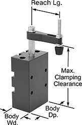
Air-Powered Hold-Down Fixture Clamps for Welding
 |  |
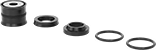
Rubber Holding Screw Tip | Steel Holding Screw Tip |
Extended Clamping Arm | 3 3/4" Lg. Extended Arms |
 | |
Clamping Arm Adapter |
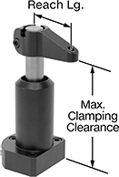
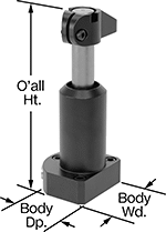
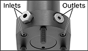
Compact and lightweight, these clamps are easy to move and reposition when welding. Adjust the air pressure to quickly and consistently clamp or release parts. When pressure is applied, the arm on these clamps rotates 90° into position over your workpiece before clamping down. When pressure is released, the arm rises and rotates out of the way, so you can load or unload parts. They’re also known as swing clamps. Attach a sensor (not included) to activate relays and controllers. Connect their ports to a control valve and an air line. Use screws (not included) to mount the base to a flat surface.
All clamps come with a holding screw.
Rubber Holding Screw Tip—Screws with a rubber tip are nonmarring, and their tip is removable.
Replacement Arms—Replacement arms (sold separately) do not include a holding screw. Extended arms (sold separately) give your clamp a longer reach than standard arms. However, you’ll have to use lower pressure, which means the actual clamping force will be lower than the clamp’s listed rating.
Arm Adapters—Add an arm adapter to mount your own custom-machined arm.
Clamps | Replacement Arms | Extended Arms | Arm Adapters | |||||||||||||||||||||||||
|---|---|---|---|---|---|---|---|---|---|---|---|---|---|---|---|---|---|---|---|---|---|---|---|---|---|---|---|---|
Body | Holding Screw | Female Air Inlet and Outlet | Mounting Holes | |||||||||||||||||||||||||
Max. Clamping Clearance | Vert. Travel During Rotation | Max. Clamping Stroke | Holding Cap., lb. | Reach Lg. | Wd. | Dp. | Thread Size | Tip Material | Pipe Size | Thread Size | Thread Type | No. of | Dia. | Thread Size | Dp. | Location | Material | Each | Each | Lg. | Each | Each | ||||||
90° Clockwise Rotation | ||||||||||||||||||||||||||||
| 3 5/8" | 21/32" | 5/16" | 20 | 1 5/8" | 1 1/8" | 1 5/8" | M4 × 0.7 mm | Rubber | — | M5 × 0.8 mm | Metric | 4 2 | — | M5 × 0.8 mm M5 × 0.8 mm | — 9/16" | Side Base | Aluminum | 50185A101 | 0000000 | 50185A105 | 000000 | — | ——— | 0 | 50185A107 | 000000 | ||
| 4 3/8" | 15/32" | 3/8" | 35 | 1 1/8" | 1 1/4" | 1 1/4" | 10-32 | Steel | — | 10-32 | UNF | 4 2 | 3/16" 3/16" | — | — | Side Base | Aluminum | 50185A51 | 000000 | 50185A109 | 00000 | 2 7/8" | 50185A111 | 000000 | 50185A114 | 00000 | ||
| 4 7/8" | 1 3/16" | 9/16" | 100 | 2 9/16" | 2 3/16" | 2 3/4" | M8 × 1.25 mm | Rubber | 1/8 | — | BSPP | 4 4 2 | — | M8 × 1.25 mm M8 × 1.25 mm M8 × 1.25 mm | 3/4" 9/16" 9/16" | Base Side Side | Aluminum | 50185A102 | 000000 | 50185A106 | 00000 | — | ——— | 0 | 50185A108 | 00000 | ||
| 5 1/2" | 3/4" | 1/2" | 130 | 2" | 2" | 3" | 3/8"-16 | Rubber | 1/8 | — | NPT | 4 2 | 11/32" 11/32" | — | — | Side Base | Aluminum | 50185A33 | 000000 | 50185A112 | 00000 | 3 3/4" | 50185A113 | 00000 | 50185A115 | 00000 | ||
90° Counterclockwise Rotation | ||||||||||||||||||||||||||||
| 3 5/8" | 21/32" | 5/16" | 20 | 1 5/8" | 1 1/8" | 1 5/8" | M4 × 0.7 mm | Rubber | — | M5 × 0.8 mm | Metric | 4 2 | — | M5 × 0.8 mm M5 × 0.8 mm | — 9/16" | Side Base | Aluminum | 50185A103 | 000000 | 50185A105 | 00000 | — | ——— | 0 | 50185A107 | 00000 | ||
| 4 3/8" | 15/32" | 3/8" | 35 | 1 1/8" | 1 1/4" | 1 1/4" | 10-32 | Steel | — | 10-32 | UNF | 4 2 | 3/16" 3/16" | — | — | Side Base | Aluminum | 50185A52 | 000000 | 50185A109 | 00000 | 2 7/8" | 50185A111 | 00000 | 50185A114 | 00000 | ||
| 4 7/8" | 1 3/16" | 9/16" | 100 | 2 9/16" | 2 3/16" | 2 3/4" | M8 × 1.25 mm | Rubber | 1/8 | — | BSPP | 4 4 2 | — | M8 × 1.25 mm M8 × 1.25 mm M8 × 1.25 mm | 3/4" 9/16" 9/16" | Base Side Side | Aluminum | 50185A104 | 000000 | 50185A106 | 00000 | — | ——— | 0 | 50185A108 | 00000 | ||
| 5 1/2" | 3/4" | 1/2" | 130 | 2" | 2" | 3" | 3/8"-16 | Rubber | 1/8 | — | NPT | 4 2 | 11/32" 11/32" | — | — | Side Base | Aluminum | 50185A34 | 000000 | 50185A112 | 00000 | 3 3/4" | 50185A113 | 00000 | 50185A115 | 00000 | ||
 |
For Max. Clamping Clearance | Includes | Each | ||
|---|---|---|---|---|
| 4 3/8" | Rod Seal, Rod Wiper, End Cap Seal, Retaining Ring, Aluminum Piston with a Molded Seal and Groove with a Magnetic Ring | 50185A116 | 000000 | |
| 5 1/2" | Rod Seal, Rod Wiper, End Cap Seal, Retaining Ring, Aluminum Piston with a Molded Seal and Groove with a Magnetic Ring | 50185A117 | 00000 |
Rotary Clamping Air Cylinders
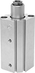 | 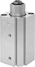 | 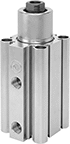 | |
16 mm Bore | 20 mm Bore | 25 mm Bore | 32 mm Bore |
 |  |
16 mm Bore | 20 mm Bore |
| |
25 mm Bore | 32 mm Bore |
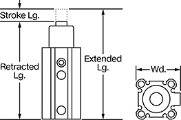
Lg., mm | Air Inlet | 90° Clockwise Shaft Rotation | 90° Counterclockwise Shaft Rotation | |||||||||||||
|---|---|---|---|---|---|---|---|---|---|---|---|---|---|---|---|---|
Stroke | Retracted | Extended | Diag. Wd., mm | Force @ 100 psi, lbf | Body Material | Rod Thread Size | Pipe Size | Thread Size | Thread Type | Gender | Each | Each | ||||
Sensor-Ready Base Mount | ||||||||||||||||
16 mm Bore (29 mm Wide) | ||||||||||||||||
| 20 | 88 | 115 | — | 8 | Aluminum | M5 × 0.8 mm | — | M5 × 0.8 mm | Metric | Female | 6021N11 | 0000000 | 6021N12 | 0000000 | ||
20 mm Bore (36 mm Wide) | ||||||||||||||||
| 10 | 92 | 112 | 47 | 44 | Aluminum | M8 × 1.25 mm | — | M5 × 0.8 mm | Metric | Female | 6021N13 | 000000 | 6021N14 | 000000 | ||
| 20 | 112 | 142 | 47 | 44 | Aluminum | M8 × 1.25 mm | — | M5 × 0.8 mm | Metric | Female | 6021N15 | 000000 | 6021N16 | 000000 | ||
25 mm Bore (40 mm Wide) | ||||||||||||||||
| 10 | 93 | 113 | 52 | 78 | Aluminum | M8 × 1.25 mm | — | M5 × 0.8 mm | Metric | Female | 6021N17 | 000000 | 6021N18 | 000000 | ||
| 20 | 113 | 143 | 52 | 78 | Aluminum | M8 × 1.25 mm | — | M5 × 0.8 mm | Metric | Female | 6021N19 | 000000 | 6021N21 | 000000 | ||
32 mm Bore (49 mm Wide) | ||||||||||||||||
| 10 | 113 | 138 | — | 122 | Aluminum | M10 × 1.5 mm | 1/8 | — | BSPT | Female | 6021N22 | 000000 | 6021N23 | 000000 | ||
| 20 | 133 | 168 | — | 122 | Aluminum | M10 × 1.5 mm | 1/8 | — | BSPT | Female | 6021N24 | 000000 | 6021N25 | 000000 | ||
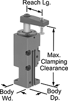
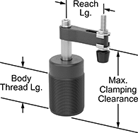
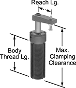
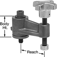
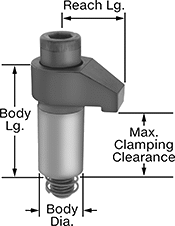
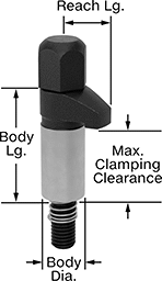
Threaded Air-Powered Hold-Down Fixture Clamps for Welding
 |  |
Rubber Holding Screw Tip | Steel Holding Screw Tip |
| |
Extended Clamping Arm | Clamping Arm Adapter |
Screw these clamps directly into a tapped hole and use air pressure to quickly and consistently clamp and release parts when welding. Compact and lightweight, these clamps are easy to move and reposition when welding. They’re also known as swing clamps. Connect these clamps to a control valve and air line. When pressure is applied, the arm on these clamps rotates 90° into position over your workpiece before clamping down. When pressure is released, the arm rises and rotates out of the way, so you can load or unload parts.
Sensor Ready—Sensor-ready clamps activate relays and controllers when used with a sensor (not included).
Rubber Holding Screw Tip—Clamps with a rubber-tipped holding screw are nonmarring. Their tip is removable.
Replacement Arms—Replacement arms (sold separately) do not include a holding screw. Extended arms (sold separately) give your clamp a longer reach than standard arms. However, you’ll have to use lower pressure, which means the actual clamping force will be lower than the clamp’s listed rating.
Arm Adapters—Add an arm adapter to mount your own custom-machined arm.
Clamps | Replacement Arms | Extended Arms | Arm Adapters | ||||||||||||||||||||||
|---|---|---|---|---|---|---|---|---|---|---|---|---|---|---|---|---|---|---|---|---|---|---|---|---|---|
Body | Holding Screw | Female Air Inlet and Outlet | |||||||||||||||||||||||
Max. Clamping Clearance | Vert. Travel During Rotation | Max. Clamping Stroke | Holding Cap., lb. | Reach Lg. | Thread Size | Thread Lg. | Sensor Ready | Overall Ht. | Thread Size | Tip Material | Pipe Size | Thread Size | Thread Type | Material | Each | Each | Lg. | Each | Each | ||||||
90° Clockwise Rotation | |||||||||||||||||||||||||
| 4" | 1 3/32" | 17/32" | 35 | 1 15/16" | M40 × 1.5 mm | 1 11/16" | Not Sensor Ready | 4 5/8" | M6 × 1 mm | Rubber | — | M5 × 0.8 mm | Metric | Aluminum | 9986N11 | 0000000 | 9986N17 | 000000 | — | ——— | 0 | 9986N18 | 000000 | ||
| 4 3/8" | 15/32" | 3/8" | 35 | 1 1/8" | 1 1/8"-16 | 2 7/8" | Sensor Ready | 4 3/4" | 10-32 | Steel | — | 10-32 | UNF | Aluminum | 50185A18 | 000000 | 50185A109 | 00000 | 2 7/8" | 50185A111 | 000000 | 50185A114 | 00000 | ||
| 4 9/16" | 1 1/8" | 17/32" | 100 | 2 9/16" | M55 × 1.5 mm | 2 1/4" | Not Sensor Ready | 5 1/4" | M8 × 1.25 mm | Rubber | 1/8 | — | BSPP | Aluminum | 9986N12 | 000000 | 50185A106 | 00000 | — | ——— | 0 | 50185A108 | 00000 | ||
| 5 5/16" | 3/4" | 1/2" | 95 | 1 5/8" | 1 3/4"-12 | 3 1/4" | Sensor Ready | 6 1/8" | 3/8"-16 | Rubber | 1/8 | — | NPT | Aluminum | 50185A15 | 000000 | 50185A112 | 00000 | — | ——— | 0 | ——— | 0 | ||
90° Counterclockwise Rotation | |||||||||||||||||||||||||
| 4" | 1 3/32" | 17/32" | 35 | 1 15/16" | M40 × 1.5 mm | 1 11/16" | Not Sensor Ready | 4 5/8" | M6 × 1 mm | Rubber | — | M5 × 0.8 mm | Metric | Aluminum | 9986N13 | 000000 | 9986N17 | 00000 | — | ——— | 0 | 9986N18 | 00000 | ||
| 4 3/8" | 15/32" | 3/8" | 35 | 1 1/8" | 1 1/8"-16 | 2 7/8" | Sensor Ready | 4 3/4" | 10-32 | Steel | — | 10-32 | UNF | Aluminum | 50185A19 | 000000 | 50185A109 | 00000 | 2 7/8" | 50185A111 | 00000 | 50185A114 | 00000 | ||
| 4 9/16" | 1 1/8" | 17/32" | 100 | 2 9/16" | M55 × 1.5 mm | 2 1/4" | Not Sensor Ready | 5 1/4" | M8 × 1.25 mm | Rubber | 1/8 | — | BSPP | Aluminum | 9986N14 | 000000 | 50185A106 | 00000 | — | ——— | 0 | 50185A108 | 00000 | ||
| 5 5/16" | 3/4" | 1/2" | 95 | 1 5/8" | 1 3/4"-12 | 3 1/4" | Sensor Ready | 6 1/8" | 3/8"-16 | Rubber | 1/8 | — | NPT | Aluminum | 50185A16 | 000000 | 50185A112 | 00000 | — | ——— | 0 | ——— | 0 | ||
|
For Max. Clamping Clearance | Includes | Each | ||
|---|---|---|---|---|
| 4 3/8" | Rod Seal, Rod Wiper, End Cap Seal, Retaining Ring, Aluminum Piston with a Molded Seal and Groove with a Magnetic Ring | 50185A116 | 000000 | |
| 5 5/16" | Rod Seal, Rod Wiper, End Cap Seal, Retaining Ring, Aluminum Piston with a Molded Seal and Groove with a Magnetic Ring | 9986N19 | 000000 |
Revolving Screw Clamps
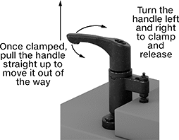
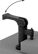
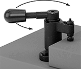
Hold-Down Fixture Clamps with Handle
 |  |
Adjustable Handle | Cam Handle |
 |  |
Lever Handle |
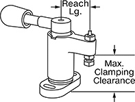
Overall | Mounting Holes | |||||||||||||
|---|---|---|---|---|---|---|---|---|---|---|---|---|---|---|
Max. Clamping Clearance | Max. Clamping Stroke | Holding Cap., lb. | Reach Lg. | Ht. | Wd. | Dp. | Mounting Fasteners Included | No. of | Dia. | Material | Each | |||
Adjustable Handle | ||||||||||||||
70° Clockwise Rotation | ||||||||||||||
| 13/32" | 1/8" | 445 | 7/8" | 2 7/8" | 1 7/16" | 2 5/8" | No | 2 | 5/32" | Black-Oxide Steel | 9963N29 | 0000000 | ||
| 9/16" | 5/32" | 715 | 1 3/16" | 3 7/8" | 1 3/4" | 3 15/16" | No | 2 | 7/32" | Black-Oxide Steel | 9963N32 | 000000 | ||
| 23/32" | 5/32" | 1,000 | 1 7/16" | 4 13/16" | 2 9/16" | 4 15/16" | No | 2 | 5/16" | Black-Oxide Steel | 9963N34 | 000000 | ||
| 7/8" | 3/16" | 1,300 | 1 3/4" | 5 3/4" | 3 3/8" | 5 15/16" | No | 2 | 13/32" | Black-Oxide Steel | 9963N36 | 000000 | ||
70° Counterclockwise Rotation | ||||||||||||||
| 13/32" | 1/8" | 445 | 7/8" | 2 7/8" | 1 7/16" | 2 5/8" | No | 2 | 5/32" | Black-Oxide Steel | 9963N28 | 000000 | ||
| 9/16" | 5/32" | 715 | 1 3/16" | 3 7/8" | 1 3/4" | 3 15/16" | No | 2 | 7/32" | Black-Oxide Steel | 9963N31 | 000000 | ||
| 23/32" | 5/32" | 1,000 | 1 7/16" | 4 13/16" | 2 9/16" | 4 15/16" | No | 2 | 5/16" | Black-Oxide Steel | 9963N33 | 000000 | ||
| 7/8" | 3/16" | 1,300 | 1 3/4" | 5 3/4" | 3 3/8" | 5 15/16" | No | 2 | 13/32" | Black-Oxide Steel | 9963N35 | 000000 | ||
Cam Handle | ||||||||||||||
70° Clockwise Rotation | ||||||||||||||
| 1 3/16" | 1/32" | 175 | 7/8" | 4" | 1 7/16" | 3" | No | 2 | 5/32" | Black-Oxide Steel | 9963N21 | 000000 | ||
| 1 9/16" | 1/32" | 335 | 1 3/16" | 5 3/16" | 1 3/4" | 3 7/8" | No | 2 | 7/32" | Black-Oxide Steel | 9963N23 | 000000 | ||
| 1 15/16" | 3/64" | 470 | 1 7/16" | 6 9/16" | 2 9/16" | 4 15/16" | No | 2 | 5/16" | Black-Oxide Steel | 9963N25 | 000000 | ||
| 2 11/32" | 1/16" | 625 | 1 3/4" | 8 3/16" | 3 3/8" | 6 1/8" | No | 2 | 13/32" | Black-Oxide Steel | 9963N27 | 000000 | ||
70° Counterclockwise Rotation | ||||||||||||||
| 1 3/16" | 1/32" | 175 | 7/8" | 4" | 1 7/16" | 3" | No | 2 | 5/32" | Black-Oxide Steel | 9963N19 | 000000 | ||
| 1 9/16" | 1/32" | 335 | 1 3/16" | 5 3/16" | 1 3/4" | 3 7/8" | No | 2 | 7/32" | Black-Oxide Steel | 9963N22 | 000000 | ||
| 1 15/16" | 3/64" | 470 | 1 7/16" | 6 9/16" | 2 9/16" | 4 15/16" | No | 2 | 5/16" | Black-Oxide Steel | 9963N24 | 000000 | ||
| 2 11/32" | 1/16" | 625 | 1 3/4" | 8 3/16" | 3 3/8" | 6 1/8" | No | 2 | 13/32" | Black-Oxide Steel | 9963N26 | 000000 | ||
Lever Handle | ||||||||||||||
70° Clockwise Rotation | ||||||||||||||
| 1 3/16" | 1/32" | 245 | 7/8" | 1 15/16" | 1 7/16" | 3" | No | 2 | 5/32" | Black-Oxide Steel | 9963N12 | 000000 | ||
| 1 9/16" | 3/64" | 400 | 1 3/16" | 2 5/8" | 1 3/4" | 3 7/8" | No | 2 | 7/32" | Black-Oxide Steel | 9963N14 | 000000 | ||
| 1 15/16" | 1/16" | 490 | 1 7/16" | 3 1/4" | 2 9/16" | 4 15/16" | No | 2 | 5/16" | Black-Oxide Steel | 9963N16 | 000000 | ||
| 2 11/32" | 5/64" | 785 | 1 3/4" | 3 15/16" | 3 3/8" | 6 1/8" | No | 2 | 13/32" | Black-Oxide Steel | 9963N18 | 000000 | ||
70° Counterclockwise Rotation | ||||||||||||||
| 1 3/16" | 1/32" | 245 | 7/8" | 1 15/16" | 1 7/16" | 3" | No | 2 | 5/32" | Black-Oxide Steel | 9963N11 | 000000 | ||
| 1 9/16" | 3/64" | 400 | 1 3/16" | 2 5/8" | 1 3/4" | 3 7/8" | No | 2 | 7/32" | Black-Oxide Steel | 9963N13 | 000000 | ||
| 1 15/16" | 1/16" | 490 | 1 7/16" | 3 1/4" | 2 9/16" | 4 15/16" | No | 2 | 5/16" | Black-Oxide Steel | 9963N15 | 000000 | ||
| 2 11/32" | 5/64" | 785 | 1 3/4" | 3 15/16" | 3 3/8" | 6 1/8" | No | 2 | 13/32" | Black-Oxide Steel | 9963N17 | 000000 | ||
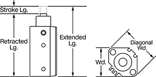
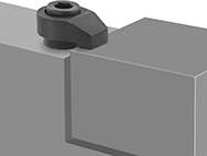
Push Toggle Clamps with Rotating Handle
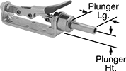 | |
Handle Rotated |
The handle can be rotated 125° for easier access or extra clearance above the clamp. These clamps secure when the plunger is fully extended to hold a workpiece from the side. The plunger is internally threaded to accommodate threaded holding screws and other threaded fixtures (not included).
Hold-Down Fixture Clamps
 |
 |  |  |
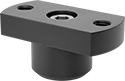
Socket Head Screw | Knob Head Screw with Cap Nut | Mounting Block |
Clamps | Mounts | ||||||||||||||
|---|---|---|---|---|---|---|---|---|---|---|---|---|---|---|---|
Body | Thread | Drive | |||||||||||||
Max. Clamping Clearance | Holding Cap. | Reach Lg. | Lg. | Dia. | Size | Lg. | Size | Style | Material | Each | Each | ||||
Socket Head Screw | |||||||||||||||
| 7/8" | 4,800 lb. | 11/16" | 1 3/8" | 5/8" | 5/16"-18 | 1 3/4" | 1/4" | Hex | Black-Oxide Steel | 8954A11 | 000000 | ——— | 0 | ||
| 29/32" | 2,200 lb. | 1 3/16" | 1 3/8" | 3/4" | 5/16"-18 | 2" | 1/4" | Hex | Black-Oxide Steel | 8954A44 | 00000 | 8954A37 | 000000 | ||
| 1 17/32" | 2,700 lb. | 2 3/8" | 2 1/4" | 1" | 1/2"-13 | 3" | 3/8" | Hex | Black-Oxide Steel | 8954A45 | 00000 | 8954A38 | 00000 | ||
| 1 17/32" | 3,700 lb. | 2 3/8" | 2 3/8" | 1 1/4" | 5/8"-11 | 3 1/4" | 1/2" | Hex | Black-Oxide Steel | 8954A46 | 000000 | 8954A39 | 000000 | ||
| 1 5/8" | 6,400 lb. | 1" | 2 1/4" | 7/8" | 3/8"-16 | 3" | 5/16" | Hex | Black-Oxide Steel | 8954A12 | 00000 | ——— | 0 | ||
| 1 5/8" | 12,000 lb. | 1" | 2 1/4" | 7/8" | 1/2"-13 | 3" | 3/8" | Hex | Black-Oxide Steel | 8954A13 | 00000 | ——— | 0 | ||
| 1 13/16" | 17,000 lb. | 1 7/16" | 2 3/4" | 1 1/8" | 5/8"-11 | 3 1/2" | 1/2" | Hex | Black-Oxide Steel | 8954A15 | 00000 | ——— | 0 | ||
Knob Head Screw with Cap Nut | |||||||||||||||
| 7/8" | Not Rated | 11/16" | 1 3/8" | 5/8" | 5/16"-18 | 2 1/2" | 5/8" | External Hex | Black-Oxide Steel | 8954A111 | 00000 | ——— | 0 | ||
| 1 5/8" | Not Rated | 1" | 2 1/4" | 7/8" | 3/8"-16 | 4" | 3/4" | External Hex | Black-Oxide Steel | 8954A113 | 00000 | ——— | 0 | ||
| 1 5/8" | Not Rated | 1" | 2 1/4" | 7/8" | 1/2"-13 | 4" | 7/8" | External Hex | Black-Oxide Steel | 8954A112 | 00000 | ——— | 0 | ||
Light Duty Fixture Clamp Kits
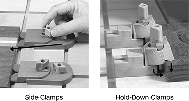 |
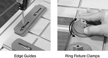 |
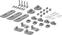 |
No. of Pieces | Includes | Material | Mounting Screw Thread Size | Each | ||
|---|---|---|---|---|---|---|
| 12 | 3 Edge Guides 2 Ring Fixture Clamps 2 Side Clamps 4 Hold-Down Clamps Nylon Mounting Hardware | Plastic | 10-32 | 9896N11 | 0000000 |
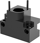
Hydraulic Hold-Down Fixture Clamps
 |
Clamping Arm Shown in Clamping Position (Sold Separately) |
 |  |
Clamping Arm Shown in Open Position (Sold Separately) | Hydraulic Ports |
Best for CNC milling, these clamps combine 10 times the force of air-powered clamps with automated swing action for fast, secure workholding. Their clamping arm (sold separately) rotates up and out of the way when not engaged, so you can easily insert and remove your workpiece.
Connect your hydraulic line to the back or the bottom of the clamp. All ports are sealed with an O-ring and a screw; unseal the port you want to use.
Single Acting—Single-acting clamps only use pressure to clamp down on a workpiece. When you release the pressure, a spring returns the clamping arm to its original position. They’re a good choice for simple setups, where you only need one or two clamps.
Double Acting—Double-acting clamps use pressure both to clamp and release a workpiece, giving you precise control over the process. They’re more efficient than single-acting clamps, since their release is quicker and more predictable. They’re a good choice if you need to coordinate the action of multiple clamps.
Maximum Clamping Stroke—Maximum clamping stroke is the vertical distance a clamping arm can travel to clamp a workpiece.
Arms—Choose an arm best suited for your application. Machinable arms let you customize the length and shape to suit your application. Because they are longer than standard arms, you’ll have to use lower pressure, and their actual clamping force will be lower than the listed rating.
Clamps | Arms | Machinable Arms | |||||||||||||||||||||||
|---|---|---|---|---|---|---|---|---|---|---|---|---|---|---|---|---|---|---|---|---|---|---|---|---|---|
Body | Female Inlet and Outlet | Mounting Holes | |||||||||||||||||||||||
Max. Clamping Clearance | Vert. Travel During Rotation | Max. Clamping Stroke | Overall Ht. | Wd. | Dp. | Thread Type | Thread Size | Max. Clamping Force, lbf | Mounting Fasteners Included | No. of | Thread Size | Dp. | Location | Material | Each | Lg. | Reach Lg. | Each | Lg. | Each | |||||
Single Acting | |||||||||||||||||||||||||
90° Clockwise Rotation | |||||||||||||||||||||||||
| 4 9/16" | 1/2" | 3/8" | 5 5/16" | 2 1/4" | 2 1/8" | UN/UNF (SAE Straight) | 7/16"-20 | 1,100 | Yes | 3 | 1/4"-28 | 5/8" | Lower Flange | Steel | 9964N101 | 0000000 | 2 5/8" | 1 9/16" | 9964N114 | 000000 | 5 13/16" | 9964N117 | 0000000 | ||
| 5 9/16" | 19/32" | 1/2" | 6 3/4" | 2 7/8" | 2 5/8" | UN/UNF (SAE Straight) | 7/16"-20 | 2,400 | Yes | 3 | 5/16"-24 | 13/16" | Lower Flange | Steel | 9964N102 | 000000 | 3 3/8" | 2" | 9964N115 | 000000 | 7 1/16" | 9964N118 | 000000 | ||
| 6 3/16" | 21/32" | 5/8" | 8 7/8" | 3 1/2" | 3 15/16" | UN/UNF (SAE Straight) | 7/16"-20 | 7,450 | Yes | 4 | 3/8"-24 | 3/4" | Lower Flange | Steel | 9964N103 | 00000000 | 4 3/4" | 2 11/16" | 9964N116 | 000000 | 8 1/2" | 9964N119 | 000000 | ||
90° Counterclockwise Rotation | |||||||||||||||||||||||||
| 4 9/16" | 1/2" | 3/8" | 5 5/16" | 2 1/4" | 2 1/8" | UN/UNF (SAE Straight) | 7/16"-20 | 1,100 | Yes | 3 | 1/4"-28 | 5/8" | Lower Flange | Steel | 9964N107 | 000000 | 2 5/8" | 1 9/16" | 9964N114 | 00000 | 5 13/16" | 9964N117 | 000000 | ||
| 5 9/16" | 19/32" | 1/2" | 6 3/4" | 2 7/8" | 2 5/8" | UN/UNF (SAE Straight) | 7/16"-20 | 2,400 | Yes | 3 | 5/16"-24 | 13/16" | Lower Flange | Steel | 9964N108 | 000000 | 3 3/8" | 2" | 9964N115 | 000000 | 7 1/16" | 9964N118 | 000000 | ||
| 6 3/16" | 21/32" | 5/8" | 8 7/8" | 3 1/2" | 3 15/16" | UN/UNF (SAE Straight) | 7/16"-20 | 7,450 | Yes | 4 | 3/8"-24 | 3/4" | Lower Flange | Steel | 9964N109 | 00000000 | 4 3/4" | 2 11/16" | 9964N116 | 000000 | 8 1/2" | 9964N119 | 000000 | ||
Double Acting | |||||||||||||||||||||||||
90° Clockwise Rotation | |||||||||||||||||||||||||
| 4 9/16" | 1/2" | 3/8" | 5 5/16" | 2 1/4" | 2 1/8" | UN/UNF (SAE Straight) | 7/16"-20 | 1,250 | Yes | 3 | 1/4"-28 | 5/8" | Lower Flange | Steel | 9964N104 | 000000 | 2 5/8" | 1 9/16" | 9964N114 | 00000 | 5 13/16" | 9964N117 | 000000 | ||
| 5 9/16" | 19/32" | 1/2" | 6 3/4" | 2 7/8" | 2 5/8" | UN/UNF (SAE Straight) | 7/16"-20 | 2,600 | Yes | 3 | 5/16"-24 | 13/16" | Lower Flange | Steel | 9964N105 | 000000 | 3 3/8" | 2" | 9964N115 | 000000 | 7 1/16" | 9964N118 | 000000 | ||
| 6 3/16" | 21/32" | 5/8" | 7 3/4" | 3 1/2" | 3 15/16" | UN/UNF (SAE Straight) | 7/16"-20 | 7,600 | Yes | 4 | 3/8"-24 | 3/4" | Lower Flange | Steel | 9964N106 | 00000000 | 4 3/4" | 2 11/16" | 9964N116 | 000000 | 8 1/2" | 9964N119 | 000000 | ||
90° Counterclockwise Rotation | |||||||||||||||||||||||||
| 4 9/16" | 1/2" | 3/8" | 5 5/16" | 2 1/4" | 2 1/8" | UN/UNF (SAE Straight) | 7/16"-20 | 1,250 | Yes | 3 | 1/4"-28 | 5/8" | Lower Flange | Steel | 9964N111 | 000000 | 2 5/8" | 1 9/16" | 9964N114 | 00000 | 5 13/16" | 9964N117 | 000000 | ||
| 5 9/16" | 19/32" | 1/2" | 6 3/4" | 2 7/8" | 2 5/8" | UN/UNF (SAE Straight) | 7/16"-20 | 2,600 | Yes | 3 | 5/16"-24 | 13/16" | Lower Flange | Steel | 9964N112 | 000000 | 3 3/8" | 2" | 9964N115 | 000000 | 7 1/16" | 9964N118 | 000000 | ||
| 6 3/16" | 21/32" | 5/8" | 7 3/4" | 3 1/2" | 3 15/16" | UN/UNF (SAE Straight) | 7/16"-20 | 7,600 | Yes | 4 | 3/8"-24 | 3/4" | Lower Flange | Steel | 9964N113 | 00000000 | 4 3/4" | 2 11/16" | 9964N116 | 000000 | 8 1/2" | 9964N119 | 000000 | ||
