


Filter by
Shaft Diameter
Material
Construction
Overall Length
Shaft Mount Type

OD

For Shaft Misalignment Type
For Rotary Motion

Length
Clamping Screw Material
Maximum Torque
DFARS Specialty Metals
Export Control Classification Number (ECCN)
Torque
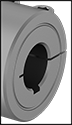
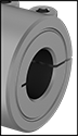
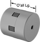
Machinable-Bore Clamping Rigid Shaft Couplings
Steel
 |  |  |
For Keyed Shafts | For Round Shafts |
Steel couplings resist corrosion in dry environments.
For Keyed Shafts—Couplings for keyed shafts grip the shaft’s key to eliminate slipping. They handle higher torque than couplings for round shafts.
For Shaft Dia. | Overall Lg. | OD | Max. Rotation Speed | Max. Torque, in·lbf | For Rotary Motion | Each | |||
|---|---|---|---|---|---|---|---|---|---|
For Keyed Shafts | |||||||||
| 1/2" × 0.235" to 0.500" | 1 7/8" | 1 1/4" | Not Rated | 380 | Forward/Reverse, Start/Stop, Continuous | 3084K65 | 000000 | ||
| 5/8" × 0.235" to 0.625" | 2 1/4" | 1 1/2" | Not Rated | 785 | Forward/Reverse, Start/Stop, Continuous | 3084K66 | 00000 | ||
| 3/4" × 0.235" to 0.750" | 2 5/8" | 1 3/4" | Not Rated | 1,505 | Forward/Reverse, Start/Stop, Continuous | 3084K67 | 00000 | ||
| 7/8" × 0.235" to 0.875" | 2 7/8" | 1 7/8" | Not Rated | 1,760 | Forward/Reverse, Start/Stop, Continuous | 3084K68 | 00000 | ||
| 1" × 0.360" to 1.000" | 3" | 2" | Not Rated | 2,010 | Forward/Reverse, Start/Stop, Continuous | 3084K69 | 00000 | ||
| 1 1/8" × 0.360" to 1.125" | 3 1/4" | 2 1/8" | Not Rated | 2,260 | Forward/Reverse, Start/Stop, Continuous | 3084K71 | 00000 | ||
| 1 1/4" × 0.360" to 1.250" | 3 3/8" | 2 1/4" | Not Rated | 2,510 | Forward/Reverse, Start/Stop, Continuous | 3084K72 | 00000 | ||
| 1 3/8" × 0.360" to 1.375" | 3 5/8" | 2 3/8" | Not Rated | 2,770 | Forward/Reverse, Start/Stop, Continuous | 3084K73 | 00000 | ||
| 1 1/2" × 0.485" to 1.500" | 3 3/4" | 2 1/2" | Not Rated | 3,020 | Forward/Reverse, Start/Stop, Continuous | 3084K74 | 000000 | ||
| 1 3/4" × 0.485" to 1.750" | 4 1/2" | 3" | Not Rated | 5,625 | Forward/Reverse, Start/Stop, Continuous | 3084K75 | 000000 | ||
| 2" × 0.485" to 2.000" | 4 7/8" | 3 1/4" | Not Rated | 6,430 | Forward/Reverse, Start/Stop, Continuous | 3084K76 | 000000 | ||
| 8 mm × 6.000 mm to 8.000 mm | 30 mm | 18 mm | Not Rated | 225 | Forward/Reverse, Start/Stop, Continuous | 3084K114 | 00000 | ||
| 10 mm × 6.000 mm to 10.000 mm | 35 mm | 24 mm | Not Rated | 285 | Forward/Reverse, Start/Stop, Continuous | 3084K115 | 00000 | ||
| 12 mm × 6.000 mm to 12.000 mm | 45 mm | 28 mm | Not Rated | 545 | Forward/Reverse, Start/Stop, Continuous | 3084K116 | 00000 | ||
| 16 mm × 6.000 mm to 16.000 mm | 50 mm | 34 mm | Not Rated | 1,095 | Forward/Reverse, Start/Stop, Continuous | 3084K117 | 00000 | ||
| 20 mm × 6.000 mm to 20.000 mm | 65 mm | 40 mm | Not Rated | 2,025 | Forward/Reverse, Start/Stop, Continuous | 3084K118 | 00000 | ||
| 25 mm × 9.500 mm to 25.000 mm | 65 mm | 45 mm | Not Rated | 2,535 | Forward/Reverse, Start/Stop, Continuous | 3084K119 | 00000 | ||
| 30 mm × 9.500 mm to 30.000 mm | 75 mm | 54 mm | Not Rated | 5,420 | Forward/Reverse, Start/Stop, Continuous | 3084K121 | 000000 | ||
| 35 mm × 9.500 mm to 35.000 mm | 80 mm | 57 mm | Not Rated | 3,550 | Forward/Reverse, Start/Stop, Continuous | 3084K122 | 000000 | ||
| 40 mm × 12.500 mm to 40.000 mm | 90 mm | 60 mm | Not Rated | 4,055 | Forward/Reverse, Start/Stop, Continuous | 3084K123 | 000000 | ||
For Round Shafts | |||||||||
| 1/2" × 0.235" to 0.500" | 1 7/8" | 1 1/4" | Not Rated | 285 | Forward/Reverse, Start/Stop, Continuous | 3084K31 | 00000 | ||
| 5/8" × 0.235" to 0.625" | 2 1/4" | 1 1/2" | Not Rated | 490 | Forward/Reverse, Start/Stop, Continuous | 3084K32 | 00000 | ||
| 3/4" × 0.235" to 0.750" | 2 5/8" | 1 3/4" | Not Rated | 1,130 | Forward/Reverse, Start/Stop, Continuous | 3084K33 | 00000 | ||
| 7/8" × 0.235" to 0.875" | 2 7/8" | 1 7/8" | Not Rated | 1,320 | Forward/Reverse, Start/Stop, Continuous | 3084K47 | 00000 | ||
| 1" × 0.360" to 1.000" | 3" | 2" | Not Rated | 1,510 | Forward/Reverse, Start/Stop, Continuous | 3084K34 | 00000 | ||
| 1 1/8" × 0.360" to 1.125" | 3 1/4" | 2 1/8" | Not Rated | 1,695 | Forward/Reverse, Start/Stop, Continuous | 3084K48 | 00000 | ||
| 1 1/4" × 0.360" to 1.250" | 3 3/8" | 2 1/4" | Not Rated | 1,885 | Forward/Reverse, Start/Stop, Continuous | 3084K35 | 00000 | ||
| 1 3/8" × 0.360" to 1.375" | 3 5/8" | 2 3/8" | Not Rated | 2,080 | Forward/Reverse, Start/Stop, Continuous | 3084K49 | 00000 | ||
| 1 1/2" × 0.485" to 1.500" | 3 3/4" | 2 1/2" | Not Rated | 2,265 | Forward/Reverse, Start/Stop, Continuous | 3084K36 | 00000 | ||
| 1 3/4" × 0.485" to 1.750" | 4 1/2" | 3" | Not Rated | 4,220 | Forward/Reverse, Start/Stop, Continuous | 3084K51 | 000000 | ||
| 2" × 0.485" to 2.000" | 4 7/8" | 3 1/4" | Not Rated | 4,825 | Forward/Reverse, Start/Stop, Continuous | 3084K52 | 000000 | ||
| 8 mm × 6.000 mm to 8.000 mm | 30 mm | 18 mm | Not Rated | 170 | Forward/Reverse, Start/Stop, Continuous | 3084K89 | 00000 | ||
| 10 mm × 6.000 mm to 10.000 mm | 35 mm | 24 mm | Not Rated | 210 | Forward/Reverse, Start/Stop, Continuous | 3084K91 | 00000 | ||
| 12 mm × 6.000 mm to 12.000 mm | 45 mm | 28 mm | Not Rated | 405 | Forward/Reverse, Start/Stop, Continuous | 3084K92 | 00000 | ||
| 16 mm × 6.000 mm to 16.000 mm | 50 mm | 34 mm | Not Rated | 820 | Forward/Reverse, Start/Stop, Continuous | 3084K93 | 00000 | ||
| 20 mm × 6.000 mm to 20.000 mm | 65 mm | 40 mm | Not Rated | 1,520 | Forward/Reverse, Start/Stop, Continuous | 3084K94 | 00000 | ||
| 25 mm × 9.500 mm to 25.000 mm | 65 mm | 45 mm | Not Rated | 1,900 | Forward/Reverse, Start/Stop, Continuous | 3084K95 | 00000 | ||
| 30 mm × 9.500 mm to 30.000 mm | 75 mm | 54 mm | Not Rated | 4,065 | Forward/Reverse, Start/Stop, Continuous | 3084K96 | 00000 | ||
| 35 mm × 9.500 mm to 35.000 mm | 80 mm | 57 mm | Not Rated | 2,660 | Forward/Reverse, Start/Stop, Continuous | 3084K97 | 000000 | ||
| 40 mm × 12.500 mm to 40.000 mm | 90 mm | 60 mm | Not Rated | 3,040 | Forward/Reverse, Start/Stop, Continuous | 3084K98 | 000000 | ||
303 Stainless Steel
| | |
For Keyed Shafts | For Round Shafts |
303 stainless steel couplings resist rusting from water. But, they won’t stand up to salt water or chloride.
For Keyed Shafts—Couplings for keyed shafts grip the shaft’s key to eliminate slipping. They handle higher torque than couplings for round shafts.
For Shaft Dia. | Overall Lg. | OD | Max. Rotation Speed | Max. Torque, in·lbf | For Rotary Motion | Each | |||
|---|---|---|---|---|---|---|---|---|---|
For Keyed Shafts | |||||||||
| 1/2" × 0.235" to 0.500" | 1 7/8" | 1 1/4" | Not Rated | 260 | Forward/Reverse, Start/Stop, Continuous | 3084K77 | 000000 | ||
| 5/8" × 0.235" to 0.625" | 2 1/4" | 1 1/2" | Not Rated | 540 | Forward/Reverse, Start/Stop, Continuous | 3084K78 | 000000 | ||
| 3/4" × 0.235" to 0.750" | 2 5/8" | 1 3/4" | Not Rated | 1,035 | Forward/Reverse, Start/Stop, Continuous | 3084K79 | 000000 | ||
| 1" × 0.360" to 1.000" | 3" | 2" | Not Rated | 1,380 | Forward/Reverse, Start/Stop, Continuous | 3084K82 | 000000 | ||
| 1 1/8" × 0.360" to 1.125" | 3 1/4" | 2 1/8" | Not Rated | 1,550 | Forward/Reverse, Start/Stop, Continuous | 3084K83 | 000000 | ||
| 1 1/4" × 0.360" to 1.250" | 3 3/8" | 2 1/4" | Not Rated | 1,725 | Forward/Reverse, Start/Stop, Continuous | 3084K84 | 000000 | ||
| 1 1/2" × 0.485" to 1.500" | 3 3/4" | 2 1/2" | Not Rated | 2,075 | Forward/Reverse, Start/Stop, Continuous | 3084K86 | 000000 | ||
| 10 mm × 6.000 mm to 10.000 mm | 35 mm | 24 mm | Not Rated | 65 | Forward/Reverse, Start/Stop, Continuous | 3084K127 | 00000 | ||
| 12 mm × 6.000 mm to 12.000 mm | 45 mm | 28 mm | Not Rated | 240 | Forward/Reverse, Start/Stop, Continuous | 3084K128 | 00000 | ||
| 16 mm × 6.000 mm to 16.000 mm | 50 mm | 34 mm | Not Rated | 485 | Forward/Reverse, Start/Stop, Continuous | 3084K129 | 00000 | ||
| 20 mm × 6.000 mm to 20.000 mm | 65 mm | 40 mm | Not Rated | 900 | Forward/Reverse, Start/Stop, Continuous | 3084K131 | 000000 | ||
For Round Shafts | |||||||||
| 1/2" × 0.235" to 0.500" | 1 7/8" | 1 1/4" | Not Rated | 195 | Forward/Reverse, Start/Stop, Continuous | 3084K53 | 00000 | ||
| 5/8" × 0.235" to 0.625" | 2 1/4" | 1 1/2" | Not Rated | 405 | Forward/Reverse, Start/Stop, Continuous | 3084K54 | 00000 | ||
| 3/4" × 0.235" to 0.750" | 2 5/8" | 1 3/4" | Not Rated | 775 | Forward/Reverse, Start/Stop, Continuous | 3084K55 | 00000 | ||
| 7/8" × 0.235" to 0.875" | 2 7/8" | 1 7/8" | Not Rated | 905 | Forward/Reverse, Start/Stop, Continuous | 3084K56 | 000000 | ||
| 1" × 0.360" to 1.000" | 3" | 2" | Not Rated | 1,035 | Forward/Reverse, Start/Stop, Continuous | 3084K57 | 000000 | ||
| 1 1/4" × 0.360" to 1.250" | 3 3/8" | 2 1/4" | Not Rated | 1,295 | Forward/Reverse, Start/Stop, Continuous | 3084K59 | 000000 | ||
| 1 1/2" × 0.485" to 1.500" | 3 3/4" | 2 1/2" | Not Rated | 1,555 | Forward/Reverse, Start/Stop, Continuous | 3084K62 | 000000 | ||
| 1 3/4" × 0.485" to 1.750" | 4 1/2" | 3" | Not Rated | 2,900 | Forward/Reverse, Start/Stop, Continuous | 3084K63 | 000000 | ||
| 8 mm × 6.000 mm to 8.000 mm | 30 mm | 18 mm | Not Rated | 35 | Forward/Reverse, Start/Stop, Continuous | 3084K102 | 00000 | ||
| 10 mm × 6.000 mm to 10.000 mm | 35 mm | 24 mm | Not Rated | 45 | Forward/Reverse, Start/Stop, Continuous | 3084K103 | 00000 | ||
| 12 mm × 6.000 mm to 12.000 mm | 45 mm | 28 mm | Not Rated | 180 | Forward/Reverse, Start/Stop, Continuous | 3084K104 | 00000 | ||
| 16 mm × 6.000 mm to 16.000 mm | 50 mm | 34 mm | Not Rated | 365 | Forward/Reverse, Start/Stop, Continuous | 3084K105 | 000000 | ||
| 20 mm × 6.000 mm to 20.000 mm | 65 mm | 40 mm | Not Rated | 675 | Forward/Reverse, Start/Stop, Continuous | 3084K106 | 000000 | ||
Machinable Shaft Ends
Straight End
 |
 |
 |  |
For Keyed Shafts | For Round Shafts |
For Shaft Dia. | Overall Lg. | OD | For Rotary Motion | Each | |||
|---|---|---|---|---|---|---|---|
Black-Oxide 1215 Carbon Steel | |||||||
For Keyed Shafts | |||||||
| 1/2" | 2 3/4" | 1 1/4" | Continuous, Forward/Reverse, Start/Stop | 3463N75 | 000000 | ||
| 5/8" | 3 1/4" | 1 1/2" | Continuous, Forward/Reverse, Start/Stop | 3463N76 | 00000 | ||
| 3/4" | 4 1/4" | 1 3/4" | Continuous, Forward/Reverse, Start/Stop | 3463N77 | 00000 | ||
| 7/8" | 4 3/8" | 1 7/8" | Continuous, Forward/Reverse, Start/Stop | 3463N78 | 00000 | ||
| 1" | 4 3/4" | 2" | Continuous, Forward/Reverse, Start/Stop | 3463N79 | 00000 | ||
| 1 1/8" | 4 3/4" | 2 1/8" | Continuous, Forward/Reverse, Start/Stop | 3463N81 | 00000 | ||
| 1 1/4" | 5" | 2 1/4" | Continuous, Forward/Reverse, Start/Stop | 3463N82 | 000000 | ||
| 1 3/8" | 5" | 2 3/8" | Continuous, Forward/Reverse, Start/Stop | 3463N83 | 000000 | ||
| 1 1/2" | 5 3/8" | 2 1/2" | Continuous, Forward/Reverse, Start/Stop | 3463N84 | 000000 | ||
| 1 3/4" | 6" | 3" | Continuous, Forward/Reverse, Start/Stop | 3463N85 | 000000 | ||
| 2" | 6 3/4" | 3 1/4" | Continuous, Forward/Reverse, Start/Stop | 3463N86 | 000000 | ||
For Round Shafts | |||||||
| 1/2" | 2 3/4" | 1 1/4" | Continuous, Forward/Reverse, Start/Stop | 3463N51 | 00000 | ||
| 5/8" | 3 1/4" | 1 1/2" | Continuous, Forward/Reverse, Start/Stop | 3463N52 | 00000 | ||
| 3/4" | 4 1/4" | 1 3/4" | Continuous, Forward/Reverse, Start/Stop | 3463N53 | 00000 | ||
| 7/8" | 4 3/8" | 1 7/8" | Continuous, Forward/Reverse, Start/Stop | 3463N54 | 00000 | ||
| 1" | 4 3/4" | 2" | Continuous, Forward/Reverse, Start/Stop | 3463N55 | 00000 | ||
| 1 1/8" | 4 3/4" | 2 1/8" | Continuous, Forward/Reverse, Start/Stop | 3463N56 | 00000 | ||
| 1 1/4" | 5" | 2 1/4" | Continuous, Forward/Reverse, Start/Stop | 3463N57 | 00000 | ||
| 1 3/8" | 5" | 2 3/8" | Continuous, Forward/Reverse, Start/Stop | 3463N58 | 00000 | ||
| 1 1/2" | 5 3/8" | 2 1/2" | Continuous, Forward/Reverse, Start/Stop | 3463N59 | 00000 | ||
| 1 3/4" | 6" | 3" | Continuous, Forward/Reverse, Start/Stop | 3463N61 | 000000 | ||
| 2" | 6 3/4" | 3 1/4" | Continuous, Forward/Reverse, Start/Stop | 3463N62 | 000000 | ||
303 Stainless Steel | |||||||
For Keyed Shafts | |||||||
| 1/2" | 2 3/4" | 1 1/4" | Continuous, Forward/Reverse, Start/Stop | 3463N87 | 00000 | ||
| 5/8" | 3 1/4" | 1 1/2" | Continuous, Forward/Reverse, Start/Stop | 3463N88 | 00000 | ||
| 3/4" | 4 1/4" | 1 3/4" | Continuous, Forward/Reverse, Start/Stop | 3463N89 | 000000 | ||
| 7/8" | 4 3/8" | 1 7/8" | Continuous, Forward/Reverse, Start/Stop | 3463N91 | 000000 | ||
| 1" | 4 3/4" | 2" | Continuous, Forward/Reverse, Start/Stop | 3463N92 | 000000 | ||
| 1 1/8" | 4 3/4" | 2 1/8" | Continuous, Forward/Reverse, Start/Stop | 3463N93 | 000000 | ||
| 1 1/4" | 5" | 2 1/4" | Continuous, Forward/Reverse, Start/Stop | 3463N94 | 000000 | ||
| 1 3/8" | 5" | 2 3/8" | Continuous, Forward/Reverse, Start/Stop | 3463N95 | 000000 | ||
| 1 1/2" | 5 3/8" | 2 1/2" | Continuous, Forward/Reverse, Start/Stop | 3463N96 | 000000 | ||
| 1 3/4" | 6" | 3" | Continuous, Forward/Reverse, Start/Stop | 3463N97 | 000000 | ||
| 2" | 6 3/4" | 3 1/4" | Continuous, Forward/Reverse, Start/Stop | 3463N98 | 000000 | ||
For Round Shafts | |||||||
| 1/2" | 2 3/4" | 1 1/4" | Continuous, Forward/Reverse, Start/Stop | 3463N63 | 00000 | ||
| 5/8" | 3 1/4" | 1 1/2" | Continuous, Forward/Reverse, Start/Stop | 3463N64 | 00000 | ||
| 3/4" | 4 1/4" | 1 3/4" | Continuous, Forward/Reverse, Start/Stop | 3463N65 | 00000 | ||
| 7/8" | 4 3/8" | 1 7/8" | Continuous, Forward/Reverse, Start/Stop | 3463N66 | 00000 | ||
| 1" | 4 3/4" | 2" | Continuous, Forward/Reverse, Start/Stop | 3463N67 | 000000 | ||
| 1 1/8" | 4 3/4" | 2 1/8" | Continuous, Forward/Reverse, Start/Stop | 3463N68 | 00000 | ||
| 1 1/4" | 5" | 2 1/4" | Continuous, Forward/Reverse, Start/Stop | 3463N69 | 000000 | ||
| 1 3/8" | 5" | 2 3/8" | Continuous, Forward/Reverse, Start/Stop | 3463N71 | 000000 | ||
| 1 1/2" | 5 3/8" | 2 1/2" | Continuous, Forward/Reverse, Start/Stop | 3463N72 | 000000 | ||
| 1 3/4" | 6" | 3" | Continuous, Forward/Reverse, Start/Stop | 3463N73 | 000000 | ||
| 2" | 6 3/4" | 3 1/4" | Continuous, Forward/Reverse, Start/Stop | 3463N74 | 000000 | ||
Flanged End
 |
| |
For Keyed Shafts | For Round Shafts |
For Shaft Dia. | Overall Lg. | OD | Flange OD | For Rotary Motion | Each | |||
|---|---|---|---|---|---|---|---|---|
Black-Oxide 1117 Carbon Steel | ||||||||
For Keyed Shafts | ||||||||
| 1/2" | 1 11/16" | 1 1/4" | 2 15/64" | Continuous, Forward/Reverse, Start/Stop | 3463N31 | 000000 | ||
| 3/4" | 2 1/16" | 1 3/4" | 2 63/64" | Continuous, Forward/Reverse, Start/Stop | 3463N32 | 000000 | ||
| 1" | 2 1/4" | 2" | 3 15/64" | Continuous, Forward/Reverse, Start/Stop | 3463N33 | 000000 | ||
For Round Shafts | ||||||||
| 1/2" | 1 11/16" | 1 1/4" | 2 15/64" | Continuous, Forward/Reverse, Start/Stop | 3463N11 | 00000 | ||
| 3/4" | 2 1/16" | 1 3/4" | 2 63/64" | Continuous, Forward/Reverse, Start/Stop | 3463N12 | 00000 | ||
| 1" | 2 1/4" | 2" | 3 15/64" | Continuous, Forward/Reverse, Start/Stop | 3463N13 | 00000 | ||
303 Stainless Steel | ||||||||
For Keyed Shafts | ||||||||
| 1/2" | 1 11/16" | 1 1/4" | 2 15/64" | Continuous, Forward/Reverse, Start/Stop | 3463N41 | 000000 | ||
| 3/4" | 2 1/16" | 1 3/4" | 2 63/64" | Continuous, Forward/Reverse, Start/Stop | 3463N42 | 000000 | ||
| 1" | 2 1/4" | 2" | 3 15/64" | Continuous, Forward/Reverse, Start/Stop | 3463N43 | 000000 | ||
For Round Shafts | ||||||||
| 1/2" | 1 11/16" | 1 1/4" | 2 15/64" | Continuous, Forward/Reverse, Start/Stop | 3463N21 | 00000 | ||
| 3/4" | 2 1/16" | 1 3/4" | 2 63/64" | Continuous, Forward/Reverse, Start/Stop | 3463N22 | 000000 | ||
| 1" | 2 1/4" | 2" | 3 15/64" | Continuous, Forward/Reverse, Start/Stop | 3463N23 | 000000 | ||
Machinable-Bore Flexible Shaft Couplings
 | 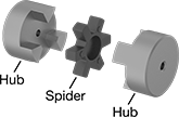 |
(Each Component Sold Separately) |
Customize the bore of these flexible couplings to align uncommon shaft sizes as well as shafts that have become undersized from wear or oversized from coatings. Also known as Lovejoy® couplings, these three-piece couplings have a spider-shaped cushion between two hubs to reduce shock and handle minor shaft misalignment. A complete coupling consists of two hubs and one spider (all components sold separately). Fasten to your shaft with set screws (not included), which bite into the shaft for a secure hold. If the spider fails, the hubs will lock together, giving you time to shut down your equipment to prevent component damage and replace the spider. These couplings do not need lubrication.
Iron Hubs and Buna-N Spiders
Hubs | Buna-N Spiders | ||||||||||||||||
|---|---|---|---|---|---|---|---|---|---|---|---|---|---|---|---|---|---|
For Set Screw | Misalignment Capability | ||||||||||||||||
For Shaft Dia. | Overall Lg. | OD | For Rotary Motion | Fabrication | Type | Thread Size | Each | Max. Rotation Speed, rpm | Max. Torque, in·lbf | Parallel | Angular | Temp. Range, ° F | Spider Material | Each | |||
| 1/4" to 5/8" | 1 23/32" | 1 5/64" | Forward/Reverse, Start/Stop | Sintered | Cup Point | 1/4"-20 | 3530N111 | 00000 | 18,000 | 26 | 0.015" | 1° | -40 to 212 | Buna-N | 6408K84 | 00000 | |
| 1/4" to 3/4" | 1 63/64" | 1 23/64" | Forward/Reverse, Start/Stop | Sintered | Cup Point | 1/4"-20 | 3530N112 | 00000 | 14,000 | 43 | 0.015" | 1° | -40 to 212 | Buna-N | 6408K73 | 0000 | |
| 1/4" to 7/8" | 2 1/8" | 1 3/4" | Forward/Reverse, Start/Stop | Sintered | Cup Point | 1/4"-20 | 3530N113 | 00000 | 11,000 | 90 | 0.015" | 1° | -40 to 212 | Buna-N | 6408K74 | 00000 | |
| 1/4" to 1" | 2 5/32" | 2 7/64" | Forward/Reverse, Start/Stop | Sintered | Cup Point | 1/4"-20 | 3530N114 | 00000 | 9,000 | 140 | 0.015" | 1° | -40 to 212 | Buna-N | 6408K75 | 00000 | |
| 7/16" to 1 1/8" | 2 1/2" | 2 7/64" | Forward/Reverse, Start/Stop | Sintered | Cup Point | 5/16"-18 | 3530N115 | 00000 | 9,000 | 140 | 0.015" | 1° | -40 to 212 | Buna-N | 6408K75 | 00000 | |
| 7/16" to 1 3/16" | 2 27/32" | 2 35/64" | Forward/Reverse, Start/Stop | Sintered | Cup Point | 5/16"-18 | 3530N116 | 00000 | 7,000 | 315 | 0.015" | 1° | -40 to 212 | Buna-N | 6408K77 | 00000 | |
| 7/16" to 1 3/8" | 3 31/64" | 2 35/64" | Forward/Reverse, Start/Stop | Sintered | Cup Point | 5/16"-18 | 3530N117 | 00000 | 7,000 | 315 | 0.015" | 1° | -40 to 212 | Buna-N | 6408K77 | 00000 | |
| 5/8" to 1 5/8" | 4 7/32" | 3 21/64" | Forward/Reverse, Start/Stop | Sintered | Cup Point | 5/16"-18 | 3530N118 | 00000 | 5,000 | 790 | 0.015" | 1° | -40 to 212 | Buna-N | 6408K79 | 00000 | |
| 5/8" to 1 7/8" | 4 1/2" | 3 3/4" | Forward/Reverse, Start/Stop | Sintered | Cup Point | 3/8"-16 | 3530N119 | 000000 | 5,000 | 1,240 | 0.015" | 1° | -40 to 212 | Buna-N | 6408K81 | 00000 | |
| 3/4" to 2 1/8" | 4 7/8" | 4 1/2" | Forward/Reverse, Start/Stop | Sintered | Cup Point | 1/2"-13 | 3530N121 | 000000 | 5,000 | 1,725 | 0.015" | 1° | -40 to 212 | Buna-N | 6408K82 | 00000 | |
| 3/4" to 2 5/8" | 5 11/32" | 5" | Forward/Reverse, Start/Stop | Cast | Cup Point | 1/2"-13 | 3530N122 | 000000 | 4,200 | 2,340 | 0.015" | 1° | -40 to 212 | Buna-N | 6408K62 | 00000 | |
Iron Hubs and Polyurethane Spiders
Hubs | Polyurethane Spiders | ||||||||||||||||
|---|---|---|---|---|---|---|---|---|---|---|---|---|---|---|---|---|---|
For Set Screw | Misalignment Capability | ||||||||||||||||
For Shaft Dia. | Overall Lg. | OD | For Rotary Motion | Fabrication | Type | Thread Size | Each | Max. Rotation Speed, rpm | Max. Torque, in·lbf | Parallel | Angular | Temp. Range, ° F | Spider Material | Each | |||
| 1/4" to 7/8" | 2 1/8" | 1 3/4" | Continuous | Sintered | Cup Point | 1/4"-20 | 3530N313 | 000000 | 3,600 | 135 | 0.015" | 1° | -30 to 160 | Polyurethane Rubber | 2410K11 | 000000 | |
| 1/4" to 1" | 2 5/32" | 2 7/64" | Continuous | Sintered | Cup Point | 1/4"-20 | 3530N314 | 00000 | 3,600 | 210 | 0.015" | 1° | -30 to 160 | Polyurethane Rubber | 2410K13 | 00000 | |
| 7/16" to 1 1/8" | 2 1/2" | 2 7/64" | Continuous | Sintered | Cup Point | 5/16"-18 | 3530N315 | 00000 | 3,600 | 210 | 0.015" | 1° | -30 to 160 | Polyurethane Rubber | 2410K13 | 00000 | |
| 7/16" to 1 3/16" | 2 27/32" | 2 35/64" | Continuous | Sintered | Cup Point | 5/16"-18 | 3530N316 | 00000 | 3,600 | 475 | 0.015" | 1° | -30 to 160 | Polyurethane Rubber | 2410K15 | 00000 | |
| 7/16" to 1 3/8" | 3 31/64" | 2 35/64" | Continuous | Sintered | Cup Point | 5/16"-18 | 3530N317 | 00000 | 3,600 | 475 | 0.015" | 1° | -30 to 160 | Polyurethane Rubber | 2410K15 | 00000 | |
| 5/8" to 1 5/8" | 4 7/32" | 3 21/64" | Continuous | Sintered | Cup Point | 5/16"-18 | 3530N318 | 00000 | 3,600 | 1,185 | 0.015" | 1° | -30 to 160 | Polyurethane Rubber | 2410K17 | 000000 | |
| 5/8" to 1 7/8" | 4 1/2" | 3 3/4" | Continuous | Sintered | Cup Point | 3/8"-16 | 3530N319 | 000000 | 3,600 | 1,860 | 0.015" | 1° | -30 to 160 | Polyurethane Rubber | 2410K19 | 000000 | |
Iron Hubs and Hytrel Spiders
Hubs | Hytrel Spiders | ||||||||||||||||
|---|---|---|---|---|---|---|---|---|---|---|---|---|---|---|---|---|---|
For Set Screw | Misalignment Capability | ||||||||||||||||
For Shaft Dia. | Overall Lg. | OD | For Rotary Motion | Fabrication | Type | Thread Size | Each | Max. Rotation Speed, rpm | Max. Torque, in·lbf | Parallel | Angular | Temp. Range, ° F | Spider Material | Each | |||
| 1/4" to 5/8" | 1 23/32" | 1 5/64" | Continuous | Sintered | Cup Point | 1/4"-20 | 3530N211 | 00000 | 18,000 | 50 | 0.015" | 0.5° | -55 to 245 | Hytrel | 6408K91 | 000000 | |
| 1/4" to 3/4" | 1 63/64" | 1 23/64" | Continuous | Sintered | Cup Point | 1/4"-20 | 3530N212 | 00000 | 3,600 | 110 | 0.015" | 0.5° | -55 to 245 | Hytrel | 6408K93 | 00000 | |
| 1/4" to 7/8" | 2 1/8" | 1 3/4" | Continuous | Sintered | Cup Point | 1/4"-20 | 3530N213 | 00000 | 3,600 | 225 | 0.015" | 0.5° | -55 to 245 | Hytrel | 6408K94 | 00000 | |
| 1/4" to 1" | 2 5/32" | 2 7/64" | Continuous | Sintered | Cup Point | 1/4"-20 | 3530N214 | 00000 | 3,600 | 400 | 0.015" | 0.5° | -55 to 245 | Hytrel | 6408K95 | 00000 | |
| 7/16" to 1 1/8" | 2 1/2" | 2 7/64" | Continuous | Sintered | Cup Point | 5/16"-18 | 3530N215 | 00000 | 3,600 | 400 | 0.015" | 0.5° | -55 to 245 | Hytrel | 6408K95 | 00000 | |
| 7/16" to 1 3/16" | 2 27/32" | 2 35/64" | Continuous | Sintered | Cup Point | 5/16"-18 | 3530N216 | 00000 | 3,600 | 790 | 0.015" | 0.5° | -55 to 245 | Hytrel | 6408K96 | 000000 | |
| 7/16" to 1 3/8" | 3 31/64" | 2 35/64" | Continuous | Sintered | Cup Point | 5/16"-18 | 3530N217 | 00000 | 3,600 | 790 | 0.015" | 0.5° | -55 to 245 | Hytrel | 6408K96 | 000000 | |
| 5/8" to 1 5/8" | 4 7/32" | 3 21/64" | Continuous | Sintered | Cup Point | 5/16"-18 | 3530N218 | 00000 | 3,600 | 2,265 | 0.015" | 0.5° | -55 to 245 | Hytrel | 6408K97 | 000000 | |
| 5/8" to 1 7/8" | 4 1/2" | 3 3/4" | Continuous | Sintered | Cup Point | 3/8"-16 | 3530N219 | 000000 | 3,600 | 3,705 | 0.015" | 0.5° | -55 to 245 | Hytrel | 6408K98 | 000000 | |
| 3/4" to 2 1/8" | 4 7/8" | 4 1/2" | Continuous | Sintered | Cup Point | 1/2"-13 | 3530N221 | 000000 | 5,000 | 4,680 | 0.015" | 0.5° | -55 to 245 | Hytrel | 6408K99 | 000000 | |
| 3/4" to 2 5/8" | 5 11/32" | 5" | Continuous | Cast | Cup Point | 1/2"-13 | 3530N222 | 000000 | 4,200 | 6,225 | 0.015" | 0.5° | -55 to 245 | Hytrel | 6408K64 | 000000 | |
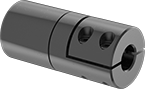
Machinable-Bore Single U-Joints
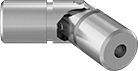 | 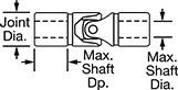 |
Customize the bores of these U-joints to fit the exact dimensions of your shafts. To make drilling easy, they come apart and have a small, centered starter hole on each end. They’re single U-joints, so they connect and transfer torque between two shafts that are misaligned at an angle. A good choice for most applications, all have a pin-and-block joint that handles higher torque at lower speeds than other joint types, such as those with needle bearings. Made of steel, they’re strong and handle a good amount of torque.
To extend their life by keeping lubricant in and contaminants out, use the grooves on their body to add a cover (sometimes called bellows or boots). Drill holes through the U-joint and your shafts and then connect using spring pins.
Your shafts' misalignment will affect the speed and torque the U-joint will be able to transmit. The more the shafts are misaligned, the less speed and torque the U-joint will be able to transmit.
Torque | ||||||||||||||
|---|---|---|---|---|---|---|---|---|---|---|---|---|---|---|
For Max. Shaft Dia. | For Max. Shaft Dp. | Joint Dia. | Overall Lg. | Max. Operating Angle | Max. Rotation Speed, rpm | Max. Torque, in·lbf | 3° Operating Angle | 10° Operating Angle | Joint Type | For Shaft Type | Each | |||
Steel | ||||||||||||||
| 3/8" | 5/8" | 1/2" | 2" | 25° | 1,750 | 375 | 150 in·lbf @ 300 rpm | 51 in·lbf @ 300 rpm | Pin and Block | Round | 6443K12 | 000000 | ||
| 1/2" | 11/16" | 5/8" | 2 1/4" | 25° | 1,750 | 540 | 245 in·lbf @ 300 rpm | 83 in·lbf @ 300 rpm | Pin and Block | Round | 6443K42 | 00000 | ||
| 5/8" | 7/8" | 3/4" | 2 11/16" | 25° | 1,750 | 765 | 330 in·lbf @ 300 rpm | 110 in·lbf @ 300 rpm | Pin and Block | Round | 6443K13 | 00000 | ||
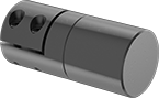
Machinable-Bore Double U-Joints
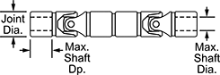 | |
Drill custom bore sizes to connect shafts that are either parallel to each other or are misaligned at an angle. These double U-joints come apart and have a small, centered hole on each end to make drilling easy. Besides transferring torque, they keep parallel shafts moving in sync by making the output shaft move at the same rate as the input shaft. They have a pin-and-block joint, so they handle higher torque at lower speeds than other joint types such as those with needle bearings, making them a good choice for most applications. Made of steel, they’re strong and handle a good amount of torque.
To extend their life by keeping lubricant in and contaminants out, use the grooves on their body to add a cover (sometimes called bellows or boots). Drill holes through the U-joint and your shafts and then connect using spring pins.
Your shafts' misalignment will affect the speed and torque the U-joint will be able to transmit. The more the shafts are misaligned, the less speed and torque the U-joint will be able to transmit.
Torque | |||||||||||||||
|---|---|---|---|---|---|---|---|---|---|---|---|---|---|---|---|
For Max. Shaft Dia. | For Max. Shaft Dp. | Joint Dia. | Overall Lg. | Max. Operating Angle | Max. Rotation Speed, rpm | Max. Torque, in·lbf | 3° Operating Angle | 10° Operating Angle | Parallel Misalignment Capability | Joint Type | For Shaft Type | Each | |||
Steel | |||||||||||||||
| 3/8" | 5/8" | 1/2" | 4" | 25° | 1,750 | 375 | 150 in·lbf @ 300 rpm | 51 in·lbf @ 300 rpm | 0.845" | Pin and Block | Round | 6443K15 | 0000000 | ||
| 1/2" | 11/16" | 5/8" | 4 1/2" | 25° | 1,750 | 540 | 245 in·lbf @ 300 rpm | 83 in·lbf @ 300 rpm | 0.951" | Pin and Block | Round | 6443K52 | 000000 | ||
| 5/8" | 7/8" | 3/4" | 5 3/8" | 25° | 1,750 | 765 | 330 in·lbf @ 300 rpm | 110 in·lbf @ 300 rpm | 1.133" | Pin and Block | Round | 6443K63 | 000000 | ||
| 3/4" | 1" | 1" | 6 3/4" | 25° | 1,750 | 1,560 | 595 in·lbf @ 300 rpm | 200 in·lbf @ 300 rpm | 1.428" | Pin and Block | Round | 6443K55 | 000000 | ||
| 1" | 1 1/16" | 1 1/4" | 7 1/2" | 25° | 1,750 | 5,220 | 980 in·lbf @ 300 rpm | 330 in·lbf @ 300 rpm | 1.585" | Pin and Block | Round | 6443K29 | 000000 | ||
| 1 1/8" | 1 3/16" | 1 1/2" | 8 1/2" | 25° | 1,750 | 7,920 | 1,425 in·lbf @ 300 rpm | 480 in·lbf @ 300 rpm | 1.796" | Pin and Block | Round | 6443K38 | 000000 | ||
