


Filter by
Maximum Pull
Wire Connection
Electrical Connection
RoHS
DFARS Specialty Metals
Export Control Classification Number (ECCN)
Material


About Magnets
Choose a magnet with the right strength, material, and temperature resistance for your application.
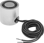
Hardwire Electromagnets
Disc
 |
Spring-Loaded Release—Magnets with spring-loaded release have a pin that pops up to separate the object and magnet when the power is turned off.
Wattage, W | OD | Ht. | Max. Pull, lbf | Sets of Poles | Max. Temp., ° F | Thread Size | Thread Dp. | No. of Mounting Holes | Mounting Hole Ctr.-to-Ctr. | Wire Lead Lg. | Features | Each | |||||||||||||||||||||||||||||||||||||||||||||||||||||||||||||||||||||||||||||||||||||||
|---|---|---|---|---|---|---|---|---|---|---|---|---|---|---|---|---|---|---|---|---|---|---|---|---|---|---|---|---|---|---|---|---|---|---|---|---|---|---|---|---|---|---|---|---|---|---|---|---|---|---|---|---|---|---|---|---|---|---|---|---|---|---|---|---|---|---|---|---|---|---|---|---|---|---|---|---|---|---|---|---|---|---|---|---|---|---|---|---|---|---|---|---|---|---|---|---|---|---|---|
12V DC | |||||||||||||||||||||||||||||||||||||||||||||||||||||||||||||||||||||||||||||||||||||||||||||||||||
| 1.4 | 1/2" | 1 1/2" | 4 | 1 | 100 | 6-32 | 1/2" | 1 | — | 24" | — | 5698K7 | 0000000 | ||||||||||||||||||||||||||||||||||||||||||||||||||||||||||||||||||||||||||||||||||||||
| 1.4 | 3/4" | 1 1/4" | 9 | 1 | 100 | 10-32 | 3/8" | 1 | — | 24" | — | 5698K111 | 00000 | ||||||||||||||||||||||||||||||||||||||||||||||||||||||||||||||||||||||||||||||||||||||
| 1.4 | 1" | 3/4" | 26 | 1 | 100 | 10-32 | 3/8" | 1 | — | 24" | — | 5698K112 | 00000 | ||||||||||||||||||||||||||||||||||||||||||||||||||||||||||||||||||||||||||||||||||||||
| 3.6 | 1" | 1 1/4" | 32 | 1 | 100 | 10-32 | 1/2" | 1 | — | 24" | — | 5698K113 | 00000 | ||||||||||||||||||||||||||||||||||||||||||||||||||||||||||||||||||||||||||||||||||||||
| 4.4 | 1 1/4" | 1 1/4" | 50 | 1 | 100 | 1/4"-20 | 1/2" | 1 | — | 24" | — | 5698K114 | 00000 | ||||||||||||||||||||||||||||||||||||||||||||||||||||||||||||||||||||||||||||||||||||||
| 4.6 | 1 1/2" | 1 1/2" | 80 | 1 | 100 | 1/4"-20 | 1/2" | 1 | — | 24" | — | 5698K115 | 00000 | ||||||||||||||||||||||||||||||||||||||||||||||||||||||||||||||||||||||||||||||||||||||
| 5.6 | 2" | 1 5/8" | 180 | 1 | 100 | 1/4"-20 | 1/2" | 1 | — | 24" | — | 5698K116 | 00000 | ||||||||||||||||||||||||||||||||||||||||||||||||||||||||||||||||||||||||||||||||||||||
24V DC | |||||||||||||||||||||||||||||||||||||||||||||||||||||||||||||||||||||||||||||||||||||||||||||||||||
| 0.9 | 25/32" | 63/64" | 1 | 1 | 100 | M5 x 0.8 mm | 0.19" | 1 | — | 8" | Spring-Loaded Release | 5893K92 | 000000 | ||||||||||||||||||||||||||||||||||||||||||||||||||||||||||||||||||||||||||||||||||||||
| 1.4 | 1/2" | 1 1/2" | 4 | 1 | 100 | 6-32 | 3/8" | 1 | — | 24" | — | 5698K97 | 000000 | ||||||||||||||||||||||||||||||||||||||||||||||||||||||||||||||||||||||||||||||||||||||
| 1.4 | 3/4" | 1 1/4" | 9 | 1 | 100 | 10-32 | 3/8" | 1 | — | 24" | — | 5698K211 | 00000 | ||||||||||||||||||||||||||||||||||||||||||||||||||||||||||||||||||||||||||||||||||||||
| 1.4 | 1" | 3/4" | 26 | 1 | 100 | 10-32 | 3/8" | 1 | — | 24" | — | 5698K212 | 00000 | ||||||||||||||||||||||||||||||||||||||||||||||||||||||||||||||||||||||||||||||||||||||
| 2 | 1.18" | 63/64" | 6 | 1 | 100 | M6 x 1 mm | 0.23" | 1 | — | 8" | Spring-Loaded Release | 5893K94 | 000000 | ||||||||||||||||||||||||||||||||||||||||||||||||||||||||||||||||||||||||||||||||||||||
| 2.9 | 1.57" | 63/64" | 22 | 1 | 100 | M6 x 1 mm | 0.29" | 1 | — | 8" | Spring-Loaded Release | 5893K96 | 000000 | ||||||||||||||||||||||||||||||||||||||||||||||||||||||||||||||||||||||||||||||||||||||
| 3.6 | 1" | 1 1/4" | 32 | 1 | 100 | 10-32 | 1/2" | 1 | — | 24" | — | 5698K213 | 00000 | ||||||||||||||||||||||||||||||||||||||||||||||||||||||||||||||||||||||||||||||||||||||
| 4.4 | 1 1/4" | 1 1/4" | 50 | 1 | 100 | 1/4"-20 | 1/2" | 1 | — | 24" | — | 5698K214 | 00000 | ||||||||||||||||||||||||||||||||||||||||||||||||||||||||||||||||||||||||||||||||||||||
| 4.6 | 1 1/2" | 1 1/2" | 80 | 1 | 100 | 1/4"-20 | 1/2" | 1 | — | 24" | — | 5698K215 | 00000 | ||||||||||||||||||||||||||||||||||||||||||||||||||||||||||||||||||||||||||||||||||||||
| 5.6 | 2" | 1 5/8" | 180 | 1 | 100 | 1/4"-20 | 1/2" | 1 | — | 24" | — | 5698K216 | 00000 | ||||||||||||||||||||||||||||||||||||||||||||||||||||||||||||||||||||||||||||||||||||||
110V DC | |||||||||||||||||||||||||||||||||||||||||||||||||||||||||||||||||||||||||||||||||||||||||||||||||||
| 8 | 3 1/2" | 1 1/2" | 650 | 1 | 100 | 1/4"-20 | 1/2" | 2 | 1" | 24" | — | 5698K76 | 000000 | ||||||||||||||||||||||||||||||||||||||||||||||||||||||||||||||||||||||||||||||||||||||
| 33 | 4" | 3" | 1,000 | 1 | 100 | 3/8"-16 | 5/8" | 2 | 1" | 24" | — | 5698K77 | 000000 | ||||||||||||||||||||||||||||||||||||||||||||||||||||||||||||||||||||||||||||||||||||||
| 60 | 10" | 2 1/2" | 4,700 | 1 | 100 | 5/8"-11 | 2" | 2 | 3" | 72" | — | 5698K75 | 00000000 | ||||||||||||||||||||||||||||||||||||||||||||||||||||||||||||||||||||||||||||||||||||||
Plug-In Electromagnets
Disc
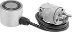 |
Wattage, W | OD | Ht. | Max. Pull, lbf | Sets of Poles | Max. Temp., ° F | Thread Size | Thread Dp. | No. of Mounting Holes | Cord Lg., ft. | Each | |||||||||||||||||||||||||||||||||||||||||||||||||||||||||||||||||||||||||||||||||||||||||
|---|---|---|---|---|---|---|---|---|---|---|---|---|---|---|---|---|---|---|---|---|---|---|---|---|---|---|---|---|---|---|---|---|---|---|---|---|---|---|---|---|---|---|---|---|---|---|---|---|---|---|---|---|---|---|---|---|---|---|---|---|---|---|---|---|---|---|---|---|---|---|---|---|---|---|---|---|---|---|---|---|---|---|---|---|---|---|---|---|---|---|---|---|---|---|---|---|---|---|---|
120V AC | |||||||||||||||||||||||||||||||||||||||||||||||||||||||||||||||||||||||||||||||||||||||||||||||||||
| 2.8 | 1 1/4" | 1 1/4" | 40 | 1 | 100 | 1/4"-20 | 3/8" | 1 | 3 | 5692K32 | 0000000 | ||||||||||||||||||||||||||||||||||||||||||||||||||||||||||||||||||||||||||||||||||||||||
| 3.6 | 1 3/4" | 1 5/8" | 110 | 1 | 100 | 1/4"-20 | 1/2" | 1 | 3 | 5692K33 | 000000 | ||||||||||||||||||||||||||||||||||||||||||||||||||||||||||||||||||||||||||||||||||||||||
| 8 | 2" | 1 5/8" | 90 | 1 | 100 | 1/4"-20 | 1/2" | 1 | 3 | 5692K34 | 000000 | ||||||||||||||||||||||||||||||||||||||||||||||||||||||||||||||||||||||||||||||||||||||||
| 14 | 2" | 2 1/2" | 100 | 1 | 100 | 1/4"-20 | 1/2" | 1 | 3 | 5692K35 | 000000 | ||||||||||||||||||||||||||||||||||||||||||||||||||||||||||||||||||||||||||||||||||||||||
| 25 | 3" | 3" | 200 | 1 | 100 | 5/16"-18 | 1/2" | 1 | 3 | 5692K38 | 000000 | ||||||||||||||||||||||||||||||||||||||||||||||||||||||||||||||||||||||||||||||||||||||||
Ferrite Cores
