Filter by
Pipe Size
Fitting Type


Pipe Material
Fitting Connection


Maximum Pressure @ Temperature
ID
DFARS Specialty Metals
Specifications Met
Nut Material

About Pipe and Fittings
Measure your pipe and fittings to identify their pipe size, thread size, schedule, and thread type. Then, find compatible components.
Thick-Wall Plastic Pipe Fittings for Water
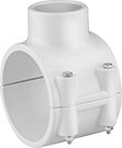
Saddle Tap Tees with Collar and Gasket
 |
Female x Clamp On |
Saddle-tap tee adapters allow you to create additional outlets and connections in metal or plastic pipe. To install, shut down your line and drill a hole in the pipe where you want to create a connection. Position the saddle over the hole so the gasket and lip are fully engaged and secure with the included nuts, bolts, and washers.
Fittings with collar have a stainless steel reinforcement on the female threads to prevent the threads from cracking.
NSF/ANSI 61—To adhere to safety standards for drinking water systems, use pipe that meets NSF/ANSI 61.
Pipe Size (A) | For Pipe Size (B) | For Pipe OD (B) | For Hole Dia. | Pipe Schedule | Material | Color | Max. Pressure @ Temp. | Gasket Material | Food Industry Std. | Each | |||
|---|---|---|---|---|---|---|---|---|---|---|---|---|---|
NPT Female × Clamp On | |||||||||||||
| 1/2 | 2 | 2 3/8" | 3/4" | 80 | PVC | Dark Gray | 200 psi @ 72° F | EPDM | NSF/ANSI 61 | 4849K51 | 000000 | ||
| 1/2 | 3 | 3 1/2" | 7/8" | 80 | PVC | Dark Gray | 200 psi @ 72° F | EPDM | NSF/ANSI 61 | 4849K56 | 00000 | ||
| 1/2 | 4 | 4 1/2" | 1 1/8" | 80 | PVC | Dark Gray | 200 psi @ 72° F | EPDM | NSF/ANSI 61 | 4849K63 | 000000 | ||
| 3/4 | 2 | 2 3/8" | 7/8" | 80 | PVC | Dark Gray | 200 psi @ 72° F | EPDM | NSF/ANSI 61 | 4849K52 | 00000 | ||
| 3/4 | 3 | 3 1/2" | 7/8" | 80 | PVC | Dark Gray | 200 psi @ 72° F | EPDM | NSF/ANSI 61 | 4849K57 | 00000 | ||
| 3/4 | 4 | 4 1/2" | 1 1/8" | 80 | PVC | Dark Gray | 200 psi @ 72° F | EPDM | NSF/ANSI 61 | 4849K64 | 000000 | ||
| 1 | 2 | 2 3/8" | 1 1/8" | 80 | PVC | Dark Gray | 200 psi @ 72° F | EPDM | NSF/ANSI 61 | 4849K53 | 00000 | ||
| 1 | 3 | 3 1/2" | 1 1/8" | 80 | PVC | Dark Gray | 200 psi @ 72° F | EPDM | NSF/ANSI 61 | 4849K58 | 00000 | ||
| 1 | 4 | 4 1/2" | 1 1/8" | 80 | PVC | Dark Gray | 200 psi @ 72° F | EPDM | NSF/ANSI 61 | 4849K65 | 000000 | ||
| 1 1/2 | 3 | 3 1/2" | 2 1/4" | 80 | PVC | Dark Gray | 200 psi @ 72° F | EPDM | NSF/ANSI 61 | 4849K61 | 00000 | ||
| 1 1/2 | 4 | 4 1/2" | 1 3/4" | 80 | PVC | Dark Gray | 200 psi @ 72° F | EPDM | NSF/ANSI 61 | 4849K67 | 000000 | ||
| 2 | 4 | 4 1/2" | 2 1/4" | 80 | PVC | Dark Gray | 200 psi @ 72° F | EPDM | NSF/ANSI 61 | 4849K68 | 000000 | ||
| 2 | 6 | 6 5/8" | 2 1/4" | 80 | PVC | Dark Gray | 200 psi @ 72° F | EPDM | NSF/ANSI 61 | 4849K82 | 000000 | ||
Low-Pressure Iron and Steel Threaded Pipe Fittings
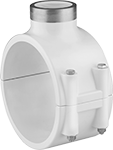
Saddle Tap Tees with Gasket
 |
Female × Clamp On |
Saddle tap tees tap into existing pipe lines so you can install branch lines, valves, and other equipment. The gasket and clamps create a tight seal so the opening won’t leak. To install, shut down your line and secure the clamps, then drill a hole into the pipe.
For Pipe OD | ||||||||||||
|---|---|---|---|---|---|---|---|---|---|---|---|---|
Pipe Size (A) | For Pipe Size (B) | (B) | (B) | Material | Color | Max. Pressure @ Temp. | Gasket Material | Clamp Material | Each | |||
NPT Female × Clamp On | ||||||||||||
| 1/2 | 1 1/2, 1 1/4 | 1.9" | 1.66" | Epoxy-Coated Iron | Blue | 100 psi @ 72° F | Buna-N | Galvanized Steel | 4572K211 | 000000 | ||
| 1/2 | 2 | 2 3/8" | — | Epoxy-Coated Iron | Blue | 100 psi @ 72° F | Buna-N | Galvanized Steel | 4572K212 | 00000 | ||
| 1/2 | 3 | 3 1/2" | — | Epoxy-Coated Iron | Blue | 100 psi @ 72° F | Buna-N | Galvanized Steel | 4572K213 | 00000 | ||
| 1/2 | 4 | 4 1/2" | — | Epoxy-Coated Iron | Blue | 100 psi @ 72° F | Buna-N | Galvanized Steel | 4572K214 | 00000 | ||
| 1/2 | 6 | 6 5/8" | — | Epoxy-Coated Iron | Blue | 100 psi @ 72° F | Buna-N | Galvanized Steel | 4572K215 | 00000 | ||
| 1/2 | 8 | 8 5/8" | — | Epoxy-Coated Iron | Blue | 100 psi @ 72° F | Buna-N | Galvanized Steel | 4572K216 | 00000 | ||
| 3/4 | 1 1/2, 1 1/4 | 1.9" | 1.66" | Epoxy-Coated Iron | Blue | 100 psi @ 72° F | Buna-N | Galvanized Steel | 4572K221 | 00000 | ||
| 3/4 | 2 | 2 3/8" | — | Epoxy-Coated Iron | Blue | 100 psi @ 72° F | Buna-N | Galvanized Steel | 4572K222 | 00000 | ||
| 3/4 | 3 | 3 1/2" | — | Epoxy-Coated Iron | Blue | 100 psi @ 72° F | Buna-N | Galvanized Steel | 4572K223 | 00000 | ||
| 3/4 | 4 | 4 1/2" | — | Epoxy-Coated Iron | Blue | 100 psi @ 72° F | Buna-N | Galvanized Steel | 4572K224 | 00000 | ||
| 3/4 | 6 | 6 5/8" | — | Epoxy-Coated Iron | Blue | 100 psi @ 72° F | Buna-N | Galvanized Steel | 4572K225 | 00000 | ||
| 3/4 | 8 | 8 5/8" | — | Epoxy-Coated Iron | Blue | 100 psi @ 72° F | Buna-N | Galvanized Steel | 4572K226 | 00000 | ||
| 1 | 1 1/2, 1 1/4 | 1.9" | 1.66" | Epoxy-Coated Iron | Blue | 100 psi @ 72° F | Buna-N | Galvanized Steel | 4572K231 | 00000 | ||
| 1 | 2 | 2 3/8" | — | Epoxy-Coated Iron | Blue | 100 psi @ 72° F | Buna-N | Galvanized Steel | 4572K232 | 00000 | ||
| 1 | 3 | 3 1/2" | — | Epoxy-Coated Iron | Blue | 100 psi @ 72° F | Buna-N | Galvanized Steel | 4572K233 | 00000 | ||
| 1 | 4 | 4 1/2" | — | Epoxy-Coated Iron | Blue | 100 psi @ 72° F | Buna-N | Galvanized Steel | 4572K234 | 00000 | ||
| 1 | 6 | 6 5/8" | — | Epoxy-Coated Iron | Blue | 100 psi @ 72° F | Buna-N | Galvanized Steel | 4572K235 | 00000 | ||
| 1 | 8 | 8 5/8" | — | Epoxy-Coated Iron | Blue | 100 psi @ 72° F | Buna-N | Galvanized Steel | 4572K236 | 00000 | ||
| 1 1/4 | 2 | 2 3/8" | — | Epoxy-Coated Iron | Blue | 100 psi @ 72° F | Buna-N | Galvanized Steel | 4572K241 | 00000 | ||
| 1 1/4 | 3 | 3 1/2" | — | Epoxy-Coated Iron | Blue | 100 psi @ 72° F | Buna-N | Galvanized Steel | 4572K242 | 00000 | ||
| 1 1/4 | 4 | 4 1/2" | — | Epoxy-Coated Iron | Blue | 100 psi @ 72° F | Buna-N | Galvanized Steel | 4572K243 | 00000 | ||
| 1 1/4 | 6 | 6 5/8" | — | Epoxy-Coated Iron | Blue | 100 psi @ 72° F | Buna-N | Galvanized Steel | 4572K244 | 000000 | ||
| 1 1/4 | 8 | 8 5/8" | — | Epoxy-Coated Iron | Blue | 100 psi @ 72° F | Buna-N | Galvanized Steel | 4572K245 | 000000 | ||
| 1 1/2 | 2 | 2 3/8" | — | Epoxy-Coated Iron | Blue | 100 psi @ 72° F | Buna-N | Galvanized Steel | 4572K251 | 00000 | ||
| 1 1/2 | 3 | 3 1/2" | — | Epoxy-Coated Iron | Blue | 100 psi @ 72° F | Buna-N | Galvanized Steel | 4572K252 | 00000 | ||
| 1 1/2 | 4 | 4 1/2" | — | Epoxy-Coated Iron | Blue | 100 psi @ 72° F | Buna-N | Galvanized Steel | 4572K253 | 00000 | ||
| 1 1/2 | 6 | 6 5/8" | — | Epoxy-Coated Iron | Blue | 100 psi @ 72° F | Buna-N | Galvanized Steel | 4572K254 | 000000 | ||
| 1 1/2 | 8 | 8 5/8" | — | Epoxy-Coated Iron | Blue | 100 psi @ 72° F | Buna-N | Galvanized Steel | 4572K255 | 000000 | ||
| 2 | 3 | 3 1/2" | — | Epoxy-Coated Iron | Blue | 100 psi @ 72° F | Buna-N | Galvanized Steel | 4572K261 | 00000 | ||
| 2 | 4 | 4 1/2" | — | Epoxy-Coated Iron | Blue | 100 psi @ 72° F | Buna-N | Galvanized Steel | 4572K262 | 00000 | ||
| 2 | 6 | 6 5/8" | — | Epoxy-Coated Iron | Blue | 100 psi @ 72° F | Buna-N | Galvanized Steel | 4572K263 | 000000 | ||
| 2 | 8 | 8 5/8" | — | Epoxy-Coated Iron | Blue | 100 psi @ 72° F | Buna-N | Galvanized Steel | 4572K264 | 000000 | ||
180° Bend Connectors
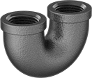 |
180° bend connectors are also known as U-bends.
Pipe Size | Material | Max. Pressure @ Temp. | Max. Steam Pressure @ Temp. | Certification | Shape | Each | |||
|---|---|---|---|---|---|---|---|---|---|
NPT Female | |||||||||
| 1/2 | Iron | 150 psi @ 72° F | 150 psi @ 350° F | UL Listed | 180° Bend | 44605K563 | 000000 | ||
| 3/4 | Iron | 150 psi @ 72° F | 150 psi @ 350° F | UL Listed | 180° Bend | 44605K564 | 00000 | ||
| 1 | Iron | 150 psi @ 72° F | 150 psi @ 350° F | — | 180° Bend | 44605K565 | 00000 | ||
| 1 1/4 | Iron | 150 psi @ 72° F | 150 psi @ 350° F | UL Listed | 180° Bend | 44605K566 | 00000 | ||
| 1 1/2 | Iron | 150 psi @ 72° F | 150 psi @ 350° F | UL Listed | 180° Bend | 44605K567 | 000000 | ||
| 2 | Iron | 150 psi @ 72° F | 150 psi @ 350° F | UL Listed | 180° Bend | 44605K568 | 000000 | ||
Standard-Wall Plastic Pipe Fittings for Water
Saddle Tap Tees with Gasket
 |
Female × Clamp On |
Saddle-tap tee adapters allow you to create additional outlets and connections in metal or plastic pipe. To install, shut down your line and drill a hole in the pipe where you want to create a connection. Position the saddle over the hole so the gasket and lip are fully engaged and secure with the included nuts, bolts, and washers.
Cement-Socket Fitting Connection—Attach socket-connect ends to unthreaded pipe or another socket-connect fitting with a PVC primer and cement (also known as solvent weld).
NSF/ANSI 61—To adhere to safety standards for drinking water systems, use pipe that meets NSF/ANSI 61.
Pipe Size (A) | For Pipe Size (B) | For Pipe OD (B) | For Hole Dia. | OD | Pipe Schedule | Material | Color | Max. Pressure @ Temp. | Gasket Material | Food Industry Std. | Each | |||
|---|---|---|---|---|---|---|---|---|---|---|---|---|---|---|
Cement Socket Female × Clamp On | ||||||||||||||
| 1 1/2 | 3 | 3 1/2" | 2 1/4" | 1 29/32" | 40 | PVC | White | 200 psi @ 72° F | EPDM | NSF/ANSI 61 | 4763K21 | 000000 | ||
| 1 1/2 | 4 | 4 1/2" | 1 3/4" | 1 29/32" | 40 | PVC | White | 200 psi @ 72° F | EPDM | NSF/ANSI 61 | 4763K27 | 000000 | ||
| 2 | 3 | 3 1/2" | 2 1/4" | 2 3/8" | 40 | PVC | White | 200 psi @ 72° F | EPDM | NSF/ANSI 61 | 4763K22 | 00000 | ||
| 2 | 4 | 4 1/2" | 2 1/4" | 2 3/8" | 40 | PVC | White | 200 psi @ 72° F | EPDM | NSF/ANSI 61 | 4763K28 | 000000 | ||
| 2 | 6 | 6 5/8" | 2 1/4" | 2 3/8" | 40 | PVC | White | 200 psi @ 72° F | EPDM | NSF/ANSI 61 | 4763K82 | 000000 | ||
| 3 | 4 | 4 1/2" | 3" | 3 1/2" | 40 | PVC | White | 200 psi @ 72° F | EPDM | NSF/ANSI 61 | 4763K31 | 000000 | ||
Saddle Tap Tees with Collar and Gasket
 |
Female × Clamp On |
Saddle-tap tee adapters allow you to create additional outlets and connections in metal or plastic pipe. To install, shut down your line and drill a hole in the pipe where you want to create a connection. Position the saddle over the hole so the gasket and lip are fully engaged and secure with the included nuts, bolts, and washers.
Fittings with collar have a stainless steel reinforcement on the female threads to prevent the threads from cracking.
NSF/ANSI 61—To adhere to safety standards for drinking water systems, use pipe that meets NSF/ANSI 61.
Pipe Size (A) | For Pipe Size (B) | For Pipe OD (B) | For Hole Dia. | OD | Pipe Schedule | Material | Color | Max. Pressure @ Temp. | Gasket Material | Food Industry Std. | Each | |||
|---|---|---|---|---|---|---|---|---|---|---|---|---|---|---|
NPT Female × Clamp On | ||||||||||||||
| 1/2 | 2 | 2 3/8" | 3/4" | 27/32" | 40 | PVC | White | 200 psi @ 72° F | EPDM | NSF/ANSI 61 | 4763K51 | 000000 | ||
| 3/4 | 2 | 2 3/8" | 7/8" | 1 3/64" | 40 | PVC | White | 200 psi @ 72° F | EPDM | NSF/ANSI 61 | 4763K52 | 00000 | ||
| 3/4 | 4 | 4 1/2" | 1 1/8" | 1 3/64" | 40 | PVC | White | 200 psi @ 72° F | EPDM | NSF/ANSI 61 | 4763K64 | 000000 | ||
| 1 | 2 | 2 3/8" | 1 1/8" | 1 5/16" | 40 | PVC | White | 200 psi @ 72° F | EPDM | NSF/ANSI 61 | 4763K53 | 00000 | ||
| 1 | 4 | 4 1/2" | 1 1/8" | 1 5/16" | 40 | PVC | White | 200 psi @ 72° F | EPDM | NSF/ANSI 61 | 4763K65 | 000000 | ||
| 2 | 6 | 6 5/8" | 2 1/4" | 2 3/8" | 40 | PVC | White | 200 psi @ 72° F | EPDM | NSF/ANSI 61 | 4763K85 | 000000 | ||
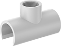
Tee Outlets
 |
Female × Cement Socket |
Tee outlets allow you to create additional outlets and connections in plastic pipe. Use a PVC primer and cement to secure the tee outlet into position, then drill a hole through the fitting and pipe. They are also known as branch connectors.
Cement-Socket Fitting Connection—Attach socket-connect ends to unthreaded pipe or another socket-connect fitting with a PVC primer and cement (also known as solvent weld).
NSF/ANSI 61—To adhere to safety standards for drinking water systems, use pipe that meets NSF/ANSI 61.
Pipe Size (A) | For Pipe Size (B) | Pipe Schedule | Material | Color | Max. Pressure @ Temp. | Food Industry Std. | Each | |||
|---|---|---|---|---|---|---|---|---|---|---|
NPT Female × Cement Socket | ||||||||||
| 1/8 | 1/2 | 40 | PVC | White | Not Rated | NSF/ANSI 61 | 4880K118 | 00000 | ||
| 1/8 | 3/4 | 40 | PVC | White | Not Rated | NSF/ANSI 61 | 4880K119 | 0000 | ||
| 1/2 | 1/2 | 40 | PVC | White | Not Rated | NSF/ANSI 61 | 4880K116 | 0000 | ||
| 1/2 | 3/4 | 40 | PVC | White | Not Rated | NSF/ANSI 61 | 4880K105 | 0000 | ||
| 1/2 | 1 | 40 | PVC | White | Not Rated | NSF/ANSI 61 | 4880K106 | 0000 | ||
| 3/4 | 3/4 | 40 | PVC | White | Not Rated | NSF/ANSI 61 | 4880K104 | 0000 | ||
| 3/4 | 1 | 40 | PVC | White | Not Rated | NSF/ANSI 61 | 4880K107 | 0000 | ||
| 1 | 1 | 40 | PVC | White | Not Rated | NSF/ANSI 61 | 4880K117 | 0000 | ||
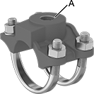
Drain, Waste, and Vent PVC Clamp-On Pipe Fittings for Water
Saddle Tap Tees
 |
Clamp On × Clamp On |
Saddle-tap adapters allow you to tap into an existing pipeline. They have wraparound clamps that provide nearly 360° contact with pipe; as the clamps are tightened, pressure is uniformly distributed around the pipe for maximum support. To install, shut down your line and drill a hole in the pipe where you want to create a connection. Position the saddle over the hole and tighten the clamps.
Saddle Tap Wyes
 |
Clamp On × Clamp On |
Saddle-tap adapters allow you to tap into an existing pipeline. They have wraparound clamps that provide nearly 360° contact with pipe; as the clamps are tightened, pressure is uniformly distributed around the pipe for maximum support. To install, shut down your line and drill a hole in the pipe where you want to create a connection. Position the saddle over the hole and tighten the clamps.
High-Pressure Iron and Steel Threaded Pipe Fittings
Tee Outlets
 |
NPT Female × Butt Weld |
Tee outlets allow you to create a threaded outlet anywhere along a pipe. They are also known as branch connectors and are comparable to Thredolet. To install, drill a hole in your pipe to match the fitting’s pipe size and weld in place.
Zinc-Phosphate-Coated Steel—A phosphate coating offers some corrosion resistance, but these fittings aren't intended for corrosive environments.
Pipe Size (A) | Dash Size (A) | For Pipe Size (B) | Material | Max. Pressure @ Temp. | Max. Steam Pressure @ Temp. | Each | |||
|---|---|---|---|---|---|---|---|---|---|
NPT Female × Butt Weld | |||||||||
| 1/4 | 04 | 1/4 to 3/8 | Zinc-Phosphate-Coated Steel | 3,000 psi @ 72° F | 300 psi @ 360° F | 4587K511 | 000000 | ||
| 1/4 | 04 | 1/2 to 36 | Zinc-Phosphate-Coated Steel | 3,000 psi @ 72° F | 300 psi @ 360° F | 4587K21 | 00000 | ||
| 3/8 | 06 | 3/8 to 1 | Zinc-Phosphate-Coated Steel | 3,000 psi @ 72° F | 300 psi @ 360° F | 4587K521 | 00000 | ||
| 3/8 | 06 | 1 1/4 to 36 | Zinc-Phosphate-Coated Steel | 3,000 psi @ 72° F | 300 psi @ 360° F | 4587K22 | 00000 | ||
| 1/2 | 08 | 1/2 | Zinc-Phosphate-Coated Steel | 3,000 psi @ 72° F | 300 psi @ 360° F | 4587K531 | 00000 | ||
| 1/2 | 08 | 3/4 to 36 | Zinc-Phosphate-Coated Steel | 3,000 psi @ 72° F | 300 psi @ 360° F | 4587K23 | 00000 | ||
| 3/4 | 12 | 3/4 to 1 1/4 | Zinc-Phosphate-Coated Steel | 3,000 psi @ 72° F | 300 psi @ 360° F | 4587K541 | 00000 | ||
| 3/4 | 12 | 1 1/2 to 36 | Zinc-Phosphate-Coated Steel | 3,000 psi @ 72° F | 300 psi @ 360° F | 4587K24 | 00000 | ||
| 1 | 16 | 1 | Zinc-Phosphate-Coated Steel | 3,000 psi @ 72° F | 300 psi @ 360° F | 4587K551 | 00000 | ||
| 1 | 16 | 1 1/4 to 2 1/2 | Zinc-Phosphate-Coated Steel | 3,000 psi @ 72° F | 300 psi @ 360° F | 4587K552 | 00000 | ||
| 1 | 16 | 3 to 36 | Zinc-Phosphate-Coated Steel | 3,000 psi @ 72° F | 300 psi @ 360° F | 4587K25 | 00000 | ||
| 1 1/4 | 20 | 1 1/4 to 1 1/2 | Zinc-Phosphate-Coated Steel | 3,000 psi @ 72° F | 300 psi @ 360° F | 4587K561 | 00000 | ||
| 1 1/4 | 20 | 2 to 3 1/2 | Zinc-Phosphate-Coated Steel | 3,000 psi @ 72° F | 300 psi @ 360° F | 4587K562 | 00000 | ||
| 1 1/4 | 20 | 4 to 36 | Zinc-Phosphate-Coated Steel | 3,000 psi @ 72° F | 300 psi @ 360° F | 4587K26 | 00000 | ||
| 1 1/2 | 24 | 1 1/2 | Zinc-Phosphate-Coated Steel | 3,000 psi @ 72° F | 300 psi @ 360° F | 4587K571 | 00000 | ||
| 1 1/2 | 24 | 2 to 2 1/2 | Zinc-Phosphate-Coated Steel | 3,000 psi @ 72° F | 300 psi @ 360° F | 4587K572 | 00000 | ||
| 1 1/2 | 24 | 3 to 5 | Zinc-Phosphate-Coated Steel | 3,000 psi @ 72° F | 300 psi @ 360° F | 4587K573 | 00000 | ||
| 1 1/2 | 24 | 6 to 36 | Zinc-Phosphate-Coated Steel | 3,000 psi @ 72° F | 300 psi @ 360° F | 4587K27 | 00000 | ||
| 2 | 32 | 2 | Zinc-Phosphate-Coated Steel | 3,000 psi @ 72° F | 300 psi @ 360° F | 4587K581 | 00000 | ||
| 2 | 32 | 2 1/2 to 3 1/2 | Zinc-Phosphate-Coated Steel | 3,000 psi @ 72° F | 300 psi @ 360° F | 4587K582 | 00000 | ||
| 2 | 32 | 4 to 6 | Zinc-Phosphate-Coated Steel | 3,000 psi @ 72° F | 300 psi @ 360° F | 4587K281 | 00000 | ||
| 2 | 32 | 8 to 36 | Zinc-Phosphate-Coated Steel | 3,000 psi @ 72° F | 300 psi @ 360° F | 4587K29 | 00000 | ||
High-Pressure Iron and Steel Socket-Connect Pipe Fittings
Tee Outlets
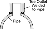 |  |
Socket Connect Female × Butt Weld |
Pipe Size (A) | Dash Size (A) | For Pipe Size (B) | Material | Max. Pressure @ Temp. | Max. Steam Pressure @ Temp. | Each | |||
|---|---|---|---|---|---|---|---|---|---|
Socket Connect Female × Butt Weld | |||||||||
| 1/4 | 04 | 3/8 to 36 | Steel | 3,000 psi @ 72° F | 300 psi @ 360° F | 4587K31 | 000000 | ||
| 3/8 | 06 | 3/4 to 36 | Steel | 3,000 psi @ 72° F | 300 psi @ 360° F | 4587K32 | 00000 | ||
| 1/2 | 08 | 3/4 to 36 | Steel | 3,000 psi @ 72° F | 300 psi @ 360° F | 4587K33 | 00000 | ||
| 3/4 | 12 | 3/4 to 1 1/4 | Steel | 3,000 psi @ 72° F | 300 psi @ 360° F | 4587K94 | 00000 | ||
| 3/4 | 12 | 1 1/2 to 36 | Steel | 3,000 psi @ 72° F | 300 psi @ 360° F | 4587K34 | 00000 | ||
| 1 | 16 | 1 | Steel | 3,000 psi @ 72° F | 300 psi @ 360° F | 4587K95 | 00000 | ||
| 1 | 16 | 1 1/4 to 2 1/2 | Steel | 3,000 psi @ 72° F | 300 psi @ 360° F | 4587K75 | 00000 | ||
| 1 | 16 | 3 to 36 | Steel | 3,000 psi @ 72° F | 300 psi @ 360° F | 4587K35 | 00000 | ||
| 1 1/4 | 20 | 1 1/4 to 1 1/2 | Steel | 3,000 psi @ 72° F | 300 psi @ 360° F | 4587K96 | 00000 | ||
| 1 1/4 | 20 | 2 to 3 1/2 | Steel | 3,000 psi @ 72° F | 300 psi @ 360° F | 4587K76 | 00000 | ||
| 1 1/4 | 20 | 4 to 36 | Steel | 3,000 psi @ 72° F | 300 psi @ 360° F | 4587K36 | 00000 | ||
| 1 1/2 | 24 | 1 1/2 | Steel | 3,000 psi @ 72° F | 300 psi @ 360° F | 4587K97 | 00000 | ||
| 1 1/2 | 24 | 2 to 2 1/2 | Steel | 3,000 psi @ 72° F | 300 psi @ 360° F | 4587K77 | 00000 | ||
| 1 1/2 | 24 | 3 to 5 | Steel | 3,000 psi @ 72° F | 300 psi @ 360° F | 4587K87 | 00000 | ||
| 1 1/2 | 24 | 6 to 36 | Steel | 3,000 psi @ 72° F | 300 psi @ 360° F | 4587K37 | 00000 | ||
| 2 | 32 | 2 | Steel | 3,000 psi @ 72° F | 300 psi @ 360° F | 4587K98 | 00000 | ||
| 2 | 32 | 2 1/2 to 3 1/2 | Steel | 3,000 psi @ 72° F | 300 psi @ 360° F | 4587K78 | 00000 | ||
| 2 | 32 | 4 to 6 | Steel | 3,000 psi @ 72° F | 300 psi @ 360° F | 4587K381 | 00000 | ||
| 2 | 32 | 8 to 36 | Steel | 3,000 psi @ 72° F | 300 psi @ 360° F | 4587K88 | 00000 | ||
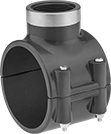
Low-Pressure Aluminum Quick-Connect Pipe Fittings
Saddle Tap Tees
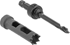 | 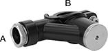 | 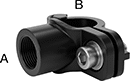 |
Hole Saw | Tee | Tee |
Taps | Hole Saws | |||||||||
|---|---|---|---|---|---|---|---|---|---|---|
For Pipe OD | ||||||||||
Pipe Size (A) | (A) | (B) | Material | Max. Pressure @ Temp. | Each | Each | ||||
NPT Female × Quick Disconnect | ||||||||||
| 1/2 | — | 25 mm, 1" | Epoxy-Coated 6061 Aluminum | 580 psi @ 72° F | 5314N64 | 000000 | 5314N78 | 000000 | ||
| 1/2 | — | 25 mm, 1" | Epoxy-Coated 6061 Aluminum | 580 psi @ 72° F | 5314N71 | 00000 | 5314N78 | 00000 | ||
| 1/2 | — | 40 mm, 1 1/2" | Epoxy-Coated 6061 Aluminum | 580 psi @ 72° F | 5314N65 | 00000 | 5314N78 | 00000 | ||
| 1/2 | — | 40 mm, 1 1/2" | Epoxy-Coated 6061 Aluminum | 580 psi @ 72° F | 5314N72 | 00000 | 5314N79 | 00000 | ||
| 3/4 | — | 40 mm, 1 1/2" | Epoxy-Coated 6061 Aluminum | 580 psi @ 72° F | 5314N66 | 00000 | 5314N79 | 00000 | ||
| 3/4 | — | 40 mm, 1 1/2" | Epoxy-Coated 6061 Aluminum | 580 psi @ 72° F | 5314N73 | 00000 | 5314N79 | 00000 | ||
Quick-Connect Female × Quick Disconnect | ||||||||||
| — | 3/4" (20 mm) | 25 mm, 1" | Epoxy-Coated 6061 Aluminum | 580 psi @ 72° F | 5314N67 | 00000 | 5314N78 | 00000 | ||
| — | 3/4" (20 mm) | 40 mm, 1 1/2" | Epoxy-Coated 6061 Aluminum | 580 psi @ 72° F | 5314N68 | 00000 | 5314N79 | 00000 | ||
| — | 1" (25 mm) | 40 mm, 1 1/2" | Epoxy-Coated 6061 Aluminum | 580 psi @ 72° F | 5314N69 | 00000 | 5314N79 | 00000 | ||
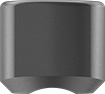
Measuring Tools
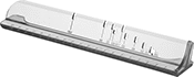 |
Max. Dp. Measured, mm | Lg., mm | Wd., mm | Material | Each | ||
|---|---|---|---|---|---|---|
| 160 | 224 | 39 | Plastic | 5314N77 | 000000 |
Medium-Pressure Iron and Steel Butt-Weld Pipe Fittings
Tee Outlets
 |
Butt Weld × Butt Weld |
Tee outlets allow you to create a tap anywhere along a pipe. They are known as branch connectors and are comparable to Weldolet. To install, drill a hole in your pipe to match the fitting's pipe size and weld in place.
Pipe Size (A) | For Pipe Size (B) | Construction | Material | Max. Pressure @ Temp. | Max. Steam Pressure @ Temp. | Each | |||
|---|---|---|---|---|---|---|---|---|---|
Butt Weld × Butt Weld | |||||||||
| 1/4 | 1/2 to 36 | Seamless | Steel | 3,000 psi @ 72° F | 3,000 psi @ 210° F | 1875N12 | 000000 | ||
| 1/2 | 1/2 | Seamless | Steel | 3,000 psi @ 72° F | 3,000 psi @ 210° F | 1875N15 | 00000 | ||
| 1/2 | 3/4 to 36 | Seamless | Steel | 3,000 psi @ 72° F | 3,000 psi @ 210° F | 1875N16 | 00000 | ||
| 3/4 | 3/4 to 1 1/4 | Seamless | Steel | 3,000 psi @ 72° F | 3,000 psi @ 210° F | 1875N17 | 00000 | ||
| 3/4 | 1 1/2 to 36 | Seamless | Steel | 3,000 psi @ 72° F | 3,000 psi @ 210° F | 1875N18 | 00000 | ||
| 1 | 1 | Seamless | Steel | 3,000 psi @ 72° F | 3,000 psi @ 210° F | 1875N19 | 00000 | ||
| 1 | 1 1/4 to 2 1/2 | Seamless | Steel | 3,000 psi @ 72° F | 3,000 psi @ 210° F | 1875N21 | 00000 | ||
| 1 | 3 to 36 | Seamless | Steel | 3,000 psi @ 72° F | 3,000 psi @ 210° F | 1875N22 | 00000 | ||
| 1 1/4 | 2 to 3 1/2 | Seamless | Steel | 3,000 psi @ 72° F | 3,000 psi @ 210° F | 1875N24 | 00000 | ||
| 1 1/4 | 4 to 36 | Seamless | Steel | 3,000 psi @ 72° F | 3,000 psi @ 210° F | 1875N25 | 00000 | ||
| 1 1/2 | 1 1/2 | Seamless | Steel | 2,800 psi @ 72° F | 2,800 psi @ 210° F | 1875N26 | 00000 | ||
| 1 1/2 | 2 to 2 1/2 | Seamless | Steel | 2,800 psi @ 72° F | 2,800 psi @ 210° F | 1875N27 | 00000 | ||
| 1 1/2 | 3 to 5 | Seamless | Steel | 2,800 psi @ 72° F | 2,800 psi @ 210° F | 1875N28 | 00000 | ||
| 2 | 2 | Seamless | Steel | 2,300 psi @ 72° F | 2,300 psi @ 210° F | 1875N31 | 000000 | ||
| 2 | 2 1/2 to 3 1/2 | Seamless | Steel | 2,300 psi @ 72° F | 2,300 psi @ 210° F | 1875N32 | 00000 | ||
| 2 | 4 to 6 | Seamless | Steel | 2,300 psi @ 72° F | 2,300 psi @ 210° F | 1875N33 | 00000 | ||
| 2 | 8 to 36 | Seamless | Steel | 2,300 psi @ 72° F | 2,300 psi @ 210° F | 1875N34 | 00000 | ||
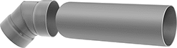
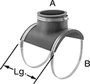
Quick-Disconnect Duct and Fittings
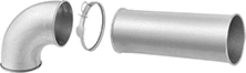 |
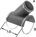
The fastest ductwork to disassemble for dust collection and other frequently cleaned systems. Join sections with quick-release clamps that open and close with a flip of the latch. Since you don’t need screws, welds, or tools, the installation time is half that of other duct types.

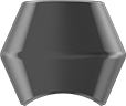
30° Wye Saddles
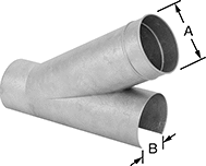 |
Duct Size | Galvanized Steel | Corrosion-Resistant 304 Stainless Steel | |||||||
|---|---|---|---|---|---|---|---|---|---|
(A) | (B) | ID | Ga. | Each | Each | ||||
| 3 | 4 | 3 1/16" | 22 | 1761K401 | 000000 | ——— | 0 | ||
| 4 | 5 | 3 7/8" | 22 | 1761K402 | 00000 | ——— | 0 | ||
| 5 | 6 | 4 7/8" | 22 | 1761K403 | 00000 | ——— | 0 | ||
| 6 | 6 | 5 7/8" | 22 | 1761K56 | 00000 | 2538K221 | 0000000 | ||
| 6 | 7 | 5 7/8" | 22 | 1761K404 | 00000 | ——— | 0 | ||
| 6 | 8 | 5 7/8" | 22 | 1761K57 | 000000 | 2538K222 | 000000 | ||
| 6 | 10 | 5 7/8" | 22 | 1761K58 | 000000 | 2538K223 | 000000 | ||
| 6 | 12 | 5 7/8" | 22 | 1761K225 | 000000 | 2538K224 | 000000 | ||
| 7 | 8 | 6 7/8" | 22 | 1761K405 | 00000 | ——— | 0 | ||
| 8 | 9 | 7 7/8" | 22 | 1761K406 | 00000 | ——— | 0 | ||
| 9 | 10 | 8 7/8" | 22 | 1761K407 | 000000 | ——— | 0 | ||
| 10 | 12 | 9 7/8" | 22 | 1761K408 | 000000 | ——— | 0 | ||
| 12 | 14 | 12" | 20 | 1761K409 | 000000 | ——— | 0 | ||
| 14 | 16 | 13 15/16" | 20 | 1761K411 | 000000 | ——— | 0 | ||
| 16 | 18 | 16" | 20 | 1761K412 | 000000 | ——— | 0 | ||
| 18 | 20 | 17 15/16" | 20 | 1761K413 | 000000 | ——— | 0 | ||
| 20 | 22 | 19 15/16" | 20 | 1761K414 | 000000 | ——— | 0 | ||
| 22 | 24 | 22" | 20 | 1761K415 | 000000 | ——— | 0 | ||
Chemical-Resistant Duct and Fittings