


Filter by
Wire Connection
Relative Humidity
For Use With
Component
Mounting Location
Electrical Connection

Certification
Switch Designation
Switch Starting Position
Input Voltage
Export Control Classification Number (ECCN)
DFARS Specialty Metals
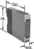
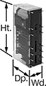
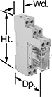
Panel-Mount Humidity Controllers
Controllers
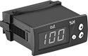 |
Controllers are SPDT (single pole, double throw). They can be set to turn one circuit from off to on (normally open) or from on to off (normally closed). Set the actuation point with the keypad.
Relative Humidity | For Panel Cutout | No. of | |||||||||||||
|---|---|---|---|---|---|---|---|---|---|---|---|---|---|---|---|
Range | Accuracy | Max. Operating Temp., ° F | Ht. | Wd. | Actuation Points | Circuits Controlled | Wire Connection | Voltage, V AC | Ht. | Wd. | Dp. | Housing Material | Each | ||
| 10% to 100% | ±1% | 158 | 1 9/64" | 2 13/16" | 2 | 1 | Screw Terminal | 120 | 1 11/32" | 3" | 2 3/8" | Plastic | 39635K44 | 0000000 | |
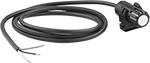
Sensors
 |
Relative Humidity | ||||||||||||
|---|---|---|---|---|---|---|---|---|---|---|---|---|
Range | Accuracy | Max. Operating Temp., ° F | Wire Connection | Wire Lead Lg. | Cable Lg., ft. | Ht. | Wd. | Housing Material | Fasteners Included | Each | ||
| 20% to 90% | ±5% | 122 | Wire Leads | 1/16" | 4 | 2 3/8" | 31/32" | Plastic | No | 39635K33 | 000000 | |
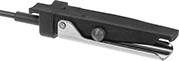
Abrasive Blaster Safety Switches
 |  |
Toggle Switch Actuator Shown in Use | Handle Actuator Shown in Use |
 | |
Trigger Actuator Shown in Use |
Electric
 |  |
Toggle Switch Actuator | Handle Actuator |
 | |
Trigger Actuator |
These switches send an electric signal to the control panel on the blaster to stop the spray. Because the signal is electric, these switches respond quickly even when your hose is long. They're recommended for hose that's over 100-ft. long and required by OSHA standards for hose that's over 200-ft. long.
Toggle Switch Actuator—Mount on top of your hose and control the toggle with your thumb. They’re smaller and lighter than switches with handle and trigger actuators, but harder to use with bulky gloves.
Handle Actuator—Mount these below your hose to grip the switch and hose together. The large surface area provides leverage when squeezing the switch in your palm, even when wearing bulky gloves.
Trigger Actuator—Extra grip allows you to twist and maneuver the hose without straining your wrist. The trigger is simple to squeeze, even when wearing bulky gloves. To prevent accidents, an included secondary safety lock requires two motions to begin blasting.
Actuator Style | Switch Starting Position | No. of Terminals | Switch Designation | Switching Current @ Voltage | Max. Voltage | Handle Material | Housing Material | Electrical Connection Type | Wire Lead Lg., ft. | NEMA Type | Wd. | Lg. | Ht. | Features | Each | ||
|---|---|---|---|---|---|---|---|---|---|---|---|---|---|---|---|---|---|
| Toggle Switch | 2 Off | 2 | SPDT | 10 amp @ 125V AC, 125V DC | 125V AC, 125V DC | — | Rubber | Hardwire | 4 | — | 2" | 4 1/16" | 2" | — | 5053N101 | 0000000 | |
| Handle | 1 Off | 3 | SPST-NC | 5 amp @ 24V DC | 28V DC | Stainless Steel | Plastic | Hardwire | 1 | — | 2 1/2" | 5" | 3" | — | 5053N14 | 000000 | |
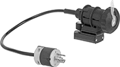
| Trigger | 1 Off and 1 On | 5 | SPST-NO | 15 amp @ 24V DC | 24V DC | Plastic | Plastic | Plug In | — | L5-15 | 1 3/4" | 8" | 8 1/2" | Hose Clamps, Secondary Safety Lock | 5053N17 | 000000 |
Air Powered
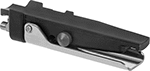 |  |
Handle Actuator | Trigger Actuator |
Send an air signal to the blaster’s inlet and outlet valves to stop the spray. These switches are easier to install and maintain than electrical switches. However, signal delay increases with hose length, so these switches are not recommended for hose over 100-ft. long.
Handle Actuator—Mount these below your hose to grip the switch and hose together. The large surface area provides leverage when squeezing the switch in your palm, even when wearing bulky gloves.
Trigger Actuator—Extra grip allows you to twist and maneuver the hose without straining your wrist. The trigger is simple to squeeze, even when wearing bulky gloves. To prevent accidents, an included secondary safety lock requires two motions to begin blasting.
Air Inlet | ||||||||||||||
|---|---|---|---|---|---|---|---|---|---|---|---|---|---|---|
Actuator Style | Switch Starting Position | Pipe Size | Gender | Thread Type | Pressure Range, psi | Handle Material | Housing Material | Wd. | Lg. | Ht. | Features | Each | ||
| Handle | 1 Off | 1/8, 1/4 | Male | NPT | 55 to 150 | Stainless Steel | Plastic | 2 1/2" | 5" | 3" | — | 5053N15 | 0000000 | |
| Trigger | 1 Off and 1 On | 1/8, 1/4 | Male | NPSM | 78 to 150 | Plastic | Plastic | 1 3/4" | 8" | 8 1/2" | Hose Clamps, Secondary Safety Lock | 5053N18 | 000000 | |
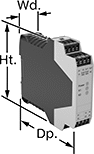
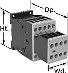
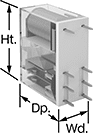
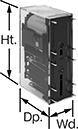
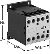
Safety Relays with Diagnostic Capabilities
 | 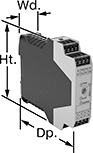 |
Relay | Relay with Time Delay |
Control and diagnose issues with safety-critical circuits. These relays have a microprocessor that monitors safety components, such as emergency stops and light curtains, and sends a signal to stop the operation if a failure is detected and restart when the issue is resolved. They also help with diagnostic tasks because of their feedback circuit, which allows basic relays to communicate their status back to the safety relay. These relays have a duplicate set of input and output signals, so they’ll still stop the controlled device if one of the inputs fails.
IP20 rated, they have recessed terminals which prevent fingers and other objects from touching live circuits. These relays have been tested to multiple safety standards and can help achieve PL, SIL, or CAT system ratings. They also meet ISO and IEC standards for machine safety.
Mount them to 35 mm DIN rail (also known as DIN 3 Rail) for fast installation.
Time Delay—Relays with delayed safety outputs are often used where power must be maintained after an input signal is received. For example, after a stop button for a machine is pressed, the guard door will stay locked until the machine cycle is finished.
No. of Terminals | Input Voltage | Switching Current @ Voltage | Max. Switching Voltage | Ht. | Wd. | Dp. | For Use With | Mounting Location | Max. System Safety Rating | Features | Each | |||
|---|---|---|---|---|---|---|---|---|---|---|---|---|---|---|
2 Circuits Controlled | ||||||||||||||
2 Off | ||||||||||||||
| 14 | 24V DC | 2 amp @ 240V AC 1.5 amp @ 24V DC | 250V AC | 4.9" | 0.69" | 4.3" | Emergency Stops, Light Curtains | DIN Rail, Surface | PLe; SIL 3; CAT IV, 250V | Auxiliary PNP Output, LED Indicator | 7774K73 | 0000000 | ||
2 Safety Outputs with 2 Off and 2 Delayed Safety Outputs with 2 Off | ||||||||||||||
| 16 | 24V DC | 3 amp @ 240V AC 3 amp @ 24V DC | 250V AC, 250V DC | 3.9" | 0.9" | 4.5" | Emergency Stops, Light Curtains | DIN Rail | PLe; SIL 3 | Time Delay | 6322N15 | 000000 | ||
2 Safety Outputs with 2 Off and 1 Signal Output with 2 On | ||||||||||||||
| 16 | 24V AC, 24V DC | 5 amp @ 240V AC 5 amp @ 24V DC | 250V AC, 250V DC | 3.9" | 0.9" | 4.5" | Two-Hand Switches | DIN Rail | PLe; SIL 3 | — | 6322N16 | 000000 | ||
3 Safety Outputs with 2 Off and 1 Signal Output with 2 On | ||||||||||||||
| 16 | 240V AC | 3 amp @ 240V AC 2.5 amp @ 24V DC | 250V AC, 250V DC | 3.9" | 1.8" | 4.5" | Emergency Stops | DIN Rail | PLe; SIL 3 | — | 6322N13 | 000000 | ||
| 24 | 24V AC, 48V AC, 120V AC, 240V AC, 24V DC, 48V DC, 60V DC, 120V DC, 240V DC | 5 amp @ 240V AC 5 amp @ 24V DC | 250V AC, 250V DC | 4.42" | 0.9" | 4.5" | Emergency Stops | DIN Rail | PLe; SIL 3 | — | 6322N14 | 00000000 | ||
3 Circuits Controlled | ||||||||||||||
3 Safety Outputs with 3 Off | ||||||||||||||
| 6 | 24V DC | 6 amp @ 240V AC 6 amp @ 24V DC | 240V AC | 3.7" | 0.9" | 4.8" | Light Curtains | DIN Rail | PLe; SIL 3 | Auxiliary PNP Output, Self-Monitoring Circuitry | 7933N23 | 000000 | ||
3 Safety Outputs with 2 Off and 1 Signal Output with 2 On | ||||||||||||||
| 16 | 24V DC | 4 amp @ 230V AC 4 amp @ 24V DC | 240V AC | 3.9" | 0.9" | 4.5" | Emergency Stops | DIN Rail | PLe; SIL 3 | — | 6322N19 | 000000 | ||
4 Circuits Controlled | ||||||||||||||
4 Off | ||||||||||||||
| 18 | 24V DC | 2 amp @ 240V AC 1.5 amp @ 24V DC | 250V AC | 4.9" | 0.89" | 4.3" | Emergency Stops, Light Curtains | DIN Rail, Surface | PLe; SIL 3; CAT IV, 250V | Auxiliary PNP Output, LED Indicator | 7774K76 | 000000 | ||
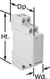
 |  |
Auxiliary Contact Block | Auxiliary Contact Block with Time Delay |
No. of Terminals | Input Voltage, V DC | Switching Current @ Voltage | Max. Switching Voltage | Ht. | Wd. | Dp. | Features | Each | |||
|---|---|---|---|---|---|---|---|---|---|---|---|
5 Safety Outputs | |||||||||||
| 16 | 24 | 3 amp @ 240V AC 2.5 amp @ 24V DC | 250V AC, 250V DC | 3.9" | 0.9" | 4.5" | — | 6322N22 | 0000000 | ||
4 Delayed Safety Outputs | |||||||||||
| 16 | 24 | 3 amp @ 240V AC 3 amp @ 24V DC | 250V AC, 250V DC | 3.9" | 0.9" | 4.5" | Time Delay | 6322N18 | 000000 | ||
Safety Relays
SIL 2, PLd Max. System Safety Rating—DIN-Rail Mount
 |
Relays that meet SIL 2 are tested for applications with a probability of failure of 0.1% to 1%. They’re often used for emergency shutdowns, and fire, gas, and overpressure detection.
No. of Terminals | Input Voltage | Control Current, mA | Switching Current @ Voltage | Max. Switching Voltage, V AC | Ht. | Wd. | Dp. | Features | Each | |||
|---|---|---|---|---|---|---|---|---|---|---|---|---|
Screw-Terminal Wire Connection | ||||||||||||
2 Circuits Controlled with 1 Off and 1 On—DPST-1NO/1NC | ||||||||||||
| 8 | 120V AC | 9 | 6 amp @ 240V AC | 250 | 3.4" | 0.9" | 3.9" | Interlocked Opposing Contacts, LED Indicator, Recessed Terminals | 6242N112 | 000000 | ||
| 8 | 24V DC | 38 | 6 amp @ 240V AC | 250 | 3.4" | 0.9" | 3.9" | Interlocked Opposing Contacts, LED Indicator, Recessed Terminals | 6242N113 | 00000 | ||
3 Circuits Controlled with 2 Off and 1 On—3PST-2NO/1NC | ||||||||||||
| 8 | 24V DC | 26 | 10 amp @ 240V AC | 250 | 3.5" | 0.7" | 2.4" | Interlocked Opposing Contacts, LED Indicator, Recessed Terminals | 6242N111 | 00000 | ||
4 Circuits Controlled with 2 Off and 2 On—4PST-2NO/2NC | ||||||||||||
| 12 | 120V AC | 10 | 6 amp @ 240V AC | 250 | 3.4" | 0.9" | 3.9" | Interlocked Opposing Contacts, LED Indicator, Recessed Terminals | 6242N114 | 000000 | ||
| 12 | 24V DC | 42 | 6 amp @ 240V AC | 250 | 3.4" | 0.9" | 3.9" | Interlocked Opposing Contacts, LED Indicator, Recessed Terminals | 6242N115 | 000000 | ||
4 Circuits Controlled with 3 Off and 1 On—4PST-3NO/1NC | ||||||||||||
| 12 | 120V AC | 10 | 6 amp @ 240V AC | 250 | 3.4" | 0.9" | 3.9" | Interlocked Opposing Contacts, LED Indicator, Recessed Terminals | 6242N116 | 000000 | ||
| 12 | 24V DC | 42 | 6 amp @ 240V AC | 250 | 3.4" | 0.9" | 3.9" | Interlocked Opposing Contacts, LED Indicator, Recessed Terminals | 6242N117 | 000000 | ||
6 Circuits Controlled with 4 Off and 2 On—6PDT-4NO/2NC | ||||||||||||
| 16 | 120V AC | 10 | 6 amp @ 240V AC | 250 | 3.4" | 0.9" | 3.9" | Interlocked Opposing Contacts, LED Indicator, Recessed Terminals | 6242N118 | 000000 | ||
| 16 | 24V DC | 42 | 6 amp @ 240V AC | 250 | 3.4" | 0.9" | 3.9" | Interlocked Opposing Contacts, LED Indicator, Recessed Terminals | 6242N119 | 000000 | ||
6 Circuits Controlled with 5 Off and 1 On—6PDT-5NO/1NC | ||||||||||||
| 16 | 24V DC | 42 | 6 amp @ 240V AC | 250 | 3.4" | 0.9" | 3.9" | Interlocked Opposing Contacts, LED Indicator, Recessed Terminals | 6242N121 | 000000 | ||
SIL 3, PLe Max. System Safety Rating—DIN-Rail Mount
 |
Relays that meet SIL 3 are tested for applications with a probability of failure of 0.01% to 0.1% and are used for preventing fires, explosions, or toxic releases.
Mirror Auxiliary Contacts—Relays with mirror auxiliary contacts have contacts that are normally closed and cannot be open at the same time as a normally open main contact.
Nondetachable Auxiliary Contacts—Relays with nondetachable contacts have auxiliary contacts that won’t separate from the relay if there is shock or vibration.
Self-Monitoring Circuitry—When a failure is detected, relays with self-monitoring circuitry signal the controller to remove power and prevent restarting until the issue is resolved.
No. of Terminals | Input Voltage | Control Current, mA | Switching Current @ Voltage | Max. Switching Voltage, V AC | Aux. Contact Switch Starting Position | Ht. | Wd. | Dp. | Features | Each | |||
|---|---|---|---|---|---|---|---|---|---|---|---|---|---|
Spring-Clamp-Terminal Wire Connection | |||||||||||||
3 Circuits Controlled with 3 Off—3PST-NO | |||||||||||||
| 18 | 24V AC, 24V DC | 5 | 5 amp @ 120V AC | 230 | 1 On | 3.9" | 0.9" | 4.8" | Interlocked Opposing Contacts, LED Indicator, Mirror Auxiliary Contacts, Nondetachable Auxiliary Contacts, Recessed Terminals, Self-Monitoring Circuitry | 6242N122 | 0000000 | ||
SIL 3, PLe, CAT IV, 600V Max. System Safety Rating—DIN-Rail and Surface Mount
 |
Relays that meet SIL 3 are tested for applications with a probability of failure of 0.01% to 0.1% and are used for preventing fires, explosions, or toxic releases.
Relays that meet CAT 4 withstand circuit surges in electrical applications up to 600V.
Mirror Auxiliary Contacts—Relays with mirror auxiliary contacts have contacts that are normally closed and cannot be open at the same time as a normally open main contact.
Nondetachable Auxiliary Contacts—Relays with nondetachable contacts have auxiliary contacts that won’t separate from the relay if there is shock or vibration.
Self-Monitoring Circuitry—When a failure is detected, relays with self-monitoring circuitry signal the controller to remove power and prevent restarting until the issue is resolved.
hp @ Switching Voltage | |||||||||||||||
|---|---|---|---|---|---|---|---|---|---|---|---|---|---|---|---|
No. of Terminals | Input Voltage | Control Current, mA | Switching Current @ Voltage | Max. Switching Voltage, V AC | Single Phase | Three Phase | Aux. Contact Switch Starting Position | Ht. | Wd. | Dp. | Features | Each | |||
Screw-Terminal Wire Connection | |||||||||||||||
3 Circuits Controlled with 3 Off—3PST-NO | |||||||||||||||
| 18 | 120V AC | 2 | 7 amp @ 400V AC | 600 | 1/4 hp @ 120V AC 1 hp @ 240V AC | 2 hp @ 240V AC 3 hp @ 480V AC 5 hp @ 600V AC | 2 Off and 3 On | 2.7" | 1.8" | 4.6" | Inspection Window, Interlocked Opposing Contacts, Mirror Auxiliary Contacts, Nondetachable Auxiliary Contacts, Recessed Terminals, Self-Monitoring Circuitry | 6242N11 | 0000000 | ||
| 18 | 120V AC | 2 | 9 amp @ 400V AC | 600 | 1/2 hp @ 120V AC 1 1/2 hp @ 240V AC | 3 hp @ 240V AC 5 hp @ 480V AC 7 1/2 hp @ 600V AC | 2 Off and 3 On | 2.7" | 1.8" | 4.6" | Inspection Window, Interlocked Opposing Contacts, Mirror Auxiliary Contacts, Nondetachable Auxiliary Contacts, Recessed Terminals, Self-Monitoring Circuitry | 6242N12 | 000000 | ||
| 18 | 120V AC | 2 | 12 amp @ 400V AC | 600 | 1 hp @ 120V AC 2 hp @ 240V AC | 3 hp @ 240V AC 10 hp @ 480V AC 10 hp @ 600V AC | 2 Off and 3 On | 2.7" | 1.8" | 4.6" | Inspection Window, Interlocked Opposing Contacts, Mirror Auxiliary Contacts, Nondetachable Auxiliary Contacts, Recessed Terminals, Self-Monitoring Circuitry | 6242N13 | 000000 | ||
| 18 | 120V AC | 5 | 18 amp @ 400V AC | 600 | 2 hp @ 120V AC 3 hp @ 240V AC | 5 hp @ 240V AC 10 hp @ 480V AC 15 hp @ 600V AC | 2 Off and 3 On | 3.4" | 1.8" | 5.5" | Inspection Window, Interlocked Opposing Contacts, Mirror Auxiliary Contacts, Nondetachable Auxiliary Contacts, Recessed Terminals, Self-Monitoring Circuitry | 6242N14 | 000000 | ||
| 18 | 120V AC | 5 | 25 amp @ 400V AC | 600 | 2 hp @ 120V AC 5 hp @ 240V AC | 10 hp @ 240V AC 15 hp @ 480V AC 20 hp @ 600V AC | 2 Off and 3 On | 3.4" | 1.8" | 5.5" | Inspection Window, Interlocked Opposing Contacts, Mirror Auxiliary Contacts, Nondetachable Auxiliary Contacts, Recessed Terminals, Self-Monitoring Circuitry | 6242N19 | 000000 | ||
| 18 | 24V DC | 3 | 18 amp @ 400V AC | 600 | 2 hp @ 120V AC 3 hp @ 240V AC | 5 hp @ 240V AC 10 hp @ 480V AC 15 hp @ 600V AC | 2 Off and 3 On | 3.4" | 1.8" | 5.5" | Inspection Window, Interlocked Opposing Contacts, Mirror Auxiliary Contacts, Nondetachable Auxiliary Contacts, Recessed Terminals, Self-Monitoring Circuitry | 6242N18 | 000000 | ||
| 18 | 24V DC | 3 | 25 amp @ 400V AC | 600 | 2 hp @ 120V AC 5 hp @ 240V AC | 10 hp @ 240V AC 15 hp @ 480V AC 20 hp @ 600V AC | 2 Off and 3 On | 3.4" | 1.8" | 5.5" | Inspection Window, Interlocked Opposing Contacts, Mirror Auxiliary Contacts, Nondetachable Auxiliary Contacts, Recessed Terminals, Self-Monitoring Circuitry | 6242N21 | 000000 | ||
| 18 | 24V DC | 12 | 7 amp @ 400V AC | 600 | 1/4 hp @ 120V AC 1 hp @ 240V AC | 2 hp @ 240V AC 3 hp @ 480V AC 5 hp @ 600V AC | 2 Off and 3 On | 2.7" | 1.8" | 4.6" | Inspection Window, Interlocked Opposing Contacts, Mirror Auxiliary Contacts, Nondetachable Auxiliary Contacts, Recessed Terminals, Self-Monitoring Circuitry | 6242N15 | 000000 | ||
| 18 | 24V DC | 18 | 9 amp @ 400V AC | 600 | 1/2 hp @ 120V AC 1 1/2 hp @ 240V AC | 3 hp @ 240V AC 5 hp @ 480V AC 7 1/2 hp @ 600V AC | 2 Off and 3 On | 2.7" | 1.8" | 4.6" | Inspection Window, Interlocked Opposing Contacts, Mirror Auxiliary Contacts, Nondetachable Auxiliary Contacts, Recessed Terminals, Self-Monitoring Circuitry | 6242N16 | 000000 | ||
| 18 | 24V DC | 18 | 12 amp @ 400V AC | 600 | 1 hp @ 120V AC 2 hp @ 240V AC | 3 hp @ 240V AC 10 hp @ 480V AC 10 hp @ 600V AC | 2 Off and 3 On | 2.7" | 1.8" | 4.6" | Inspection Window, Interlocked Opposing Contacts, Mirror Auxiliary Contacts, Nondetachable Auxiliary Contacts, Recessed Terminals, Self-Monitoring Circuitry | 6242N17 | 000000 | ||
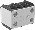
Circuit Board Safety Relays
 |  |  |
8 Terminals | 10 Terminals | 14 Terminals |
Reduce connection errors on circuit boards that control machine guards and other safety devices. Also known as force-guided contact relays, they have contact pairs that won’t close at the same time, even if contacts stick or weld shut. These relays take up less space on a board than those with electrical wiring because their solder pin terminals mount directly through circuit board holes. Use them to control high-power components, such as fans and heaters, from a low-power circuit.
Mechanical Indicator—Relays with a mechanical indicator show you whether they’re switched on or off with a flag. Peek through the window on the side to quickly check the flag’s position.
Surge Suppression Coverage—Relays with surge suppression coverage protect sensitive electronics from damage and malfunction by eliminating voltage spikes. Switching off a relay can generate surges of 300 to 500 volts, but a diode within these relays suppresses these surges. An LED indicator on these relays lights up when they’re on, so you know at a glance if they’re wired correctly.
No. of Terminals | Input Voltage, V DC | Control Current, mA | Switching Current @ Voltage | Max. Switching Voltage | Mechanical Life Cycles | Ht. | Wd. | Dp. | Pin Lg. | Features | Surge Suppression Coverage | Each | |||
|---|---|---|---|---|---|---|---|---|---|---|---|---|---|---|---|
2 Circuits Controlled with 2 Off or 2 On—DPDT | |||||||||||||||
| 8 | 12 | 59 | 8 amp @ 240V AC/24V DC | 250V AC, 125V DC | 10,000,000 | 1.1" | 0.5" | 1" | 0.2" | Interlocked Opposing Contacts | — | 6253N13 | 000000 | ||
| 8 | 24 | 29 | 3 amp @ 240V AC/24V DC | 250V AC, 125V DC | 10,000,000 | 1.1" | 0.5" | 1" | 0.16" | Interlocked Opposing Contacts, Mechanical Indicator | — | 6253N12 | 00000 | ||
| 8 | 24 | 29 | 8 amp @ 240V AC | 250V AC | 10,000,000 | 1.1" | 0.5" | 1" | 0.2" | Interlocked Opposing Contacts | — | 6253N11 | 00000 | ||
4 Circuits Controlled with 2 Off and 2 On—4PST-2NO/2NC | |||||||||||||||
| 10 | 12 | 30 | 6 amp @ 240V AC/30V DC | 250V AC, 125V DC | 10,000,000 | 1.6" | 0.5" | 1" | 0.14" | Interlocked Opposing Contacts | — | 6253N15 | 00000 | ||
| 10 | 12 | 32 | 6 amp @ 240V AC/30V DC | 250V AC, 125V DC | 10,000,000 | 1.6" | 0.5" | 1" | 0.14" | Interlocked Opposing Contacts, LED Indicator | Full | 6253N25 | 00000 | ||
| 10 | 24 | 15 | 6 amp @ 240V AC/30V DC | 250V AC, 125V DC | 10,000,000 | 1.6" | 0.5" | 1" | 0.14" | Interlocked Opposing Contacts | — | 6253N14 | 00000 | ||
| 10 | 24 | 17 | 6 amp @ 240V AC/30V DC | 250V AC, 125V DC | 10,000,000 | 1.6" | 0.5" | 1" | 0.14" | Interlocked Opposing Contacts, LED Indicator | Full | 6253N26 | 00000 | ||
4 Circuits Controlled with 3 Off and 1 On—4PST-3NO/1NC | |||||||||||||||
| 10 | 12 | 30 | 6 amp @ 240V AC/30V DC | 250V AC, 125V DC | 10,000,000 | 1.6" | 0.5" | 1" | 0.14" | Interlocked Opposing Contacts | — | 6253N16 | 00000 | ||
| 10 | 12 | 32 | 6 amp @ 240V AC/30V DC | 250V AC, 125V DC | 10,000,000 | 1.6" | 0.5" | 1" | 0.14" | Interlocked Opposing Contacts, LED Indicator | Full | 6253N27 | 00000 | ||
| 10 | 24 | 15 | 6 amp @ 240V AC/30V DC | 250V AC, 125V DC | 10,000,000 | 1.6" | 0.5" | 1" | 0.14" | Interlocked Opposing Contacts | — | 6253N17 | 00000 | ||
| 10 | 24 | 17 | 6 amp @ 240V AC/30V DC | 250V AC, 125V DC | 10,000,000 | 1.6" | 0.5" | 1" | 0.14" | Interlocked Opposing Contacts, LED Indicator | Full | 6253N28 | 00000 | ||
6 Circuits Controlled with 3 Off and 3 On—6PST-3NO/3NC | |||||||||||||||
| 14 | 12 | 41 | 6 amp @ 240V AC/30V DC | 250V AC, 125V DC | 10,000,000 | 2" | 0.5" | 1" | 0.14" | Interlocked Opposing Contacts | — | 6253N18 | 00000 | ||
| 14 | 12 | 43 | 6 amp @ 240V AC/30V DC | 250V AC, 125V DC | 10,000,000 | 2" | 0.5" | 1" | 0.14" | Interlocked Opposing Contacts, LED Indicator | Full | 6253N29 | 00000 | ||
| 14 | 24 | 20 | 6 amp @ 240V AC/30V DC | 250V AC, 125V DC | 10,000,000 | 2" | 0.5" | 1" | 0.14" | Interlocked Opposing Contacts | — | 6253N19 | 00000 | ||
| 14 | 24 | 22 | 6 amp @ 240V AC/30V DC | 250V AC, 125V DC | 10,000,000 | 2" | 0.5" | 1" | 0.14" | Interlocked Opposing Contacts, LED Indicator | Full | 6253N31 | 00000 | ||
6 Circuits Controlled with 4 Off and 2 On—6PST-4NO/2NC | |||||||||||||||
| 14 | 12 | 41 | 6 amp @ 240V AC/30V DC | 250V AC, 125V DC | 10,000,000 | 2" | 0.5" | 1" | 0.14" | Interlocked Opposing Contacts | — | 6253N21 | 00000 | ||
| 14 | 12 | 43 | 6 amp @ 240V AC/30V DC | 250V AC, 125V DC | 10,000,000 | 2" | 0.5" | 1" | 0.14" | Interlocked Opposing Contacts, LED Indicator | Full | 6253N32 | 00000 | ||
| 14 | 24 | 20 | 6 amp @ 240V AC/30V DC | 250V AC, 125V DC | 10,000,000 | 2" | 0.5" | 1" | 0.14" | Interlocked Opposing Contacts | — | 6253N22 | 00000 | ||
| 14 | 24 | 22 | 6 amp @ 240V AC/30V DC | 250V AC, 125V DC | 10,000,000 | 2" | 0.5" | 1" | 0.14" | Interlocked Opposing Contacts, LED Indicator | Full | 6253N33 | 00000 | ||
6 Circuits Controlled with 5 Off and 1 On—6PST-5NO/1NC | |||||||||||||||
| 14 | 12 | 41 | 6 amp @ 240V AC/30V DC | 250V AC, 125V DC | 10,000,000 | 2" | 0.5" | 1" | 0.14" | Interlocked Opposing Contacts | — | 6253N24 | 00000 | ||
| 14 | 12 | 43 | 6 amp @ 240V AC/30V DC | 250V AC, 125V DC | 10,000,000 | 2" | 0.5" | 1" | 0.14" | Interlocked Opposing Contacts, LED Indicator | Full | 6253N34 | 00000 | ||
| 14 | 24 | 20 | 6 amp @ 240V AC/30V DC | 250V AC, 125V DC | 10,000,000 | 2" | 0.5" | 1" | 0.14" | Interlocked Opposing Contacts | — | 6253N23 | 00000 | ||
| 14 | 24 | 22 | 6 amp @ 240V AC/30V DC | 250V AC, 125V DC | 10,000,000 | 2" | 0.5" | 1" | 0.14" | Interlocked Opposing Contacts, LED Indicator | Full | 6253N35 | 00000 | ||
High-Limit Temperature Controllers
Mechanical Relay Output
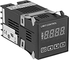 | 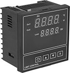 |
For 1/16 DIN Panel Cutout Size | For 1/4 DIN Panel Cutout Size |
SPDT—Controllers that are SPDT (single pole, double throw) can turn one circuit from off to on (normally open) or on to off (normally closed).
SPST-NO—Controllers that are SPST-NO (single pole, single throw) can turn one circuit from off to on (normally open).
Remote Reset—Remote-reset controllers are best for hard-to-reach locations. To operate, you’ll need to wire the remote reset input terminals, and the sensor must be below the set temperature.
Mechanical Relay | ||||||||||||||||
|---|---|---|---|---|---|---|---|---|---|---|---|---|---|---|---|---|
For Thermocouple Probe Type | Total No. of Outputs | Output Type | Switch Designation | Max. Switching Current @ Voltage | For Probe Type | Reset Type | Input Voltage Range, V AC | Ht. | Wd. | Dp. | Enclosure Rating | Features | Each | |||
For 1/16 DIN Panel Cutout Size–For 1 3/4" Ht. × 1 3/4" Wd. Panel Cutout | ||||||||||||||||
| B, C, E, J, K, L, N, PL-II, R, S, T | 1 | Heating—1 Mechanical Relay | SPDT | 2 amp @ 240V AC | Thermocouple | Manual | 90 to 264 | 1 7/8" | 1 7/8" | 3 3/4" | IP20, IP30 | Indicator Icons, Remote Reset | 5916N11 | 0000000 | ||
| B, C, E, J, K, L, N, PL-II, R, S, T | 2 | Heating—1 Mechanical Relay Heating—1 Mechanical Relay | SPDT SPST-NO | 2 amp @ 240V AC | Thermocouple | Manual | 90 to 264 | 1 7/8" | 1 7/8" | 3 3/4" | IP20, IP30 | — | 5916N13 | 000000 | ||
For 1/4 DIN Panel Cutout Size–For 3 5/8" Ht. × 3 5/8" Wd. Panel Cutout | ||||||||||||||||
| B, C, E, J, K, L, N, PL-II, R, S, T | 2 | Heating—1 Mechanical Relay Heating—1 Mechanical Relay | SPDT | 2 amp @ 240V AC | Thermocouple | Manual | 90 to 250 | 3 3/4" | 3 3/4" | 2 9/16" | IP20, IP30 | Remote Reset | 5916N12 | 000000 | ||

Interface Safety Relays
 |
These relays pair the transmission reliability of an interface relay with the fail-safe operation of a safety relay. Use them to communicate signals to devices like motors or sensors. They have interlocking contacts—also known as force-guided or mechanically linked contacts—so opposing contacts won't close at the same time. This minimizes the chance of arcing, so electricity won't jump across the contacts and interfere with your relay or system. They also have an interface that isolates input and output circuits to prevent damage from voltage spikes, reduce signal interference, and amplify signal. Mount them on 35 mm DIN rail (also known as DIN 3 rail). The relays disconnect from the socket for quick replacement.
LED Indicator—Relays with LED indicator light up when the relay is on, so you’ll know it’s wired correctly and can tell at a glance whether it’s on or off.
Safety Relays | Replacement Safety Relays | |||||||||||||||
|---|---|---|---|---|---|---|---|---|---|---|---|---|---|---|---|---|
No. of Terminals | Input Voltage, V DC | Control Current, mA | Switching Current @ Voltage | Max. Switching Voltage | hp @ Switching Voltage | Mechanical Life Cycles | Ht. | Wd. | Dp. | Features | Each | Each | ||||
2 Circuits Controlled with 1 Off and 1 On—DPST-1NO/1NC | ||||||||||||||||
| 6 | 12 | 63 | 3 amp @ 240V AC/24V DC | 250V AC, 125V DC | — | 10,000,000 | 1.1" | 0.5" | 1.1" | Interlocked Opposing Contacts, LED Indicator | 8722N12 | 000000 | 8722N13 | 000000 | ||
2 Circuits Controlled with 2 Off or 2 On—DPDT | ||||||||||||||||
| 8 | 24 | 29 | 8 amp @ 240V AC | 250V AC | 1/2 hp @ 230V AC | 10,000,000 | 3.1" | 0.6" | 2.4" | Interlocked Opposing Contacts | 8722N11 | 00000 | 6253N11 | 00000 | ||
Machine-Guard Safety Relays
 |
Relay |
The interlocked opposing contacts won't close at the same time, so these relays are suitable for safety applications such as machine guarding. The screw terminals are recessed to prevent accidental contact with live connections. Mount them on 35 mm DIN rail (also known as DIN 3 rail) or flat surfaces. These relays are built to IEC dimensional standards.
No. of Terminals | Input Voltage, V AC | Control Current, mA | Switching Current @ Voltage | Max. Switching Voltage, V AC | Mechanical Life Cycles | Ht. | Wd. | Dp. | Features | Each | |||
|---|---|---|---|---|---|---|---|---|---|---|---|---|---|
4 Circuits Controlled with 2 Off and 2 On—4PST-2NO/2NC | |||||||||||||
| 10 | 24 | 125 | 10 amp @ 600V AC | 600 | 20,000,000 | 2.3" | 1.7" | 2.2" | Interlocked Opposing Contacts, Recessed Terminals | 7230K871 | 000000 | ||
| 10 | 120 | 25 | 10 amp @ 600V AC | 600 | 20,000,000 | 2.3" | 1.7" | 2.2" | Interlocked Opposing Contacts, Recessed Terminals | 7230K872 | 00000 | ||
| 10 | 240 | 12.5 | 10 amp @ 600V AC | 600 | 20,000,000 | 2.3" | 1.7" | 2.2" | Interlocked Opposing Contacts, Recessed Terminals | 7230K873 | 00000 | ||
4 Circuits Controlled with 3 Off and 1 On—4PST-3NO/1NC | |||||||||||||
| 10 | 24 | 125 | 10 amp @ 600V AC | 600 | 20,000,000 | 2.3" | 1.7" | 2.2" | Interlocked Opposing Contacts, Recessed Terminals | 7230K881 | 00000 | ||
| 10 | 120 | 25 | 10 amp @ 600V AC | 600 | 20,000,000 | 2.3" | 1.7" | 2.2" | Interlocked Opposing Contacts, Recessed Terminals | 7230K882 | 00000 | ||
| 10 | 240 | 12.5 | 10 amp @ 600V AC | 600 | 20,000,000 | 2.3" | 1.7" | 2.2" | Interlocked Opposing Contacts, Recessed Terminals | 7230K883 | 00000 | ||
 |
Auxiliary Contact |
No. of Circuits Controlled | Switch Starting Position | Switch Designation | Mounting Location | For Relay Wd. | Each | ||
|---|---|---|---|---|---|---|---|
| 2 | 1 Off and 1 On | DPST-1NO/1NC | Front | 1.7" | 70255K13 | 000000 |
Bench-Top Autotuning Temperature Controllers
Controllers with 1 Control Zone and High-Limit Control
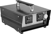 |
Controllers with high-limit control let you attach a second thermocouple probe to take the temperature of your heating equipment. If your equipment reaches the high limit, these controllers shut down your heating equipment and won't let it turn back on until you manually reset it, improving the safety of your system.
Mechanical Relay | |||||||||||||||
|---|---|---|---|---|---|---|---|---|---|---|---|---|---|---|---|
For Thermocouple Probe Type | Total No. of Outputs | Output Type | Switch Designation | Max. Switching Current @ Voltage | Reset Type | Input Voltage, V AC | NEMA Type | Cord Lg., ft. | Ht. | Wd. | Dp. | Enclosure Rating | Each | ||
| J—Heating K—High-Limit Control | 1 | Heating—1 Mechanical Relay | SPST-NO | 16 amp @ 120V AC | Automatic, Manual | 120 | 5-20 | 5 | 5" | 8 1/2" | 11" | IP50 | 1797N105 | 000000000 | |
| K—Heating K—High-Limit Control | 1 | Heating—1 Mechanical Relay | SPST-NO | 16 amp @ 120V AC | Automatic, Manual | 120 | 5-20 | 5 | 5" | 8 1/2" | 11" | IP50 | 1797N106 | 00000000 | |
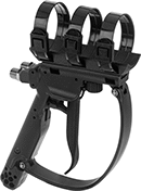
Easy-Hold Abrasive Blaster Safety Switches
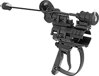
 |
Shown in Use |
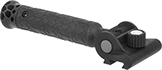
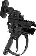
Reduce fatigue during long blasting sessions—these switches are built into a holder for your blaster hose. The holder has a brace that adjusts to shift most of the hose’s thrust away from your arms and grip, and repositions for comfort or different blasting angles. Switch easily between right- and left-hand use without having to take it apart. The housing has upper and lower rail mounts for optional accessories such as a side handle or flashlight (both sold separately). The mounts swivel around the clamp to keep accessories steady as the hose twists during blasting.
Also known as deadman switches, these switches stop blasting if you lose control. They automatically spring back to the off position to prevent injuries and reduce wasted material. To avoid accidental activation, a secondary safety lock requires an additional motion to begin blasting.
Electric
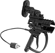 |
Trigger Actuator |
These switches send an electric signal to the control panel on the blaster to stop the spray. Because the signal is electric, these switches respond quickly even when your hose is long. They're recommended for hose that's over 100-ft. long and required by OSHA standards for hose that's over 200-ft. long.
Actuator Style | For Hose OD | Switch Starting Position | No. of Terminals | Switch Designation | Switching Current @ Voltage | Max. Voltage, V DC | Housing Material | Electrical Connection Type | NEMA Type | Wd. | Lg. | Ht. | Features | Each | ||
|---|---|---|---|---|---|---|---|---|---|---|---|---|---|---|---|---|
| Trigger | 1 3/16", 1 1/2", 1 7/8", 2 5/32" | 1 Off | 4 | SPST | 7 amp @ 12V DC 3 amp @ 24V DC | 24 | Plastic | Plug In | L5-15 | 5 1/4" | 11 3/4" | 13" | Adjustable Brace, Secondary Safety Lock, Upper and Lower Rail Mount | 8816N11 | 0000000 |
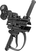
Air Powered
 |
Trigger Actuator |
Send an air signal to the blaster’s inlet and outlet valves to stop the spray. These switches are easier to install and maintain than electrical switches. However, signal delay increases with hose length, so these switches are not recommended for hose over 100-ft. long.
Air Inlet | ||||||||||||||
|---|---|---|---|---|---|---|---|---|---|---|---|---|---|---|
Actuator Style | For Hose OD | Switch Starting Position | Pipe Size | Gender | Thread Type | Pressure Range, psi | Housing Material | Wd. | Lg. | Ht. | Features | Each | ||
| Trigger | 1 3/16", 1 1/2", 1 7/8", 2 5/32" | 1 Off | 1/4 | Male | NPSM | 80 to 150 | Plastic | 5 1/4" | 11 3/4" | 13" | Adjustable Brace, Secondary Safety Lock, Upper and Lower Rail Mount | 8816N12 | 0000000 | |
