


Filter by

Mount Type

Finish

Export Control Classification Number (ECCN)
DFARS Specialty Metals
Insert Finish
Stud Finish
Actuator Style
Safety Adjustable Handles
 |  |
Threaded Stud | Threaded Hole |
Prevent unintentional changes to equipment settings—when not in use, these handles are disengaged and turn freely. To change the position, push down on the handle and turn. When you release the handle, it disengages once again. These handles are also known as clamping handles. Made of plastic, they all resist oil, grease, and solvents.
Threaded Stud
| 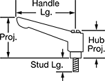 |
Thread Size | Stud Lg. | Handle Lg. | Projection | Hub Projection | Stud Material | Temp. Range, ° F | Color | Each | |||
|---|---|---|---|---|---|---|---|---|---|---|---|
Nylon | |||||||||||
| 10-32 | 3/8" | 1 5/8" | 1 3/8" | 1 1/16" | Steel | -50 to 200 | Black | 6506K11 | 00000 | ||
| 10-32 | 13/16" | 1 5/8" | 1 3/8" | 1 1/16" | Steel | -50 to 200 | Black | 6610K561 | 0000 | ||
| 1/4"-20 | 9/16" | 1 5/8" | 1 3/8" | 1 1/16" | Steel | -50 to 200 | Black | 6506K13 | 0000 | ||
| 1/4"-20 | 13/16" | 1 5/8" | 1 3/8" | 1 1/16" | Steel | -50 to 200 | Black | 6506K14 | 0000 | ||
| 1/4"-20 | 1 3/16" | 1 5/8" | 1 3/8" | 1 1/16" | Steel | -50 to 200 | Black | 6610K562 | 0000 | ||
| 5/16"-18 | 9/16" | 2 9/16" | 2" | 1 7/16" | Steel | -50 to 200 | Black | 6610K563 | 0000 | ||
| 5/16"-18 | 13/16" | 2 9/16" | 2" | 1 7/16" | Steel | -50 to 200 | Black | 6506K18 | 0000 | ||
| 5/16"-18 | 1 3/16" | 2 9/16" | 2" | 1 7/16" | Steel | -50 to 200 | Black | 6610K564 | 0000 | ||
| 5/16"-18 | 1 9/16" | 2 9/16" | 2" | 1 7/16" | Steel | -50 to 200 | Black | 6610K565 | 0000 | ||
| 3/8"-16 | 13/16" | 3 1/8" | 2 1/2" | 1 13/16" | Steel | -50 to 200 | Black | 6506K22 | 0000 | ||
| 3/8"-16 | 1 3/16" | 3 1/8" | 2 1/2" | 1 13/16" | Steel | -50 to 200 | Black | 6506K23 | 0000 | ||
| 3/8"-16 | 1 9/16" | 3 1/8" | 2 1/2" | 1 13/16" | Steel | -50 to 200 | Black | 6610K566 | 0000 | ||
| 3/8"-16 | 2" | 3 1/8" | 2 1/2" | 1 13/16" | Steel | -50 to 200 | Black | 6610K567 | 0000 | ||
| 1/2"-13 | 1 3/16" | 3 1/8" | 2 1/2" | 1 13/16" | Steel | -50 to 200 | Black | 6610K568 | 00000 | ||
| 1/2"-13 | 2" | 3 1/8" | 2 1/2" | 1 13/16" | Steel | -50 to 200 | Black | 6506K27 | 00000 | ||
| M6 x 1 mm | 10 mm | 42 mm | 35 mm | 27 mm | Steel | -50 to 200 | Black | 6610K32 | 0000 | ||
| M6 x 1 mm | 16 mm | 44 mm | 36 mm | 29 mm | Steel | -40 to 250 | Black | 6506K191 | 00000 | ||
| M6 x 1 mm | 20 mm | 42 mm | 35 mm | 27 mm | Steel | -50 to 200 | Black | 6610K33 | 0000 | ||
| M6 x 1 mm | 25 mm | 44 mm | 36 mm | 29 mm | Steel | -40 to 250 | Black | 6506K192 | 00000 | ||
| M8 x 1.25 mm | 15 mm | 65 mm | 50 mm | 36 mm | Steel | -50 to 200 | Black | 6610K35 | 0000 | ||
| M8 x 1.25 mm | 20 mm | 63 mm | 48 mm | 37 mm | Steel | -40 to 250 | Black | 6506K193 | 00000 | ||
| M8 x 1.25 mm | 20 mm | 65 mm | 50 mm | 36 mm | Steel | -50 to 200 | Black | 6610K36 | 0000 | ||
| M8 x 1.25 mm | 30 mm | 63 mm | 48 mm | 37 mm | Steel | -40 to 250 | Black | 6506K194 | 00000 | ||
| M8 x 1.25 mm | 30 mm | 65 mm | 50 mm | 36 mm | Steel | -50 to 200 | Black | 6506K181 | 0000 | ||
| M10 x 1.5 mm | 20 mm | 80 mm | 63 mm | 46 mm | Steel | -50 to 200 | Black | 6506K182 | 0000 | ||
| M10 x 1.5 mm | 30 mm | 80 mm | 63 mm | 46 mm | Steel | -50 to 200 | Black | 6610K39 | 0000 | ||
| M10 x 1.5 mm | 40 mm | 80 mm | 63 mm | 46 mm | Steel | -50 to 200 | Black | 6506K183 | 00000 | ||
| M12 x 1.75 mm | 30 mm | 80 mm | 63 mm | 46 mm | Steel | -50 to 200 | Black | 6506K184 | 00000 | ||
| M12 x 1.75 mm | 40 mm | 80 mm | 63 mm | 46 mm | Steel | -50 to 200 | Black | 6610K43 | 00000 | ||
Threaded Hole
| 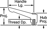 |
Thread | |||||||||||
|---|---|---|---|---|---|---|---|---|---|---|---|
Size | Dp. | Handle Lg. | Projection | Hub Projection | Insert Material | Temp. Range, ° F | Color | Each | |||
Nylon | |||||||||||
| 10-24 | 3/8" | 1 5/8" | 1 3/8" | 1 1/16" | Zinc-Plated Steel | -50 to 200 | Black | 6610K569 | 00000 | ||
| 10-32 | 3/8" | 1 5/8" | 1 3/8" | 1 1/16" | Zinc-Plated Steel | -50 to 200 | Black | 6506K41 | 0000 | ||
| 1/4"-20 | 3/8" | 1 5/8" | 1 3/8" | 1 1/16" | Zinc-Plated Steel | -50 to 200 | Black | 6506K42 | 0000 | ||
| 1/4"-20 | 3/8" | 1 3/4" | 1 7/16" | 1 1/8" | Black-Oxide Steel | -40 to 250 | Black | 6610K571 | 00000 | ||
| 1/4"-20 | 1/2" | 2 9/16" | 2" | 1 7/16" | Zinc-Plated Steel | -50 to 200 | Black | 6610K57 | 0000 | ||
| 5/16"-18 | 1/2" | 2 1/2" | 1 7/8" | 1 7/16" | Black-Oxide Steel | -40 to 250 | Black | 6610K572 | 00000 | ||
| 5/16"-18 | 1/2" | 2 9/16" | 2" | 1 7/16" | Zinc-Plated Steel | -50 to 200 | Black | 6506K44 | 0000 | ||
| 3/8"-16 | 11/16" | 3 1/8" | 2 1/2" | 1 13/16" | Zinc-Plated Steel | -50 to 200 | Black | 6506K45 | 0000 | ||
| 1/2"-13 | 11/16" | 3 1/8" | 2 1/2" | 1 13/16" | Zinc-Plated Steel | -50 to 200 | Black | 6506K46 | 0000 | ||
| M4 x 0.7 mm | 10 mm | 44 mm | 36 mm | 29 mm | Black-Oxide Steel | -40 to 250 | Black | 6506K186 | 00000 | ||
| M5 x 0.8 mm | 9 mm | 42 mm | 35 mm | 27 mm | Zinc-Plated Steel | -50 to 200 | Black | 6506K185 | 0000 | ||
| M5 x 0.8 mm | 10 mm | 44 mm | 36 mm | 29 mm | Black-Oxide Steel | -40 to 250 | Black | 6506K187 | 00000 | ||
| M6 x 1 mm | 9 mm | 42 mm | 35 mm | 27 mm | Zinc-Plated Steel | -50 to 200 | Black | 6610K52 | 0000 | ||
| M6 x 1 mm | 10 mm | 44 mm | 36 mm | 29 mm | Black-Oxide Steel | -40 to 250 | Black | 6506K188 | 00000 | ||
| M6 x 1 mm | 13 mm | 63 mm | 48 mm | 37 mm | Black-Oxide Steel | -40 to 250 | Black | 6506K189 | 00000 | ||
| M8 x 1.25 mm | 12 mm | 65 mm | 50 mm | 36 mm | Zinc-Plated Steel | -50 to 200 | Black | 6610K54 | 0000 | ||
| M8 x 1.25 mm | 13 mm | 63 mm | 48 mm | 37 mm | Black-Oxide Steel | -40 to 250 | Black | 6506K19 | 00000 | ||
| M10 x 1.5 mm | 17 mm | 80 mm | 63 mm | 46 mm | Zinc-Plated Steel | -50 to 200 | Black | 6610K55 | 0000 | ||
| M12 x 1.75 mm | 17 mm | 80 mm | 63 mm | 46 mm | Zinc-Plated Steel | -50 to 200 | Black | 6610K56 | 0000 | ||
Abrasive Blaster Safety Switches
 | 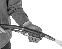 |
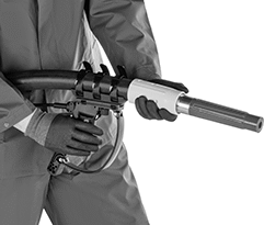
Toggle Switch Actuator Shown in Use | Handle Actuator Shown in Use |
 | |
Trigger Actuator Shown in Use |
Electric
 |  |
Toggle Switch Actuator | Handle Actuator |
 | |
Trigger Actuator |
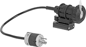
These switches send an electric signal to the control panel on the blaster to stop the spray. Because the signal is electric, these switches respond quickly even when your hose is long. They're recommended for hose that's over 100-ft. long and required by OSHA standards for hose that's over 200-ft. long.
Toggle Switch Actuator—Mount on top of your hose and control the toggle with your thumb. They’re smaller and lighter than switches with handle and trigger actuators, but harder to use with bulky gloves.
Handle Actuator—Mount these below your hose to grip the switch and hose together. The large surface area provides leverage when squeezing the switch in your palm, even when wearing bulky gloves.
Trigger Actuator—Extra grip allows you to twist and maneuver the hose without straining your wrist. The trigger is simple to squeeze, even when wearing bulky gloves. To prevent accidents, an included secondary safety lock requires two motions to begin blasting.
Actuator Style | Switch Starting Position | No. of Terminals | Switch Designation | Switching Current @ Voltage | Max. Voltage | Handle Material | Housing Material | Electrical Connection Type | Wire Lead Lg., ft. | NEMA Type | Wd. | Lg. | Ht. | Features | Each | ||
|---|---|---|---|---|---|---|---|---|---|---|---|---|---|---|---|---|---|
| Toggle Switch | 2 Off | 2 | SPDT | 10 amp @ 125V AC, 125V DC | 125V AC, 125V DC | — | Rubber | Hardwire | 4 | — | 2" | 4 1/16" | 2" | — | 5053N101 | 0000000 | |
| Handle | 1 Off | 3 | SPST-NC | 5 amp @ 24V DC | 28V DC | Stainless Steel | Plastic | Hardwire | 1 | — | 2 1/2" | 5" | 3" | — | 5053N14 | 000000 | |
| Trigger | 1 Off and 1 On | 5 | SPST-NO | 15 amp @ 24V DC | 24V DC | Plastic | Plastic | Plug In | — | L5-15 | 1 3/4" | 8" | 8 1/2" | Hose Clamps, Secondary Safety Lock | 5053N17 | 000000 |
Air Powered
 |  |
Handle Actuator | Trigger Actuator |
Send an air signal to the blaster’s inlet and outlet valves to stop the spray. These switches are easier to install and maintain than electrical switches. However, signal delay increases with hose length, so these switches are not recommended for hose over 100-ft. long.
Handle Actuator—Mount these below your hose to grip the switch and hose together. The large surface area provides leverage when squeezing the switch in your palm, even when wearing bulky gloves.
Trigger Actuator—Extra grip allows you to twist and maneuver the hose without straining your wrist. The trigger is simple to squeeze, even when wearing bulky gloves. To prevent accidents, an included secondary safety lock requires two motions to begin blasting.
Air Inlet | ||||||||||||||
|---|---|---|---|---|---|---|---|---|---|---|---|---|---|---|
Actuator Style | Switch Starting Position | Pipe Size | Gender | Thread Type | Pressure Range, psi | Handle Material | Housing Material | Wd. | Lg. | Ht. | Features | Each | ||
| Handle | 1 Off | 1/8, 1/4 | Male | NPT | 55 to 150 | Stainless Steel | Plastic | 2 1/2" | 5" | 3" | — | 5053N15 | 0000000 | |
| Trigger | 1 Off and 1 On | 1/8, 1/4 | Male | NPSM | 78 to 150 | Plastic | Plastic | 1 3/4" | 8" | 8 1/2" | Hose Clamps, Secondary Safety Lock | 5053N18 | 000000 | |
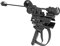
Easy-Hold Abrasive Blaster Safety Switches
 |
Shown in Use |
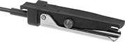
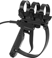
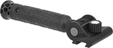
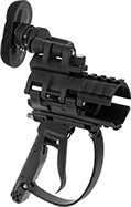
Reduce fatigue during long blasting sessions—these switches are built into a holder for your blaster hose. The holder has a brace that adjusts to shift most of the hose’s thrust away from your arms and grip, and repositions for comfort or different blasting angles. Switch easily between right- and left-hand use without having to take it apart. The housing has upper and lower rail mounts for optional accessories such as a side handle or flashlight (both sold separately). The mounts swivel around the clamp to keep accessories steady as the hose twists during blasting.
Also known as deadman switches, these switches stop blasting if you lose control. They automatically spring back to the off position to prevent injuries and reduce wasted material. To avoid accidental activation, a secondary safety lock requires an additional motion to begin blasting.
Electric
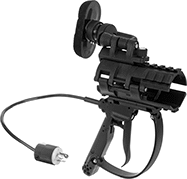 |
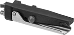
Trigger Actuator |
These switches send an electric signal to the control panel on the blaster to stop the spray. Because the signal is electric, these switches respond quickly even when your hose is long. They're recommended for hose that's over 100-ft. long and required by OSHA standards for hose that's over 200-ft. long.
Actuator Style | For Hose OD | Switch Starting Position | No. of Terminals | Switch Designation | Switching Current @ Voltage | Max. Voltage, V DC | Housing Material | Electrical Connection Type | NEMA Type | Wd. | Lg. | Ht. | Features | Each | ||
|---|---|---|---|---|---|---|---|---|---|---|---|---|---|---|---|---|
| Trigger | 1 3/16", 1 1/2", 1 7/8", 2 5/32" | 1 Off | 4 | SPST | 7 amp @ 12V DC 3 amp @ 24V DC | 24 | Plastic | Plug In | L5-15 | 5 1/4" | 11 3/4" | 13" | Adjustable Brace, Secondary Safety Lock, Upper and Lower Rail Mount | 8816N11 | 0000000 |
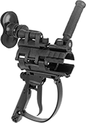
Air Powered
 |
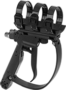
Trigger Actuator |
Send an air signal to the blaster’s inlet and outlet valves to stop the spray. These switches are easier to install and maintain than electrical switches. However, signal delay increases with hose length, so these switches are not recommended for hose over 100-ft. long.
Air Inlet | ||||||||||||||
|---|---|---|---|---|---|---|---|---|---|---|---|---|---|---|
Actuator Style | For Hose OD | Switch Starting Position | Pipe Size | Gender | Thread Type | Pressure Range, psi | Housing Material | Wd. | Lg. | Ht. | Features | Each | ||
| Trigger | 1 3/16", 1 1/2", 1 7/8", 2 5/32" | 1 Off | 1/4 | Male | NPSM | 80 to 150 | Plastic | 5 1/4" | 11 3/4" | 13" | Adjustable Brace, Secondary Safety Lock, Upper and Lower Rail Mount | 8816N12 | 0000000 | |
