


Filter by
Key Included
Actuator Style

Housing Width
Wire Connection

Switch Designation
Conduit Thread Type
Switch Starting Position
Switch Action
Number of Terminals
Specifications Met
Certification
Actuator Height
REACH
RoHS
U.S.–Mexico–Canada Agreement (USMCA) Qualifying
DFARS Specialty Metals
Export Control Classification Number (ECCN)
Frame-Mounted Safety Switches
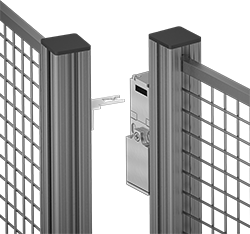 | |
Key Shown Actuating from the Side | Style B |
Also known as interlock switches, these ensure the safety of personnel by automatically shutting off power to machinery when an access door opens. Mount the switch to the door frame and mount a key to the door so that the key is inserted into the switch when the door is closed. When the door opens, the key is removed from the switch and the machine shuts down. They’re often used with machine guards for large robots.
Style B—Style A-G switches have positive-force, normally closed contacts that will open a circuit when the switch is actuated even if a spring fails or the contacts stick.
IP67 Enclosure Rating—IP67 rated switches protect against temporary submersion.
NEMA 6 Enclosure Rating—NEMA 6 rated switches protect against both temporary submersion and washdowns.
Key Included—All switches require an actuator key, but not all include one—check whether you need to pick out a separate actuator key. For some switch styles, you can also select the mounting orientation of the key.
Housing | Conduit | |||||||||||||||||
|---|---|---|---|---|---|---|---|---|---|---|---|---|---|---|---|---|---|---|
Style | No. of Circuits Controlled | Switch Starting Position | Switch Action | No. of Terminals | Switch Designation | Switching Current @ Voltage | Max. Voltage | Ht. | Wd. | Dp. | Trade Size | Thread Type | Key Included | Enclosure Rating | Each | |||
Screw-Terminal Wire Connection with Positive-Force Normally Closed Contacts | ||||||||||||||||||
| B | 2 | 1 Off and 1 On | Maintained | 4 | DPST-1NO/1NC | 5 amp @ 120V AC, 2 amp @ 24V DC | 500V AC 250V DC | 3" | 1" | 1.1" | 1/2 | NPT | Yes | IP67, NEMA 6 | 65665K32 | 0000000 | ||
Wireless Self-Powered Limit Switches
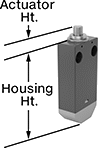 | 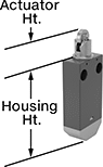 | 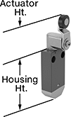 |
Style A | Style B | Style C |
 |  | |
Style D | Style E |
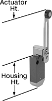
Install these limit switches where changing a battery or routing wires might be difficult—they power themselves when a moving object contacts the actuator. Place them up to 330 ft. away from the receiver (sold separately). These switches have the rapid-closing action of a snap-acting switch, but with a larger actuator.
Plunger Actuator—Plunger actuators open or close circuits when objects push against them.
Roller Plunger Actuator—Roller plunger actuators open or close circuits when an object pushes against the roller, which moves the plunger. The roller moves parallel to the mounting direction, so it helps push the plunger even if the force isn’t straight on. The roller also reduces friction during actuation which prevents wear and tear over time.
Roller Lever Actuator—Roller lever actuators open or close circuits when material moves across the switch. The roller reduces friction during actuation which prevents wear and tear over time.
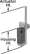
Rod Actuator—Rod actuators open or close circuits when material pushes against the rod. The rod extends from the body of the actuator, so these switches are ideal when objects actuating the switch are further away.
Housing | |||||||||||||||||
|---|---|---|---|---|---|---|---|---|---|---|---|---|---|---|---|---|---|
Style | No. of Circuits Controlled | Max. Transmission Distance, ft. | Transmission Freq., MHz | Switch Action | Actuator Material | Operating Temp. Range, ° F | Actuator Ht. | Lg. | Ht. | Dp. | Housing Material | Certification | Specs. Met | Each | |||
Plunger Actuator | |||||||||||||||||
| A | 1 | 330 | 2,405 | Momentary | Zinc Alloy | -13 to 131 | 0.4" | 1.2" | 2.5" | 0.6" | Plastic | CE Marked | IEC 60947-5, EN 60947-5 | 7786N12 | 0000000 | ||
Roller Plunger Actuator | |||||||||||||||||
| B | 1 | 330 | 2,405 | Momentary | Steel | -13 to 131 | 0.8" | 1.2" | 2.5" | 0.6" | Plastic | CE Marked | IEC 60947-5, EN 60947-5 | 7786N13 | 000000 | ||
Roller Lever Actuator | |||||||||||||||||
| C | 1 | 330 | 2,405 | Momentary | Plastic | -13 to 131 | 1.7" | 1.2" | 2.5" | 0.6" | Plastic | CE Marked | IEC 60947-5, EN 60947-5 | 7786N14 | 000000 | ||
| C | 1 | 330 | 2,405 | Momentary | Steel | -13 to 131 | 1.7" | 1.2" | 2.5" | 0.6" | Plastic | CE Marked | IEC 60947-5, EN 60947-5 | 7786N15 | 000000 | ||
| D | 1 | 330 | 2,405 | Momentary | Plastic | -13 to 131 | 1.7" to 3.6" | 1.2" | 2.5" | 0.6" | Plastic | CE Marked | IEC 60947-5, EN 60947-5 | 7786N16 | 000000 | ||
| D | 1 | 330 | 2,405 | Momentary | Plastic | -13 to 131 | 2.5" to 4.3" | 1.2" | 2.5" | 0.6" | Plastic | CE Marked | IEC 60947-5, EN 60947-5 | 7786N17 | 000000 | ||
Rod Actuator | |||||||||||||||||
| E | 1 | 330 | 2,405 | Momentary | Plastic | -13 to 131 | 3" | 1.2" | 2.5" | 0.6" | Plastic | CE Marked | IEC 60947-5, EN 60947-5 | 7786N18 | 000000 | ||
 |
No. of Outputs | Max. Transmission Distance, ft. | Transmission Freq., MHz | Max. Switching Current @ Voltage | Input Voltage, V DC | Signal Output | Mounting Location | For DIN Rail Size, mm | Wd. | Ht. | Dp. | Enclosure Rating | Certification | Specs. Met | Each | |||
|---|---|---|---|---|---|---|---|---|---|---|---|---|---|---|---|---|---|
Screw-Terminal Wire Connection | |||||||||||||||||
| 2 | 330 | 2,405 | 200 mA @ 24V DC | 24 | PNP | DIN Rail | 35 | 1 7/16" | 4 1/4" | 2 15/16" | IP20 | CE Marked | IEC 60947-5-1, IEC 60947-1, EN 60947-5-1, EN 60947-1 | 7786N19 | 0000000 | ||
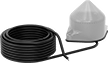 |
Use an antenna to increase the maximum transmission range to 984 ft. They also strengthen the signal if there are obstacles between your switch and receiver.
Max. Transmission Distance, ft. | Transmission Freq., MHz | Input Voltage | Cable Lg., ft. | Enclosure Rating | Certification | Each | |||
|---|---|---|---|---|---|---|---|---|---|
Wire Lead Connection | |||||||||
| 984 | 2,405 | 24V AC to 240V AC, 24V DC to 240V DC | 16 | IP65 | UL Listed, CSA Certified, CE Marked | 7786N11 | 0000000 | ||
