


Filter by
System of Measurement
Switch Starting Position

Wire Connection

Housing Material
Switch Designation
Certification
Number of Circuits Controlled
Switch Action
Electrical Connection
U.S.–Mexico–Canada Agreement (USMCA) Qualifying
Export Control Classification Number (ECCN)
DFARS Specialty Metals
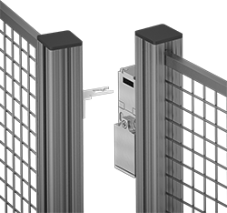
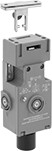
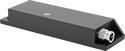
Frame-Mounted Safety Switches
 |  |  | |
Key Shown Actuating from the Side | Style C | Style D | Style G |
Housing | Conduit | ||||||||||||||||||||||||||||||||||||||||||||||||||||||||||||||||||||||||||||||||||||||||||||||||||
|---|---|---|---|---|---|---|---|---|---|---|---|---|---|---|---|---|---|---|---|---|---|---|---|---|---|---|---|---|---|---|---|---|---|---|---|---|---|---|---|---|---|---|---|---|---|---|---|---|---|---|---|---|---|---|---|---|---|---|---|---|---|---|---|---|---|---|---|---|---|---|---|---|---|---|---|---|---|---|---|---|---|---|---|---|---|---|---|---|---|---|---|---|---|---|---|---|---|---|---|
Style | No. of Circuits Controlled | Switch Starting Position | Switch Action | No. of Terminals | Switch Designation | Switching Current @ Voltage | Max. Voltage | Ht. | Wd. | Dp. | Trade Size | Thread Size | Thread Type | Key Included | Enclosure Rating | Each | |||||||||||||||||||||||||||||||||||||||||||||||||||||||||||||||||||||||||||||||||||
Screw-Terminal Wire Connection with Positive-Force Normally Closed Contacts | |||||||||||||||||||||||||||||||||||||||||||||||||||||||||||||||||||||||||||||||||||||||||||||||||||
| C | 3 | 1 Off and 2 On | Maintained | 3 | 3PST-1NO/2NC | 8 amp @ 120V AC, 4 amp @ 24V DC | 600V AC 250V DC | 3.5" | 2.1" | 1.2" | 1/2 | — | NPT | Yes | IP67 | 65665K15 | 0000000 | ||||||||||||||||||||||||||||||||||||||||||||||||||||||||||||||||||||||||||||||||||
| C | 3 | 1 Off and 2 On | Maintained | 6 | 3PST-1NO/2NC | 4 amp @ 230V AC, 4 amp @ 24V DC | 500V AC 24V DC | 3.5" | 2" | 1.2" | — | M16 | Metric | Yes | IP67 | 65665K18 | 000000 | ||||||||||||||||||||||||||||||||||||||||||||||||||||||||||||||||||||||||||||||||||
| D | 3 | 1 Off and 2 On | Maintained | 6 | 3PST-1NO/2NC | 6 amp @ 120V AC, 0.27 amp @ 24V DC | 240V AC 250V DC | 3.8" | 1.2" | 1.2" | 1/2 | — | NPT | Yes | IP67 | 65665K16 | 00000 | ||||||||||||||||||||||||||||||||||||||||||||||||||||||||||||||||||||||||||||||||||
Screw-Terminal Wire Connection with Positive-Force Normally Closed Contacts and Rotating Head | |||||||||||||||||||||||||||||||||||||||||||||||||||||||||||||||||||||||||||||||||||||||||||||||||||
| C | 3 | 1 Off and 2 On | Maintained | 6 | 3PST-1NO/2NC | 5 amp @ 120V AC, 5 amp @ 24V DC | 400V AC 400V DC | 3.5" | 2" | 1.3" | 1/2 | — | NPT | Yes | IP65 | 65665K51 | 000000 | ||||||||||||||||||||||||||||||||||||||||||||||||||||||||||||||||||||||||||||||||||
| D | 3 | 1 Off and 2 On | Maintained | 6 | 3PST-1NO/2NC | 10 amp @ 120V AC, 2.5 amp @ 125V DC | 240V AC 250V DC | 3.8" | 1.2" | 1.2" | — | M20 | Metric | No | IP67 | 65665K29 | 00000 | ||||||||||||||||||||||||||||||||||||||||||||||||||||||||||||||||||||||||||||||||||
| G | 3 | 1 Off and 2 On | Maintained | 6 | 3PST-1NO/2NC | 10 amp @ 230V AC, 4 amp @ 24V DC | 250V AC 24V DC | 4.3" | 1.6" | 1.4" | — | M20 | Metric | No | IP67 | 65665K19 | 000000 | ||||||||||||||||||||||||||||||||||||||||||||||||||||||||||||||||||||||||||||||||||
 |  |
Straight | Flexible |
Flexible—Flexible keys pivot at least 15°, making them easier to align with switches during installation.
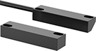
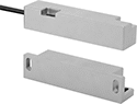
Magnetically Actuated Switches
 |  |
Style A | Style B |
 | |
Style H | Style L |
6-Pole M12 Plug |
8-Pole M12 Plug |
These switches actuate when a magnet comes within sensing distance, and reset when the magnet moves away. They’re often used to detect when a door or window opens. Mount the switch in a stationary position, such as a door frame, and mount the magnet to a movable object, such as the door. They do not include a safety relay and cannot be used with safety-guard doors found on machinery.
M12 Connection—Switches with a M12 or M8 plug connect to cords with a socket (sold separately), allowing you to quickly connect and disconnect the switch.
LED Status Indicator—Switches with an LED status indicator let you visually confirm that it’s connected and whether it’s actuated.
NEMA 6 Enclosure Rating—NEMA 6 rated switches are protected from temporary submersion.
IP67 Enclosure Rating—IP67 rated switches protect against temporary submersion, as well as dust and dirt.
IP69 Enclosure Rating—IP69 rated switches resist high temperature washdowns and dust.
Switches | Replacement Magnets | ||||||||||||||||||||||||||||||||||||||||||||||||||||||||||||||||||||||||||||||||||||||||||||||||||
|---|---|---|---|---|---|---|---|---|---|---|---|---|---|---|---|---|---|---|---|---|---|---|---|---|---|---|---|---|---|---|---|---|---|---|---|---|---|---|---|---|---|---|---|---|---|---|---|---|---|---|---|---|---|---|---|---|---|---|---|---|---|---|---|---|---|---|---|---|---|---|---|---|---|---|---|---|---|---|---|---|---|---|---|---|---|---|---|---|---|---|---|---|---|---|---|---|---|---|---|
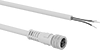
Wire Leads | |||||||||||||||||||||||||||||||||||||||||||||||||||||||||||||||||||||||||||||||||||||||||||||||||||
Style | No. of Circuits Controlled | Switch Starting Position | Switch Designation | Switching Current @ Voltage | Max. Voltage | Max. Sensing Distance | No. of | Lg., ft. | Lg. | Wd. | Ht. | Enclosure Rating | Each | Each | |||||||||||||||||||||||||||||||||||||||||||||||||||||||||||||||||||||||||||||||||||||
Plastic Housing with Wire Leads | |||||||||||||||||||||||||||||||||||||||||||||||||||||||||||||||||||||||||||||||||||||||||||||||||||
| H | 3 | 1 Off and 2 On | 3PST-1NO/2NC | 0.3 amp @ 30V DC | 30V DC | 0.47" | 6 | 16 | 2.08" | 1.1" | 0.55" | NEMA 6, IP67 | 65985K423 | 0000000 | 65985K438 | 000000 | |||||||||||||||||||||||||||||||||||||||||||||||||||||||||||||||||||||||||||||||||||
Plastic Housing with 6-Pole M12 Plug | |||||||||||||||||||||||||||||||||||||||||||||||||||||||||||||||||||||||||||||||||||||||||||||||||||
| H | 3 | 1 Off and 2 On | 3PST-1NO/2NC | 0.3 amp @ 30V DC | 30V DC | 0.47" | — | — | 2.08" | 1.1" | 0.55" | NEMA 6, IP67 | 65985K424 | 000000 | 65985K438 | 00000 | |||||||||||||||||||||||||||||||||||||||||||||||||||||||||||||||||||||||||||||||||||
Stainless Steel Housing with Wire Leads | |||||||||||||||||||||||||||||||||||||||||||||||||||||||||||||||||||||||||||||||||||||||||||||||||||
| A | 3 | 1 Off and 2 On | 3PST-1NO/2NC | 1 amp @ 30V DC | 30V DC | 0.47" | 6 | 10 | 3.11" | 1.3" | 0.63" | NEMA 6, IP67 | 65985K432 | 000000 | 65985K435 | 000000 | |||||||||||||||||||||||||||||||||||||||||||||||||||||||||||||||||||||||||||||||||||
| B | 3 | 1 Off and 2 On | 3PST-1NO/2NC | 1 amp @ 30V DC | 30V DC | 0.47" | 6 | 10 | 3.21" | 0.75" | 0.75" | NEMA 6, IP67 | 65985K428 | 000000 | 65985K437 | 000000 | |||||||||||||||||||||||||||||||||||||||||||||||||||||||||||||||||||||||||||||||||||
| H | 3 | 1 Off and 2 On | 3PST-1NO/2NC | 0.3 amp @ 30V DC | 30V DC | 0.47" | 6 | 16 | 2.08" | 1.14" | 0.53" | NEMA 6, IP67 | 65985K433 | 000000 | 65985K436 | 000000 | |||||||||||||||||||||||||||||||||||||||||||||||||||||||||||||||||||||||||||||||||||
Stainless Steel Housing with Wire Leads and LED Status Indicator | |||||||||||||||||||||||||||||||||||||||||||||||||||||||||||||||||||||||||||||||||||||||||||||||||||
| L | 3 | 1 Off and 2 On | 3PST-1NO/2NC | 10 mA @ 24V DC | 24V DC | 0.31" | 6 | 10 | 3.46" | 1.06" | 0.55" | IP69 | 65985K511 | 000000 | 65985K415 | 00000 | |||||||||||||||||||||||||||||||||||||||||||||||||||||||||||||||||||||||||||||||||||
Stainless Steel Housing with 6-Pole M12 Plug | |||||||||||||||||||||||||||||||||||||||||||||||||||||||||||||||||||||||||||||||||||||||||||||||||||
| H | 3 | 1 Off and 2 On | 3PST-1NO/2NC | 0.3 amp @ 30V DC | 30V DC | 0.47" | — | — | 2.08" | 1.14" | 0.53" | NEMA 6, IP67 | 65985K417 | 000000 | 65985K436 | 000000 | |||||||||||||||||||||||||||||||||||||||||||||||||||||||||||||||||||||||||||||||||||
Stainless Steel Housing with 8-Pole M12 Plug and LED Status Indicator | |||||||||||||||||||||||||||||||||||||||||||||||||||||||||||||||||||||||||||||||||||||||||||||||||||
| L | 3 | 1 Off and 2 On | 3PST-1NO/2NC | 10 mA @ 30V AC, 10 mA @ 30V DC | 30V AC 30V DC | 0.31" | — | — | 3.46" | 1.06" | 0.55" | IP69 | 65985K512 | 000000 | 65985K416 | 00000 | |||||||||||||||||||||||||||||||||||||||||||||||||||||||||||||||||||||||||||||||||||
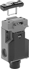
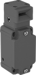
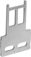
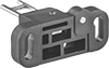
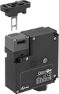
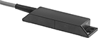
Access-Delay Frame-Mounted Safety Switches
|
Key Shown Actuating from the Side |
 |
Style A |
 |
Style B |
Delay access to hazardous areas until conditions are safe; use these switches with machines that take time to stop after they are turned off. Mount the switch to the door frame and mount the key to the door so that the key is inserted into the switch when the door is closed. When the door is pulled, the key is held in place with 225 lbs. of force until the switch receives a signal from a time-delay relay, motion sensor, or position sensor (not included) that the machine’s motion has stopped. After the motion has stopped, the key can be removed from the switch, releasing the access door. They’re often used with machine guards. All have positive-force, normally-closed contacts that will open a circuit when the switch is actuated even if a spring fails or the contacts stick. They’re rated for protection from washdowns and temporary submersion.
Styles A and B—Style A and B have a key entry on the top and side of the switch.
Housing | Conduit | ||||||||||||||||||||||||||||||||||||||||||||||||||||||||||||||||||||||||||||||||||||||||||||||||||
|---|---|---|---|---|---|---|---|---|---|---|---|---|---|---|---|---|---|---|---|---|---|---|---|---|---|---|---|---|---|---|---|---|---|---|---|---|---|---|---|---|---|---|---|---|---|---|---|---|---|---|---|---|---|---|---|---|---|---|---|---|---|---|---|---|---|---|---|---|---|---|---|---|---|---|---|---|---|---|---|---|---|---|---|---|---|---|---|---|---|---|---|---|---|---|---|---|---|---|---|
Style | No. of Circuits Controlled | Switch Starting Position | Switch Action | No. of Terminals | Switch Designation | Switching Current @ Voltage | Max. Voltage | Input Voltage | Holding Force, lbf | Ht. | Wd. | Dp. | Trade Size | Thread Type | Enclosure Rating | Each | |||||||||||||||||||||||||||||||||||||||||||||||||||||||||||||||||||||||||||||||||||
Screw-Terminal Wire Connection with Positive-Force Normally Closed Contacts | |||||||||||||||||||||||||||||||||||||||||||||||||||||||||||||||||||||||||||||||||||||||||||||||||||
| A | 3 | 1 Off and 2 On | Maintained | 6 | 3PST-1NO/2NC | 5 amp @ 120V AC, 2 amp @ 24V DC | 500V AC 250V DC | 24V AC, 24V DC | 225 | 4.7" | 2.3" | 1.4" | 1/2 | NPT | IP67, NEMA 6 | 7787K61 | 0000000 | ||||||||||||||||||||||||||||||||||||||||||||||||||||||||||||||||||||||||||||||||||
| A | 3 | 1 Off and 2 On | Maintained | 6 | 3PST-1NO/2NC | 5 amp @ 120V AC, 2 amp @ 24V DC | 500V AC 250V DC | 110V AC | 225 | 4.7" | 2.3" | 1.4" | 1/2 | NPT | IP67, NEMA 6 | 7787K62 | 000000 | ||||||||||||||||||||||||||||||||||||||||||||||||||||||||||||||||||||||||||||||||||
| B | 3 | 1 Off and 2 On | Maintained | 14 | 3PST-1NO/2NC | 3 amp @ 120V AC, 2.5 amp @ 24V DC | 240V AC 250V DC | 24V DC | 225 | 3.7" | 3.5" | 1.4" | 1/2 | NPT | IP67 | 7787K64 | 000000 | ||||||||||||||||||||||||||||||||||||||||||||||||||||||||||||||||||||||||||||||||||
Hinge-Actuated Safety Switches
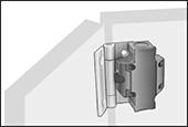 | 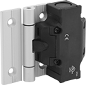 |
Replace the hinges on access doors or machine guards with these switches to keep your team safe from active machinery. Also known as interlock switches, they automatically shut off power to your machinery when the door or guard opens. They can be mounted on flat frames or aluminum T-slotted framing. These switches have positive-force, normally-closed contacts that will open a circuit when the switch is actuated, even if a spring fails or the contacts stick. They’re rated IP65 for protection from washdowns.
Overall | |||||||||||||||||||||||||||||||||||||||||||||||||||||||||||||||||||||||||||||||||||||||||||||||||||
|---|---|---|---|---|---|---|---|---|---|---|---|---|---|---|---|---|---|---|---|---|---|---|---|---|---|---|---|---|---|---|---|---|---|---|---|---|---|---|---|---|---|---|---|---|---|---|---|---|---|---|---|---|---|---|---|---|---|---|---|---|---|---|---|---|---|---|---|---|---|---|---|---|---|---|---|---|---|---|---|---|---|---|---|---|---|---|---|---|---|---|---|---|---|---|---|---|---|---|---|
For Rail Ht., mm | Mounting Hole Ctr.-to-Ctr. Wd., mm | Switch Action | No. of Terminals | Switch Designation | Switching Current @ Voltage | Wire Connection | Conduit Thread Size | Ht. | Wd. | Dp. | Each | ||||||||||||||||||||||||||||||||||||||||||||||||||||||||||||||||||||||||||||||||||||||||
3 Circuits Controlled—1 Off and 2 On | |||||||||||||||||||||||||||||||||||||||||||||||||||||||||||||||||||||||||||||||||||||||||||||||||||
4° Actuation Angle—Aluminum Hinge | |||||||||||||||||||||||||||||||||||||||||||||||||||||||||||||||||||||||||||||||||||||||||||||||||||
| 30 | 34 | Momentary | 6 | 3PST-1NO/2NC | 2 amp @ 230V AC | Screw Terminal | M20 | 5.2" | 4.39" | 1.42" | 7777K103 | 0000000 | |||||||||||||||||||||||||||||||||||||||||||||||||||||||||||||||||||||||||||||||||||||||
| 35 | 39 | Momentary | 6 | 3PST-1NO/2NC | 2 amp @ 230V AC | Screw Terminal | M20 | 5.2" | 4.39" | 1.42" | 7777K104 | 000000 | |||||||||||||||||||||||||||||||||||||||||||||||||||||||||||||||||||||||||||||||||||||||
| 40 | 44 | Momentary | 6 | 3PST-1NO/2NC | 2 amp @ 230V AC | Screw Terminal | M20 | 3.62" | 4.39" | 1.42" | 7777K48 | 000000 | |||||||||||||||||||||||||||||||||||||||||||||||||||||||||||||||||||||||||||||||||||||||
| 45 | 49 | Momentary | 6 | 3PST-1NO/2NC | 2 amp @ 230V AC | Screw Terminal | M20 | 5.2" | 4.39" | 1.42" | 7777K105 | 000000 | |||||||||||||||||||||||||||||||||||||||||||||||||||||||||||||||||||||||||||||||||||||||
4° Actuation Angle—Stainless Steel Hinge | |||||||||||||||||||||||||||||||||||||||||||||||||||||||||||||||||||||||||||||||||||||||||||||||||||
| 40 | 44 | Momentary | 6 | 3PST-1NO/2NC | 2 amp @ 230V AC | Screw Terminal | M20 | 3.62" | 4.39" | 1.42" | 7777K112 | 000000 | |||||||||||||||||||||||||||||||||||||||||||||||||||||||||||||||||||||||||||||||||||||||
8° Actuation Angle—Aluminum Hinge | |||||||||||||||||||||||||||||||||||||||||||||||||||||||||||||||||||||||||||||||||||||||||||||||||||
| 40 | 44 | Momentary | 6 | 3PST-1NO/2NC | 2 amp @ 230V AC | Screw Terminal | M20 | 3.62" | 4.39" | 1.42" | 7777K101 | 000000 | |||||||||||||||||||||||||||||||||||||||||||||||||||||||||||||||||||||||||||||||||||||||
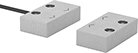
Tamper-Resistant Magnetically Actuated Switches
 |  |
Style B with Wire Leads | Style B with 4-Pole M8 Plug |
 |  |
Cords with Socket | Coded Magnet for Style B |
Prevent unauthorized use—these switches require coded magnets (sold separately) to actuate, and cannot be bypassed using ordinary magnets. They actuate when a magnet comes within sensing distance, and reset when the magnet moves away. Mount the switch in a stationary position, such as a door frame, and mount the magnet to a movable object, such as the door. They’re often used to detect when a door or window opens, and can be used with movable machine guards. All are rated IP67 for protection from temporary submersion.
Safety relays are required in safety applications with switches that control two or three circuits.
LED Status Indicator—Switches with an LED status indicator light up when they’re actuated, so you can see if they’re wired correctly with a quick glance.
Switches | Cords with Socket | Coded Magnets | |||||||||||||||||||||||||||||||||||||||||||||||||||||||||||||||||||||||||||||||||||||||||||||||||
|---|---|---|---|---|---|---|---|---|---|---|---|---|---|---|---|---|---|---|---|---|---|---|---|---|---|---|---|---|---|---|---|---|---|---|---|---|---|---|---|---|---|---|---|---|---|---|---|---|---|---|---|---|---|---|---|---|---|---|---|---|---|---|---|---|---|---|---|---|---|---|---|---|---|---|---|---|---|---|---|---|---|---|---|---|---|---|---|---|---|---|---|---|---|---|---|---|---|---|---|
Style | No. of Circuits Controlled | Switch Starting Position | Switch Designation | Switching Current @ Voltage | Max. Voltage | Input Voltage | Max. Sensing Distance | Lg. | Wd. | Ht. | Enclosure Rating | Each | Each | Mounting Hole Dia. | Each | ||||||||||||||||||||||||||||||||||||||||||||||||||||||||||||||||||||||||||||||||||||
Plastic Housing with Wire Leads | |||||||||||||||||||||||||||||||||||||||||||||||||||||||||||||||||||||||||||||||||||||||||||||||||||
| B | 3 | 1 Off and 2 On | 3PST-1NO/2NC | 10 mA @ 24V DC | 24V DC | 24V DC | 0.2" | 3.5" | 1" | 0.5" | IP67 | 7202K11 | 0000000 | ——— | 0 | 0.2" | 7202K21 | 000000 | |||||||||||||||||||||||||||||||||||||||||||||||||||||||||||||||||||||||||||||||||
| B | 3 | 1 Off and 2 On | 3PST-1NO/2NC | 0.4 amp @ 100V AC/100V DC | 100V AC 100V DC | 100V AC 100V DC | 0.2" | 3.5" | 1" | 0.5" | IP67 | 7202K33 | 000000 | ——— | 0 | 0.2" | 7202K21 | 00000 | |||||||||||||||||||||||||||||||||||||||||||||||||||||||||||||||||||||||||||||||||
Plastic Housing with 4-Pole M8 Plug and LED Status Indicator | |||||||||||||||||||||||||||||||||||||||||||||||||||||||||||||||||||||||||||||||||||||||||||||||||||
| B | 3 | 1 Off and 2 On | 3PST-1NO/2NC | 10 mA @ 24V DC | 24V DC | 24V DC | 0.2" | 3.5" | 1" | 0.5" | IP67 | 7202K32 | 000000 | 7138K15 | 000000 | 0.2" | 7202K21 | 00000 | |||||||||||||||||||||||||||||||||||||||||||||||||||||||||||||||||||||||||||||||||
Build-Your-Own Limit Switches
Switches
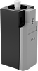 |
Screw Terminal Connection—LED Power Indicator and LED Status Indicator |
Polypropylene Housing—Switches with a polypropylene housing are lighter in weight than metal switches.
LED Power Indicator and LED Status Indicator—Switches with an LED power indicator and LED status indicator show you the status of the line and load phases. They give you extra assurance that your switch is connected and wired correctly.
IP65 Enclosure Rating—IP65 switches protect against dust and splashing water.
IP66 Enclosure Rating—IP66 switches protect against dust and washdowns.
IP67 Enclosure Rating—IP67 switches protect against dust and temporary submersion.
Housing | Conduit | ||||||||||||||||||||||||||||||||||||||||||||||||||||||||||||||||||||||||||||||||||||||||||||||||||
|---|---|---|---|---|---|---|---|---|---|---|---|---|---|---|---|---|---|---|---|---|---|---|---|---|---|---|---|---|---|---|---|---|---|---|---|---|---|---|---|---|---|---|---|---|---|---|---|---|---|---|---|---|---|---|---|---|---|---|---|---|---|---|---|---|---|---|---|---|---|---|---|---|---|---|---|---|---|---|---|---|---|---|---|---|---|---|---|---|---|---|---|---|---|---|---|---|---|---|---|
No. of Circuits Controlled | Switch Starting Position | Switch Action | Switch Designation | Switching Current @ Voltage | Max. Voltage, V DC | No. of Terminals | Lg. | Ht. | Dp. | No. of Connections | Thread Size | Enclosure Rating | Specs. Met | Certification | Each | ||||||||||||||||||||||||||||||||||||||||||||||||||||||||||||||||||||||||||||||||||||
Polypropylene Housing | |||||||||||||||||||||||||||||||||||||||||||||||||||||||||||||||||||||||||||||||||||||||||||||||||||
Screw Terminal Connection—LED Power Indicator and LED Status Indicator | |||||||||||||||||||||||||||||||||||||||||||||||||||||||||||||||||||||||||||||||||||||||||||||||||||
| 3 | 1 Off and 2 On | Momentary | 3PST-1NO/2NC | 3 amp @ 24V DC | 24 | 6 | 1.2" | 2.7" | 1.3" | 1 | M20 | IP65 | EN 50047 | UL Listed, C-UL Listed, CE Marked, CCC Marked | 7976N38 | 0000000 | |||||||||||||||||||||||||||||||||||||||||||||||||||||||||||||||||||||||||||||||||||
| 3 | 1 Off and 2 On | Momentary | 3PST-1NO/2NC | 3 amp @ 24V DC | 24 | 6 | 1.6" | 3.1" | 1.5" | 1 | M20 | IP66, IP67 | EN 50041 | UL Listed, C-UL Listed, CE Marked, CCC Marked | 7976N39 | 000000 | |||||||||||||||||||||||||||||||||||||||||||||||||||||||||||||||||||||||||||||||||||
