Precision Overload-Protection Spring-Loaded Torque Limiters
With zero backlash (no play), there’s no motion lost when these torque limiters transfer torque, so machines move smoothly with accurate and repeatable motion. They protect your machinery if there is a jam, emergency stop, or other overload by cutting off torque when a maximum torque is reached. They automatically resume transmitting torque once it drops below the set maximum. When they resume, they start transmitting torque from the same position where they stopped, keeping your drive and output sides in sync. They should not be used in applications that frequently exceed the set torque. You can adjust the set torque by using a spanner wrench to twist the adjustment ring.
To help you detect an overload, they have a sensor ring that moves out of place when these limiters cut off torque. Use a sensor (not included) to trigger an alarm or a shutdown when the ring moves.
They clamp evenly around your shaft for more holding power than set screws and won't damage your shaft.
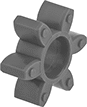
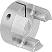
Shaft-to-shaft torque limiters also act as a flexible shaft coupling, so they compensate for angular and parallel misalignment as they regulate torque transmission between shafts. This reduces vibration and protects components from wear. For a complete unit, you’ll need a torque limiter, a hub, and a spider (all sold separately).
Through-shaft torque limiters regulate torque transmission between an input shaft and a mounted component, such as a pulley, sprocket, or gear.
![]() For technical drawings and 3-D models, click on a part number.
For technical drawings and 3-D models, click on a part number.
Torque Limiters | Spiders | ||||||||||||||
|---|---|---|---|---|---|---|---|---|---|---|---|---|---|---|---|
Torque, in.-lbs. | Hubs | Misalignment Capability | |||||||||||||
| For Shaft Dia. | Min. | Max. | OD | O'all Lg. | Each | For Shaft Dia. | Each | Max. Speed, rpm | Parallel | Angular | Temp. Range, °F | Each | |||
For Round Shafts | |||||||||||||||
| 1/4" | 9 | 25 | 1 3/8" | 2" | 0000000 | 0000000 | 0000000 | 000000 | 15,000 | 0.003" | 1° | 0° to 180° | 0000000 | 000000 | |
| 3/8" | 9 | 25 | 1 3/8" | 2" | 0000000 | 000000 | 0000000 | 00000 | 15,000 | 0.003" | 1° | 0° to 180° | 0000000 | 00000 | |
| 3/8" | 18 | 50 | 1 3/4" | 2 3/8" | 0000000 | 000000 | 0000000 | 00000 | 10,000 | 0.011" | 1° | 0° to 180° | 0000000 | 00000 | |
| 1/2" | 36 | 100 | 1 3/4" | 2 3/8" | 0000000 | 000000 | 0000000 | 00000 | 10,000 | 0.011" | 1° | 0° to 180° | 0000000 | 00000 | |
For Keyed Shafts | |||||||||||||||
| 1/2" | 90 | 220 | 2 9/16" | 3 3/8" | 0000000 | 000000 | 0000000 | 00000 | 9,000 | 0.011" | 1° | 0° to 180° | 0000000 | 00000 | |
| 5/8" | 90 | 220 | 2 9/16" | 3 3/8" | 0000000 | 000000 | 0000000 | 00000 | 9,000 | 0.011" | 1° | 0° to 180° | 0000000 | 00000 | |
| 5/8" | 225 | 705 | 2 7/8" | 3 13/16" | 0000000 | 000000 | 0000000 | 000000 | 8,000 | 0.011" | 1° | 0° to 180° | 0000000 | 00000 | |
| 3/4" | 90 | 220 | 2 9/16" | 3 3/8" | 0000000 | 000000 | 0000000 | 00000 | 9,000 | 0.011" | 1° | 0° to 180° | 0000000 | 00000 | |
| 3/4" | 225 | 705 | 2 7/8" | 3 13/16" | 0000000 | 000000 | 0000000 | 000000 | 8,000 | 0.011" | 1° | 0° to 180° | 0000000 | 00000 | |
| 1" | 225 | 705 | 2 7/8" | 3 13/16" | 0000000 | 000000 | 0000000 | 000000 | 8,000 | 0.011" | 1° | 0° to 180° | 0000000 | 00000 | |
| 1" | 710 | 1,590 | 3 5/8" | 4 3/16" | 0000000 | 00000000 | 0000000 | 000000 | 7,000 | 0.011" | 1° | 0° to 180° | 0000000 | 00000 | |
| 1 1/4" | 710 | 1,590 | 3 5/8" | 4 3/16" | 0000000 | 00000000 | 0000000 | 000000 | 7,000 | 0.011" | 1° | 0° to 180° | 0000000 | 00000 | |
Torque, in.-lbs. | ||||||||||
|---|---|---|---|---|---|---|---|---|---|---|
| For Shaft Dia. | Min. | Max. | Max. Speed, rpm | OD | Overall Lg. | Keyway Wd. × Keyway Dp. | Material | Drive Direction | Each | |
For Round Shafts | ||||||||||
| 1/4" | 1.8 | 13 | 10,000 | 1 1/4" | 1 1/8" | __ | Steel | Clockwise and Counterclockwise | 0000000 | 0000000 |
| 1/4" | 18 | 39 | 9,000 | 1 9/16" | 1 1/4" | __ | Steel | Clockwise and Counterclockwise | 0000000 | 000000 |
| 3/8" | 18 | 39 | 9,000 | 1 9/16" | 1 1/4" | __ | Steel | Clockwise and Counterclockwise | 0000000 | 000000 |
| 3/8" | 45 | 130 | 8,000 | 2 3/16" | 1 9/16" | __ | Steel | Clockwise and Counterclockwise | 0000000 | 000000 |
| 1/2" | 36 | 105 | 8,000 | 2" | 1 9/16" | __ | Steel | Clockwise and Counterclockwise | 0000000 | 000000 |
For Keyed Shafts | ||||||||||
| 1/2" | 90 | 265 | 6,000 | 2 9/16" | 2" | 1/8" × 1/16" | Steel | Clockwise and Counterclockwise | 0000000 | 000000 |
| 5/8" | 90 | 265 | 6,000 | 2 9/16" | 2" | 3/16" × 3/32" | Steel | Clockwise and Counterclockwise | 0000000 | 000000 |
| 5/8" | 180 | 615 | 4,000 | 3 5/8" | 2 5/16" | 3/16" × 3/32" | Steel | Clockwise and Counterclockwise | 0000000 | 000000 |
| 3/4" | 90 | 265 | 6,000 | 2 9/16" | 2" | 3/16" × 3/32" | Steel | Clockwise and Counterclockwise | 0000000 | 000000 |
| 3/4" | 225 | 705 | 6,000 | 2 7/8" | 2 1/8" | 3/16" × 3/32" | Steel | Clockwise and Counterclockwise | 0000000 | 000000 |
| 1" | 400 | 1,325 | 4,000 | 3 5/8" | 2 5/16" | 1/4" × 1/8" | Steel | Clockwise and Counterclockwise | 0000000 | 000000 |
| 1 1/4" | 710 | 1,990 | 4,000 | 3 5/8" | 2 5/16" | 1/4" × 1/8" | Steel | Clockwise and Counterclockwise | 0000000 | 000000 |
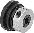
Overload-Protection Spring-Loaded Torque Limiters
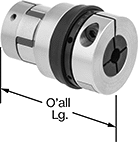
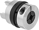
Protect your machinery if there is a jam, emergency stop, or other overload by cutting off torque between shafts when a maximum torque is reached. These torque limiters automatically resume transmitting torque once it drops below the set maximum. They should not be used in applications that frequently exceed the maximum torque. Since they come factory-set to a maximum torque, there’s no adjustment required and no risk of unintended changes to the torque setting.
They act as a flexible shaft coupling, so they reduce vibration and protect components from wear by compensating for angular and parallel misalignment. Fasten to your shafts by tightening the set screws, which bite into each shaft to hold it.
Sensor rings help you detect an overload by moving only when the limiter is transmitting torque. Use a sensor (not included) to trigger an alarm or shut down when the ring stops moving.
![]() For technical drawings and 3-D models, click on a part number.
For technical drawings and 3-D models, click on a part number.

Misalignment Capability | ||||||||||||||
|---|---|---|---|---|---|---|---|---|---|---|---|---|---|---|
| For Shaft Dia. | For Shaft Type | Max. Speed, rpm | Parallel | Angular | OD | Overall Lg. | Keyway Wd. × Keyway Dp. | Material | Center Material | Drive Direction | Re-Engagement Position | Choose a Max. Torque, in.-lbs. | Each | |
| 1/2" | Round | 1,800 | 0.031" | 6° | 3 1/2" | 3" | __ | 6061 Aluminum | Steel | Clockwise and Counterclockwise | Multiple Position | 0000000 | 000000 | |
| 5/8" | Keyed | 1,800 | 0.031" | 6° | 3 1/2" | 3" | 3/16" × 3/32" | 6061 Aluminum | Steel | Clockwise and Counterclockwise | Multiple Position | 0000000 | 00000 | |
| 3/4" | Keyed | 1,800 | 0.031" | 6° | 3 1/2" | 3" | 3/16" × 3/32" | 6061 Aluminum | Steel | Clockwise and Counterclockwise | Multiple Position | 0000000 | 00000 | |
| 7/8" | Keyed | 1,800 | 0.031" | 6° | 3 1/2" | 3" | 3/16" × 3/32" | 6061 Aluminum | Steel | Clockwise and Counterclockwise | Multiple Position | 0000000 | 00000 | |
| 1" | Keyed | 1,800 | 0.031" | 6° | 3 1/2" | 3" | 1/4" × 1/8" | 6061 Aluminum | Steel | Clockwise and Counterclockwise | Multiple Position | 0000000 | 00000 | |

with Sensor
Ring Installed

| Material | OD | Thickness | Each | |
| Steel | 3 1/2" | 0.06" | 000000 | 000000 |
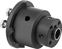
Corrosion-Resistant Overload-Protection Spring-Loaded Torque Limiters
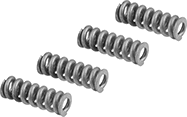
Prevent corrosion from interfering with these torque limiters’ ability to protect your machinery if there’s a jam, emergency stop, or other overload. Made of nylon, they won’t rust or corrode from moisture, salt, and oil. They cut off torque when they reach the set maximum torque and automatically resume transmitting torque once it drops below the set maximum. They should not be used in applications that frequently exceed the set torque. You can adjust the set torque by tightening the hex head screw on the housing.
To help you detect an overload, these torque limiters have a sensor ring that moves out of place when these limiters cut off torque. Use a sensor (not included) to trigger an alarm or a shutdown when the ring moves.
Fasten them to your shaft by tightening the set screws, which bite into the shaft to hold it.
Shaft-to-shaft torque limiters also act as a shaft coupling, allowing you to regulate torque transmission between two shafts.
Through-shaft torque limiters regulate torque transmission between an input shaft and a mounted component, such as a pulley, sprocket, or gear.
Spring kits let you change the torque range on your torque limiter.
![]() For technical drawings and 3-D models, click on a part number.
For technical drawings and 3-D models, click on a part number.
Torque | Misalignment Capability | |||||||||||||||
|---|---|---|---|---|---|---|---|---|---|---|---|---|---|---|---|---|
| For Shaft Dia. | For Shaft Type | Min., in.-lbs. | Max., in.-lbs. | Max. Speed, rpm | Parallel | Angular | OD | Overall Lg. | Keyway Wd. × Keyway Dp. | No. of Springs | Material | Drive Direction | Re-Engagement Position | Features | Each | |
Shaft-to-Shaft | ||||||||||||||||
| 1/4" | Round | 4 | 60 | 1,800 | 0.01" | 1° | 2 1/2" | 2 1/2" | __ | 4 | Nylon Plastic | Clockwise and Counterclockwise | Multiple Position | Sensor Ring | 00000000 | 0000000 |
| 3/8" | Round | 4 | 60 | 1,800 | 0.01" | 1° | 2 1/2" | 2 1/2" | __ | 4 | Nylon Plastic | Clockwise and Counterclockwise | Multiple Position | Sensor Ring | 00000000 | 000000 |
| 1/2" | Keyed | 4 | 60 | 1,800 | 0.01" | 1° | 2 1/2" | 2 1/2" | 1/8" × 1/16" | 4 | Nylon Plastic | Clockwise and Counterclockwise | Multiple Position | Sensor Ring | 00000000 | 000000 |
| 1/2" | Keyed | 40 | 150 | 1,800 | 0.01" | 1° | 4 1/32" | 3 7/16" | 1/8" × 1/16" | 6 | Nylon Plastic | Clockwise and Counterclockwise | Multiple Position | Sensor Ring | 00000000 | 000000 |
| 5/8" | Keyed | 40 | 150 | 1,800 | 0.01" | 1° | 4 1/32" | 3 7/16" | 3/16" × 3/32" | 6 | Nylon Plastic | Clockwise and Counterclockwise | Multiple Position | Sensor Ring | 00000000 | 000000 |
| 3/4" | Keyed | 40 | 150 | 1,800 | 0.01" | 1° | 4 1/32" | 3 7/16" | 3/16" × 3/32" | 6 | Nylon Plastic | Clockwise and Counterclockwise | Multiple Position | Sensor Ring | 00000000 | 000000 |
| 1" | Keyed | 40 | 150 | 1,800 | 0.01" | 1° | 4 1/32" | 3 7/16" | 1/4" × 1/8" | 6 | Nylon Plastic | Clockwise and Counterclockwise | Multiple Position | Sensor Ring | 00000000 | 000000 |
Through Shaft | ||||||||||||||||
| 1/4" | Round | 4 | 60 | 1,800 | __ | __ | 2 1/2" | 2 1/2" | __ | 4 | Nylon Plastic | Clockwise and Counterclockwise | Multiple Position | Sensor Ring | 00000000 | 000000 |
| 3/8" | Round | 4 | 60 | 1,800 | __ | __ | 2 1/2" | 2 1/2" | __ | 4 | Nylon Plastic | Clockwise and Counterclockwise | Multiple Position | Sensor Ring | 00000000 | 000000 |
| 1/2" | Keyed | 4 | 60 | 1,800 | __ | __ | 2 1/2" | 2 1/2" | 1/8" × 1/16" | 4 | Nylon Plastic | Clockwise and Counterclockwise | Multiple Position | Sensor Ring | 00000000 | 000000 |
| 1/2" | Keyed | 40 | 150 | 1,800 | __ | __ | 4 1/32" | 3 7/16" | 1/8" × 1/16" | 6 | Nylon Plastic | Clockwise and Counterclockwise | Multiple Position | Sensor Ring | 00000000 | 000000 |
| 5/8" | Keyed | 40 | 150 | 1,800 | __ | __ | 4 1/32" | 3 7/16" | 3/16" × 3/32" | 6 | Nylon Plastic | Clockwise and Counterclockwise | Multiple Position | Sensor Ring | 00000000 | 000000 |
| 3/4" | Keyed | 40 | 150 | 1,800 | __ | __ | 4 1/32" | 3 7/16" | 3/16" × 3/32" | 6 | Nylon Plastic | Clockwise and Counterclockwise | Multiple Position | Sensor Ring | 00000000 | 000000 |
| 1" | Keyed | 40 | 150 | 1,800 | __ | __ | 4 1/32" | 3 7/16" | 1/4" × 1/8" | 6 | Nylon Plastic | Clockwise and Counterclockwise | Multiple Position | Sensor Ring | 00000000 | 000000 |