


Filter by
Weight Capacity @ Maximum Height
Weight Capacity @ Minimum Height

Weight Capacity

DFARS Specialty Metals
Adjustment Mechanism
U.S.–Mexico–Canada Agreement (USMCA) Qualifying
Export Control Classification Number (ECCN)
REACH
RoHS
Jack Posts
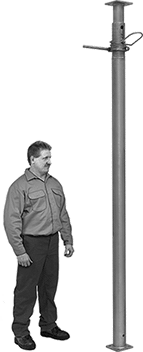 |
Support beams and joists.
Locking-Pin Adjustment—To adjust the height of locking-pin jack posts, extend the post to the approximate height needed and insert the locking pin through the hole to secure. Then turn the threaded handle counterclockwise to raise it up to 6" for more precise height adjustments.
Locking-Ring Adjustment—To adjust the height of locking-ring jack posts, slide the safety lock into the notch to secure at the approximate height needed. Then turn the 10" long handle for final height adjustments.
Ht. | Wt. Cap. | Base | Top Plate | ||||||||||||||||||||||||||||||||||||||||||||||||||||||||||||||||||||||||||||||||||||||||||||||||
|---|---|---|---|---|---|---|---|---|---|---|---|---|---|---|---|---|---|---|---|---|---|---|---|---|---|---|---|---|---|---|---|---|---|---|---|---|---|---|---|---|---|---|---|---|---|---|---|---|---|---|---|---|---|---|---|---|---|---|---|---|---|---|---|---|---|---|---|---|---|---|---|---|---|---|---|---|---|---|---|---|---|---|---|---|---|---|---|---|---|---|---|---|---|---|---|---|---|---|---|
Min. | Max. | @ Min. Ht. | @ Max. Ht. | Material | Wd. | Dp. | Wd. | Dp. | Mounting Hole Dia. (No. of) | Mounting Fasteners Included | Ctr.-to-Ctr. Adjustments | Handle Lg. | Each | ||||||||||||||||||||||||||||||||||||||||||||||||||||||||||||||||||||||||||||||||||||||
Locking-Pin Adjustment | |||||||||||||||||||||||||||||||||||||||||||||||||||||||||||||||||||||||||||||||||||||||||||||||||||
| 78" | 138" | 6,400 lb. @ 78" | 3,800 lb. @ 138" | Steel | 4 3/4" | 4 3/4" | 4 3/4" | 4 3/4" | 9/16" (8) | No | 6" | — | 2929T15 | 0000000 | |||||||||||||||||||||||||||||||||||||||||||||||||||||||||||||||||||||||||||||||||||||
| 120" | 216" | 9,300 lb. @ 120" | 2,700 lb. @ 216" | Steel | 4 3/4" | 4 3/4" | 4 3/4" | 4 3/4" | 9/16" (8) | No | 6" | — | 2929T16 | 000000 | |||||||||||||||||||||||||||||||||||||||||||||||||||||||||||||||||||||||||||||||||||||
Locking-Ring Adjustment | |||||||||||||||||||||||||||||||||||||||||||||||||||||||||||||||||||||||||||||||||||||||||||||||||||
| 16" | 24" | 18,000 lb. @ 16" | 18,000 lb. @ 24" | Steel | 4" | 4" | 4" | 4" | 3/8" (4), 5/8" (4) | No | 4" | 10" | 2946T5 | 000000 | |||||||||||||||||||||||||||||||||||||||||||||||||||||||||||||||||||||||||||||||||||||
| 25" | 41" | 18,000 lb. @ 25" | 17,000 lb. @ 41" | Steel | 4" | 4" | 4" | 4" | 3/8" (4), 5/8" (4) | No | 4" | 10" | 2946T4 | 000000 | |||||||||||||||||||||||||||||||||||||||||||||||||||||||||||||||||||||||||||||||||||||
| 40" | 64" | 18,000 lb. @ 40" | 17,000 lb. @ 64" | Steel | 4" | 4" | 4" | 4" | 3/8" (4), 5/8" (4) | No | 4" | 10" | 2946T3 | 000000 | |||||||||||||||||||||||||||||||||||||||||||||||||||||||||||||||||||||||||||||||||||||
| 68" | 100" | 17,000 lb. @ 68" | 14,000 lb. @ 100" | Steel | 4" | 4" | 4" | 4" | 3/8" (4), 5/8" (4) | No | 4" | 10" | 2946T1 | 000000 | |||||||||||||||||||||||||||||||||||||||||||||||||||||||||||||||||||||||||||||||||||||
Trench Braces
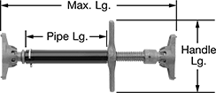 |
Support trench walls when installing pipes, cables, and other buried equipment. The ends tilt up to 10° for angular shoring and have spikes that dig into surfaces for a tight grip.
Screw the handle to adjust the length of the brace. The included pipe can be replaced with a piece of Schedule 40 pipe.
1 1/2 Pipe Size—Braces with a pipe size of 1 1/2 can accommodate pipe up to 40" long.
2 Pipe Size— Braces with a pipe size of 2 can accommodate pipe up to 50" long.
Wt. Cap., lb. | Lg. | Pipe Lg. | Pipe Size | Thread Type | Handle Lg. | Base Wd. | Base Dp. | Screw Size | Max. Wall Angle | Material | Base Material | Each | ||
|---|---|---|---|---|---|---|---|---|---|---|---|---|---|---|
| 16,000 | 18 1/2" to 25 1/2" | 10 1/2" | 1 1/2 | NPT | 9 1/2" | 3" | 6" | 1 3/8" | 10° | Steel | Iron | 2950T11 | 0000000 | |
| 16,000 | 30 1/2" to 41" | 22 1/2" | 1 1/2 | NPT | 9 1/2" | 3" | 6" | 1 3/8" | 10° | Steel | Iron | 2950T15 | 000000 | |
| 26,000 | 38" to 52" | 26" | 2 | NPT | 11" | 4 1/4" | 8" | 1 7/8" | 10° | Steel | Iron | 2950T17 | 000000 | |
| 26,000 | 50" to 64" | 38" | 2 | NPT | 11" | 4 1/4" | 8" | 1 7/8" | 10° | Steel | Iron | 2950T19 | 000000 |
