


Filter by
Mount Type


Height
Head Height
Overall Height
Length
Shoulder Diameter
DFARS Specialty Metals
Export Control Classification Number (ECCN)
Hardness
Alignment Locks
Tapered Round Alignment Locks
 |  |
Male | Female |
 |
Male |
 |
Female |
Tapered round locks prevent sliding in all directions unlike top and side locks, which only prevent sliding in one direction. Install them where the two halves of the mold meet, often called the parting line. You’ll need to machine pockets in each half of your mold separately, so you’ll need to take extra care to make sure the two pockets are aligned. For a complete pair, you’ll need a male and female lock with matching ODs. The height does not need to match.
Mounting | Male | Female | ||||||||||
|---|---|---|---|---|---|---|---|---|---|---|---|---|
OD | OD Tolerance | ID | Material | No. of Holes | For Fastener Thread Size | Fasteners Included | Choose a Height | Each | Each | |||
| 1/2" | -0.0005" to 0" | 5/16" | Steel | 1 | 10-24 | No | 11/16", 7/8", 1 3/16", 1 3/8" | 0000000 | 000000 | 0000000 | 000000 | |
| 3/4" | -0.0005" to 0" | 1/2" | Steel | 1 | 1/4"-20 | No | 11/16", 7/8", 1 3/16", 1 3/8" | 0000000 | 00000 | 0000000 | 00000 | |
| 1" | -0.0005" to 0" | 5/8" | Steel | 1 | 1/4"-20 | No | 11/16", 7/8", 1 3/16", 1 3/8" | 0000000 | 00000 | 0000000 | 00000 | |
| 1 1/2" | -0.0005" to 0" | 1" | Steel | 1 | 5/16"-18 | No | 1 1/8", 1 3/8", 1 5/8" | 0000000 | 00000 | 0000000 | 00000 | |
| 2" | -0.0005" to 0" | 1 1/2" | Steel | 1 | 5/16"-18 | No | 1 1/8", 1 3/8", 1 5/8" | 0000000 | 00000 | 0000000 | 00000 | |
No-Strike Hex-Head Alignment Pins for Flange Bolt Holes
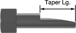 |
Body | |||||||||||||||||||||||||||||||||||||||||||||||||||||||||||||||||||||||||||||||||||||||||||||||||||
|---|---|---|---|---|---|---|---|---|---|---|---|---|---|---|---|---|---|---|---|---|---|---|---|---|---|---|---|---|---|---|---|---|---|---|---|---|---|---|---|---|---|---|---|---|---|---|---|---|---|---|---|---|---|---|---|---|---|---|---|---|---|---|---|---|---|---|---|---|---|---|---|---|---|---|---|---|---|---|---|---|---|---|---|---|---|---|---|---|---|---|---|---|---|---|---|---|---|---|---|
For Bolt Hole Dia. | Point Dia. | Taper Lg. | Overall Lg. | Shape | Texture | Each | |||||||||||||||||||||||||||||||||||||||||||||||||||||||||||||||||||||||||||||||||||||||||||||
Black-Oxide Steel | |||||||||||||||||||||||||||||||||||||||||||||||||||||||||||||||||||||||||||||||||||||||||||||||||||
| 3/8" | 1/4" | 1 3/8" | 2 1/2" | Round | Smooth | 0000000 | 000000 | ||||||||||||||||||||||||||||||||||||||||||||||||||||||||||||||||||||||||||||||||||||||||||||
| 1/2" | 3/8" | 1 1/2" | 2 7/8" | Round | Smooth | 0000000 | 00000 | ||||||||||||||||||||||||||||||||||||||||||||||||||||||||||||||||||||||||||||||||||||||||||||
| 1/2" | 3/8" | 1 1/2" | 5 7/8" | Round | Smooth | 0000000 | 00000 | ||||||||||||||||||||||||||||||||||||||||||||||||||||||||||||||||||||||||||||||||||||||||||||
| 5/8" | 1/2" | 1 3/4" | 3 3/8" | Round | Smooth | 0000000 | 00000 | ||||||||||||||||||||||||||||||||||||||||||||||||||||||||||||||||||||||||||||||||||||||||||||
| 5/8" | 1/2" | 1 3/4" | 6 3/8" | Round | Smooth | 0000000 | 00000 | ||||||||||||||||||||||||||||||||||||||||||||||||||||||||||||||||||||||||||||||||||||||||||||
| 3/4" | 5/8" | 1 7/8" | 4" | Round | Smooth | 0000000 | 00000 | ||||||||||||||||||||||||||||||||||||||||||||||||||||||||||||||||||||||||||||||||||||||||||||
| 3/4" | 5/8" | 1 7/8" | 7" | Round | Smooth | 0000000 | 00000 | ||||||||||||||||||||||||||||||||||||||||||||||||||||||||||||||||||||||||||||||||||||||||||||
| 7/8" | 5/8" | 1 15/16" | 4 1/4" | Round | Smooth | 0000000 | 00000 | ||||||||||||||||||||||||||||||||||||||||||||||||||||||||||||||||||||||||||||||||||||||||||||
| 7/8" | 11/16" | 2" | 7 1/4" | Round | Smooth | 0000000 | 00000 | ||||||||||||||||||||||||||||||||||||||||||||||||||||||||||||||||||||||||||||||||||||||||||||
| 1" | 3/4" | 2 1/4" | 4 3/4" | Round | Smooth | 0000000 | 00000 | ||||||||||||||||||||||||||||||||||||||||||||||||||||||||||||||||||||||||||||||||||||||||||||
| 1" | 3/4" | 2 1/4" | 7 3/4" | Round | Smooth | 0000000 | 000000 | ||||||||||||||||||||||||||||||||||||||||||||||||||||||||||||||||||||||||||||||||||||||||||||
| 1 1/8" | 7/8" | 2 3/4" | 6" | Round | Smooth | 0000000 | 00000 | ||||||||||||||||||||||||||||||||||||||||||||||||||||||||||||||||||||||||||||||||||||||||||||
| 1 1/8" | 7/8" | 2 3/4" | 9" | Round | Smooth | 0000000 | 000000 | ||||||||||||||||||||||||||||||||||||||||||||||||||||||||||||||||||||||||||||||||||||||||||||
| 1 1/4" | 1" | 3" | 6 1/2" | Round | Smooth | 0000000 | 000000 | ||||||||||||||||||||||||||||||||||||||||||||||||||||||||||||||||||||||||||||||||||||||||||||
| 1 1/4" | 1" | 3" | 9 1/2" | Round | Smooth | 000000 | 000000 | ||||||||||||||||||||||||||||||||||||||||||||||||||||||||||||||||||||||||||||||||||||||||||||
| 1 3/8" | 1 3/16" | 3 3/8" | 7 1/2" | Round | Smooth | 0000000 | 000000 | ||||||||||||||||||||||||||||||||||||||||||||||||||||||||||||||||||||||||||||||||||||||||||||
| 1 3/8" | 1 3/16" | 3 3/8" | 10 1/2" | Round | Smooth | 0000000 | 000000 | ||||||||||||||||||||||||||||||||||||||||||||||||||||||||||||||||||||||||||||||||||||||||||||
| 1 1/2" | 1 1/4" | 3 1/2" | 7 3/4" | Round | Smooth | 0000000 | 000000 | ||||||||||||||||||||||||||||||||||||||||||||||||||||||||||||||||||||||||||||||||||||||||||||
| 1 1/2" | 1 1/4" | 3 1/2" | 10 3/4" | Round | Smooth | 0000000 | 000000 | ||||||||||||||||||||||||||||||||||||||||||||||||||||||||||||||||||||||||||||||||||||||||||||
| 1 5/8" | 1 3/8" | 3 7/8" | 8 3/4" | Round | Smooth | 0000000 | 000000 | ||||||||||||||||||||||||||||||||||||||||||||||||||||||||||||||||||||||||||||||||||||||||||||
| 1 5/8" | 1 3/8" | 3 7/8" | 11 3/4" | Round | Smooth | 0000000 | 000000 | ||||||||||||||||||||||||||||||||||||||||||||||||||||||||||||||||||||||||||||||||||||||||||||
Mating Locating Pins and Hole Liners
Pins
 |  | 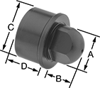 | 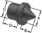 |
Tapered Head | Round Head | Diamond Head | Cone Head |
Head | Shank | Shoulder | Tolerance | ||||||||||||||||||||||||||||||||||||||||||||||||||||||||||||||||||||||||||||||||||||||||||||||||
|---|---|---|---|---|---|---|---|---|---|---|---|---|---|---|---|---|---|---|---|---|---|---|---|---|---|---|---|---|---|---|---|---|---|---|---|---|---|---|---|---|---|---|---|---|---|---|---|---|---|---|---|---|---|---|---|---|---|---|---|---|---|---|---|---|---|---|---|---|---|---|---|---|---|---|---|---|---|---|---|---|---|---|---|---|---|---|---|---|---|---|---|---|---|---|---|---|---|---|---|
Dia. (A) | Ht. (B) | Dia. (C) | Ht. (D) | Dia. | Ht. | Overall Ht. | Head Dia. | Shank Dia. | Shank Ht. | Material | Hardness | Each | |||||||||||||||||||||||||||||||||||||||||||||||||||||||||||||||||||||||||||||||||||||||
Tapered Head | |||||||||||||||||||||||||||||||||||||||||||||||||||||||||||||||||||||||||||||||||||||||||||||||||||
| 1/4" | 0.375" | 1/4" | 1/2" | 0.280" | 0.032" | 0.907" | -0.0005" to 0" | -0.0003" to 0" | — | Steel | Rockwell C50 | 000000000 | 000000 | ||||||||||||||||||||||||||||||||||||||||||||||||||||||||||||||||||||||||||||||||||||||
| 5/16" | 0.407" | 5/16" | 1/2" | 0.344" | 0.032" | 0.939" | -0.0005" to 0" | -0.0003" to 0" | — | Steel | Rockwell C50 | 000000000 | 0000 | ||||||||||||||||||||||||||||||||||||||||||||||||||||||||||||||||||||||||||||||||||||||
| 3/8" | 0.500" | 3/8" | 1/2" | 0.407" | 0.032" | 1.032" | -0.0005" to 0" | -0.0003" to 0" | — | Steel | Rockwell C50 | 000000000 | 00000 | ||||||||||||||||||||||||||||||||||||||||||||||||||||||||||||||||||||||||||||||||||||||
| 1/2" | 0.562" | 1/2" | 1/2" | 0.532" | 0.032" | 1.094" | -0.0005" to 0" | -0.0003" to 0" | — | Steel | Rockwell C50 | 000000000 | 0000 | ||||||||||||||||||||||||||||||||||||||||||||||||||||||||||||||||||||||||||||||||||||||
| 6 mm | 9.200 mm | 6 mm | — | 7.000 mm | 0.792 mm | 22.000 mm | -0.0127 mm to 0 mm | -0.00762 mm to 0 mm | — | Steel | Rockwell C58 to Rockwell C62 | 0000000 | 0000 | ||||||||||||||||||||||||||||||||||||||||||||||||||||||||||||||||||||||||||||||||||||||
| 8 mm | 10.200 mm | 8 mm | — | 9.000 mm | 0.792 mm | 23.000 mm | -0.0127 mm to 0 mm | -0.00762 mm to 0 mm | — | Steel | Rockwell C58 to Rockwell C62 | 0000000 | 0000 | ||||||||||||||||||||||||||||||||||||||||||||||||||||||||||||||||||||||||||||||||||||||
| 10 mm | 12.200 mm | 10 mm | — | 11.000 mm | 0.792 mm | 25.000 mm | -0.0127 mm to 0 mm | -0.00762 mm to 0 mm | — | Steel | Rockwell C58 to Rockwell C62 | 0000000 | 00000 | ||||||||||||||||||||||||||||||||||||||||||||||||||||||||||||||||||||||||||||||||||||||
| 12 mm | 14.200 mm | 12 mm | — | 15.000 mm | 0.792 mm | 27.000 mm | -0.0127 mm to 0 mm | -0.00762 mm to 0 mm | — | Steel | Rockwell C58 to Rockwell C62 | 0000000 | 00000 | ||||||||||||||||||||||||||||||||||||||||||||||||||||||||||||||||||||||||||||||||||||||
Round Head | |||||||||||||||||||||||||||||||||||||||||||||||||||||||||||||||||||||||||||||||||||||||||||||||||||
| 1/4" | 0.219" | 13/32" | 3/8" | 0.563" | 0.063" | 0.656" | -0.0003" to 0" | -0.0003" to 0" | — | Steel | Rockwell C50 | 00000000 | 0000 | ||||||||||||||||||||||||||||||||||||||||||||||||||||||||||||||||||||||||||||||||||||||
| 5/16" | 0.281" | 1/2" | 3/8" | 0.625" | 0.063" | 0.719" | -0.0003" to 0" | -0.0003" to 0" | — | Steel | Rockwell C50 | 00000000 | 0000 | ||||||||||||||||||||||||||||||||||||||||||||||||||||||||||||||||||||||||||||||||||||||
| 3/8" | 0.313" | 5/8" | 1/2" | 0.750" | 0.063" | 0.875" | -0.0003" to 0" | -0.0003" to 0" | — | Steel | Rockwell C50 | 00000000 | 0000 | ||||||||||||||||||||||||||||||||||||||||||||||||||||||||||||||||||||||||||||||||||||||
| 1/2" | 0.406" | 3/4" | 1/2" | 0.875" | 0.063" | 0.969" | -0.0003" to 0" | -0.0003" to 0" | — | Steel | Rockwell C50 | 00000000 | 00000 | ||||||||||||||||||||||||||||||||||||||||||||||||||||||||||||||||||||||||||||||||||||||
| 5/8" | 0.438" | 7/8" | 1/2" | 1.000" | 0.125" | 1.063" | -0.0003" to 0" | -0.0003" to 0" | — | Steel | Rockwell C50 | 00000000 | 00000 | ||||||||||||||||||||||||||||||||||||||||||||||||||||||||||||||||||||||||||||||||||||||
| 3/4" | 0.563" | 1" | 3/4" | 1.125" | 0.125" | 1.438" | -0.0003" to 0" | -0.0003" to 0" | — | Steel | Rockwell C50 | 00000000 | 00000 | ||||||||||||||||||||||||||||||||||||||||||||||||||||||||||||||||||||||||||||||||||||||
| 1" | 0.750" | 1 3/8" | 3/4" | 1.500" | 0.125" | 1.625" | -0.0003" to 0" | -0.0003" to 0" | — | Steel | Rockwell C50 | 00000000 | 00000 | ||||||||||||||||||||||||||||||||||||||||||||||||||||||||||||||||||||||||||||||||||||||
| 6 mm | 6.000 mm | 10 mm | — | 13.000 mm | 2.000 mm | 17.000 mm | -0.00762 mm to 0 mm | -0.00762 mm to 0 mm | — | Steel | Rockwell C58 to Rockwell C62 | 0000000 | 00000 | ||||||||||||||||||||||||||||||||||||||||||||||||||||||||||||||||||||||||||||||||||||||
| 8 mm | 7.000 mm | 12 mm | — | 15.000 mm | 2.000 mm | 18.000 mm | -0.00762 mm to 0 mm | -0.00762 mm to 0 mm | — | Steel | Rockwell C58 to Rockwell C62 | 0000000 | 00000 | ||||||||||||||||||||||||||||||||||||||||||||||||||||||||||||||||||||||||||||||||||||||
| 10 mm | 9.000 mm | 15 mm | — | 18.000 mm | 2.000 mm | 22.000 mm | -0.00762 mm to 0 mm | -0.00762 mm to 0 mm | — | Steel | Rockwell C58 to Rockwell C62 | 0000000 | 00000 | ||||||||||||||||||||||||||||||||||||||||||||||||||||||||||||||||||||||||||||||||||||||
| 12 mm | 10.000 mm | 18 mm | — | 22.000 mm | 2.000 mm | 23.000 mm | -0.00762 mm to 0 mm | -0.00762 mm to 0 mm | — | Steel | Rockwell C58 to Rockwell C62 | 0000000 | 00000 | ||||||||||||||||||||||||||||||||||||||||||||||||||||||||||||||||||||||||||||||||||||||
Diamond Head | |||||||||||||||||||||||||||||||||||||||||||||||||||||||||||||||||||||||||||||||||||||||||||||||||||
| 1/4" | 0.219" | 13/32" | 3/8" | 0.563" | 0.063" | 0.656" | -0.0003" to 0" | -0.0003" to 0" | — | Steel | Rockwell C50 | 00000000 | 00000 | ||||||||||||||||||||||||||||||||||||||||||||||||||||||||||||||||||||||||||||||||||||||
| 5/16" | 0.281" | 1/2" | 3/8" | 0.625" | 0.063" | 0.719" | -0.0003" to 0" | -0.0003" to 0" | — | Steel | Rockwell C50 | 00000000 | 00000 | ||||||||||||||||||||||||||||||||||||||||||||||||||||||||||||||||||||||||||||||||||||||
| 3/8" | 0.313" | 5/8" | 1/2" | 0.750" | 0.063" | 0.875" | -0.0003" to 0" | -0.0003" to 0" | — | Steel | Rockwell C50 | 00000000 | 00000 | ||||||||||||||||||||||||||||||||||||||||||||||||||||||||||||||||||||||||||||||||||||||
| 1/2" | 0.406" | 3/4" | 1/2" | 0.875" | 0.063" | 0.969" | -0.0003" to 0" | -0.0003" to 0" | — | Steel | Rockwell C50 | 00000000 | 00000 | ||||||||||||||||||||||||||||||||||||||||||||||||||||||||||||||||||||||||||||||||||||||
| 5/8" | 0.438" | 7/8" | 1/2" | 1.000" | 0.125" | 1.063" | -0.0003" to 0" | -0.0003" to 0" | — | Steel | Rockwell C50 | 00000000 | 00000 | ||||||||||||||||||||||||||||||||||||||||||||||||||||||||||||||||||||||||||||||||||||||
| 3/4" | 0.563" | 1" | 3/4" | 1.125" | 0.125" | 1.438" | -0.0003" to 0" | -0.0003" to 0" | — | Steel | Rockwell C50 | 00000000 | 00000 | ||||||||||||||||||||||||||||||||||||||||||||||||||||||||||||||||||||||||||||||||||||||
| 1" | 0.750" | 1 3/8" | 3/4" | 1.500" | 0.125" | 1.625" | -0.0003" to 0" | -0.0003" to 0" | — | Steel | Rockwell C50 | 00000000 | 00000 | ||||||||||||||||||||||||||||||||||||||||||||||||||||||||||||||||||||||||||||||||||||||
| 6 mm | 6.000 mm | 10 mm | — | 13.000 mm | 2.000 mm | 17.000 mm | -0.00762 mm to 0 mm | -0.00762 mm to 0 mm | — | Steel | Rockwell C58 to Rockwell C62 | 0000000 | 00000 | ||||||||||||||||||||||||||||||||||||||||||||||||||||||||||||||||||||||||||||||||||||||
| 8 mm | 7.000 mm | 12 mm | — | 15.000 mm | 2.000 mm | 18.000 mm | -0.00762 mm to 0 mm | -0.00762 mm to 0 mm | — | Steel | Rockwell C58 to Rockwell C62 | 0000000 | 00000 | ||||||||||||||||||||||||||||||||||||||||||||||||||||||||||||||||||||||||||||||||||||||
| 10 mm | 9.000 mm | 15 mm | — | 18.000 mm | 2.000 mm | 22.000 mm | -0.00762 mm to 0 mm | -0.00762 mm to 0 mm | — | Steel | Rockwell C58 to Rockwell C62 | 0000000 | 00000 | ||||||||||||||||||||||||||||||||||||||||||||||||||||||||||||||||||||||||||||||||||||||
| 12 mm | 10.000 mm | 18 mm | — | 22.000 mm | 2.000 mm | 23.000 mm | -0.00762 mm to 0 mm | -0.00762 mm to 0 mm | — | Steel | Rockwell C58 to Rockwell C62 | 0000000 | 00000 | ||||||||||||||||||||||||||||||||||||||||||||||||||||||||||||||||||||||||||||||||||||||
Cone Head | |||||||||||||||||||||||||||||||||||||||||||||||||||||||||||||||||||||||||||||||||||||||||||||||||||
| 7/16" | 0.313" | 1/2" | 3/8" | 0.750" | 0.188" | 0.875" | -0.0045" to 0.0055" | -0.0003" to 0" | -0.0625" to 0.0625" | Steel | Rockwell C60 to Rockwell C64 | 00000000 | 00000 | ||||||||||||||||||||||||||||||||||||||||||||||||||||||||||||||||||||||||||||||||||||||
| 11/16" | 0.500" | 3/4" | 9/16" | 1.000" | 0.188" | 1.250" | -0.0165" to -0.0065" | -0.0003" to 0" | -0.0625" to 0.0625" | Steel | Rockwell C60 to Rockwell C64 | 00000000 | 00000 | ||||||||||||||||||||||||||||||||||||||||||||||||||||||||||||||||||||||||||||||||||||||
Hole Liners
 |
Shank | Shoulder | Tolerance | |||||||||||||||||||||||||||||||||||||||||||||||||||||||||||||||||||||||||||||||||||||||||||||||||
|---|---|---|---|---|---|---|---|---|---|---|---|---|---|---|---|---|---|---|---|---|---|---|---|---|---|---|---|---|---|---|---|---|---|---|---|---|---|---|---|---|---|---|---|---|---|---|---|---|---|---|---|---|---|---|---|---|---|---|---|---|---|---|---|---|---|---|---|---|---|---|---|---|---|---|---|---|---|---|---|---|---|---|---|---|---|---|---|---|---|---|---|---|---|---|---|---|---|---|---|
For Pin Head Dia. | ID | Dia. (C) | Ht. (D) | Dia. | Ht. | Overall Ht. | Shank Dia. | Shank Ht. | ID | Material | Hardness | Each | |||||||||||||||||||||||||||||||||||||||||||||||||||||||||||||||||||||||||||||||||||||||
For Tapered-Head Pins | |||||||||||||||||||||||||||||||||||||||||||||||||||||||||||||||||||||||||||||||||||||||||||||||||||
| 1/4" | 1/4" | 1/2" | 3/8" | 0.625" | 0.094" | 0.469" | -0.0003" to 0" | 0.0014" to 0.0017" | 0" to 0.0004" | Steel | Rockwell C60 to Rockwell C64 | 000000000 | 000000 | ||||||||||||||||||||||||||||||||||||||||||||||||||||||||||||||||||||||||||||||||||||||
| 5/16" | 5/16" | 1/2" | 3/8" | 0.625" | 0.094" | 0.469" | -0.0003" to 0" | 0.0014" to 0.0017" | 0" to 0.0004" | Steel | Rockwell C60 to Rockwell C64 | 000000000 | 00000 | ||||||||||||||||||||||||||||||||||||||||||||||||||||||||||||||||||||||||||||||||||||||
| 3/8" | 3/8" | 5/8" | 1/2" | 0.750" | 0.094" | 0.594" | -0.0003" to 0" | 0.0014" to 0.0017" | 0" to 0.0004" | Steel | Rockwell C60 to Rockwell C64 | 000000000 | 00000 | ||||||||||||||||||||||||||||||||||||||||||||||||||||||||||||||||||||||||||||||||||||||
| 1/2" | 1/2" | 3/4" | 5/8" | 0.875" | 0.094" | 0.719" | -0.0003" to 0" | 0.0015" to 0.0018" | 0" to 0.0004" | Steel | Rockwell C60 to Rockwell C64 | 000000000 | 00000 | ||||||||||||||||||||||||||||||||||||||||||||||||||||||||||||||||||||||||||||||||||||||
| 6 mm | 6 mm | 10 mm | 7 mm | 13.000 mm | 3.000 mm | 10.000 mm | 0.023 mm to 0.032 mm | -0.254 mm to 0.254 mm | 0 mm to 0.0102 mm | Steel | Rockwell C58 to Rockwell C62 | 0000000 | 00000 | ||||||||||||||||||||||||||||||||||||||||||||||||||||||||||||||||||||||||||||||||||||||
| 8 mm | 8 mm | 12 mm | 7 mm | 15.000 mm | 3.000 mm | 10.000 mm | 0.028 mm to 0.039 mm | -0.254 mm to 0.254 mm | 0 mm to 0.0102 mm | Steel | Rockwell C58 to Rockwell C62 | 0000000 | 00000 | ||||||||||||||||||||||||||||||||||||||||||||||||||||||||||||||||||||||||||||||||||||||
| 10 mm | 10 mm | 15 mm | 9 mm | 18.000 mm | 3.000 mm | 12.000 mm | 0.028 mm to 0.039 mm | -0.254 mm to 0.254 mm | 0 mm to 0.0102 mm | Steel | Rockwell C58 to Rockwell C62 | 0000000 | 00000 | ||||||||||||||||||||||||||||||||||||||||||||||||||||||||||||||||||||||||||||||||||||||
| 12 mm | 12 mm | 18 mm | 12 mm | 22.000 mm | 3.000 mm | 15.000 mm | 0.028 mm to 0.039 mm | -0.254 mm to 0.254 mm | 0 mm to 0.0102 mm | Steel | Rockwell C58 to Rockwell C62 | 0000000 | 00000 | ||||||||||||||||||||||||||||||||||||||||||||||||||||||||||||||||||||||||||||||||||||||
For Diamond- and Round-Head Pins | |||||||||||||||||||||||||||||||||||||||||||||||||||||||||||||||||||||||||||||||||||||||||||||||||||
| 1/4" | 1/4" | 13/32" | 7/16" | 0.563" | 0.063" | 0.500" | -0.0003" to 0" | — | 0.0001" to 0.0005" | Steel | Rockwell C50 to Rockwell C62 | 00000000 | 00000 | ||||||||||||||||||||||||||||||||||||||||||||||||||||||||||||||||||||||||||||||||||||||
| 5/16" | 5/16" | 1/2" | 7/16" | 0.625" | 0.063" | 0.500" | -0.0003" to 0" | — | 0.0001" to 0.0005" | Steel | Rockwell C50 to Rockwell C62 | 00000000 | 00000 | ||||||||||||||||||||||||||||||||||||||||||||||||||||||||||||||||||||||||||||||||||||||
| 3/8" | 3/8" | 5/8" | 7/16" | 0.750" | 0.063" | 0.500" | -0.0003" to 0" | — | 0.0001" to 0.0005" | Steel | Rockwell C50 to Rockwell C62 | 00000000 | 00000 | ||||||||||||||||||||||||||||||||||||||||||||||||||||||||||||||||||||||||||||||||||||||
| 1/2" | 1/2" | 3/4" | 1/2" | 0.875" | 0.063" | 0.562" | -0.0003" to 0" | — | 0.0001" to 0.0005" | Steel | Rockwell C50 to Rockwell C62 | 00000000 | 00000 | ||||||||||||||||||||||||||||||||||||||||||||||||||||||||||||||||||||||||||||||||||||||
| 5/8" | 5/8" | 7/8" | 1/2" | 1.000" | 0.125" | 0.625" | -0.0003" to 0" | — | 0.0002" to 0.0006" | Steel | Rockwell C50 to Rockwell C62 | 00000000 | 00000 | ||||||||||||||||||||||||||||||||||||||||||||||||||||||||||||||||||||||||||||||||||||||
| 3/4" | 3/4" | 1" | 1/2" | 1.125" | 0.125" | 0.625" | -0.0003" to 0" | — | 0.0002" to 0.0006" | Steel | Rockwell C50 to Rockwell C62 | 00000000 | 00000 | ||||||||||||||||||||||||||||||||||||||||||||||||||||||||||||||||||||||||||||||||||||||
| 1" | 1" | 1 3/8" | 11/16" | 1.500" | 0.125" | 0.812" | -0.0003" to 0" | — | 0.0002" to 0.0006" | Steel | Rockwell C50 to Rockwell C62 | 00000000 | 00000 | ||||||||||||||||||||||||||||||||||||||||||||||||||||||||||||||||||||||||||||||||||||||
| 6 mm | 6 mm | 10 mm | 8 mm | 13.000 mm | 2.000 mm | 10.000 mm | 0.023 mm to 0.032 mm | -0.254 mm to 0.254 mm | 0 mm to 0.0102 mm | Steel | Rockwell C58 to Rockwell C62 | 0000000 | 00000 | ||||||||||||||||||||||||||||||||||||||||||||||||||||||||||||||||||||||||||||||||||||||
| 8 mm | 8 mm | 12 mm | 8 mm | 15.000 mm | 2.000 mm | 10.000 mm | 0.028 mm to 0.039 mm | -0.254 mm to 0.254 mm | 0 mm to 0.0102 mm | Steel | Rockwell C58 to Rockwell C62 | 0000000 | 00000 | ||||||||||||||||||||||||||||||||||||||||||||||||||||||||||||||||||||||||||||||||||||||
| 10 mm | 10 mm | 15 mm | 10 mm | 18.000 mm | 2.000 mm | 12.000 mm | 0.028 mm to 0.039 mm | -0.254 mm to 0.254 mm | 0 mm to 0.0102 mm | Steel | Rockwell C58 to Rockwell C62 | 0000000 | 00000 | ||||||||||||||||||||||||||||||||||||||||||||||||||||||||||||||||||||||||||||||||||||||
| 12 mm | 12 mm | 18 mm | 10 mm | 22.000 mm | 2.000 mm | 12.000 mm | 0.028 mm to 0.039 mm | -0.254 mm to 0.254 mm | 0 mm to 0.0102 mm | Steel | Rockwell C58 to Rockwell C62 | 0000000 | 00000 | ||||||||||||||||||||||||||||||||||||||||||||||||||||||||||||||||||||||||||||||||||||||
For Conical-Head Pins | |||||||||||||||||||||||||||||||||||||||||||||||||||||||||||||||||||||||||||||||||||||||||||||||||||
| 7/16" | 3/8" | 1/2" | 1/4" | 0.750" | 0.250" | 0.500" | -0.0003" to 0" | -0.0625" to 0.0625" | -0.01" to 0" | Steel | Rockwell C60 to Rockwell C64 | 00000000 | 00000 | ||||||||||||||||||||||||||||||||||||||||||||||||||||||||||||||||||||||||||||||||||||||
| 11/16" | 5/8" | 3/4" | 3/8" | 1.000" | 0.375" | 0.750" | -0.0003" to 0" | -0.0625" to 0.0625" | -0.014" to -0.004" | Steel | Rockwell C60 to Rockwell C64 | 00000000 | 00000 | ||||||||||||||||||||||||||||||||||||||||||||||||||||||||||||||||||||||||||||||||||||||
No-Strike Hex-Head Alignment Pin Sets for Flange Bolt Holes
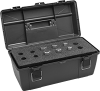 |
The tapered shaft of these pins eliminates the need for hammering and prying when aligning flange bolt holes. To align bolt holes, fit the tapered end of the pin into the bolt holes and use a wrench on the hex head to rotate and align the holes. If your bolt hole is in between the sizes listed, choose the smaller size pin.
Body | |||||||||||||||||||||||||||||||||||||||||||||||||||||||||||||||||||||||||||||||||||||||||||||||||||
|---|---|---|---|---|---|---|---|---|---|---|---|---|---|---|---|---|---|---|---|---|---|---|---|---|---|---|---|---|---|---|---|---|---|---|---|---|---|---|---|---|---|---|---|---|---|---|---|---|---|---|---|---|---|---|---|---|---|---|---|---|---|---|---|---|---|---|---|---|---|---|---|---|---|---|---|---|---|---|---|---|---|---|---|---|---|---|---|---|---|---|---|---|---|---|---|---|---|---|---|
No. of Pieces | Includes | Shape | Texture | Container Type | Each | ||||||||||||||||||||||||||||||||||||||||||||||||||||||||||||||||||||||||||||||||||||||||||||||
Black-Oxide Steel | |||||||||||||||||||||||||||||||||||||||||||||||||||||||||||||||||||||||||||||||||||||||||||||||||||
| 6 | Two 5/8" Point Dia. Pins for 3/4" Bolt Hole Dia. Two 5/8" Point Dia. Pins for 7/8" Bolt Hole Dia. Two 3/4" Point Dia. Pins for 1" Bolt Hole Dia. | Round | Smooth | Plastic Carrying Case | 0000000 | 0000000 | |||||||||||||||||||||||||||||||||||||||||||||||||||||||||||||||||||||||||||||||||||||||||||||
Removable Locating Pins
 |
 |
Round Head |
 |
Diamond Head |
A slightly undersized shank makes these pins easy to install and replace. Also known as slip-fit and lock-screw locating pins, they are held in place by a lock screw (sold separately). Mate pins with holes in workpieces for precise alignment. The shoulder provides a consistent height reference point.
Diamond Head—Diamond-head pins make less contact with the inside of a hole than round-head pins to reduce sticking and jamming.
Head | Shoulder | Tolerance | Round Head | Diamond Head | |||||||||||||||||||||||||||||||||||||||||||||||||||||||||||||||||||||||||||||||||||||||||||||||
|---|---|---|---|---|---|---|---|---|---|---|---|---|---|---|---|---|---|---|---|---|---|---|---|---|---|---|---|---|---|---|---|---|---|---|---|---|---|---|---|---|---|---|---|---|---|---|---|---|---|---|---|---|---|---|---|---|---|---|---|---|---|---|---|---|---|---|---|---|---|---|---|---|---|---|---|---|---|---|---|---|---|---|---|---|---|---|---|---|---|---|---|---|---|---|---|---|---|---|---|
Dia. (A) | Ht. (B) | Shank Dia. (C) | Dia. | Ht. | Overall Ht. | Lock Screw/Pin Ctr.-to-Ctr. | Head Dia. | Shank Dia. | Hardness | Each | Each | ||||||||||||||||||||||||||||||||||||||||||||||||||||||||||||||||||||||||||||||||||||||||
Steel | |||||||||||||||||||||||||||||||||||||||||||||||||||||||||||||||||||||||||||||||||||||||||||||||||||
| 1/8" | 7/16" | 5/16" | 5/8" | 17/64" | 1 3/16" | 33/64" | -0.001" to -0.0005" | -0.0002" to 0" | Rockwell C60 | 0000000 | 000000 | 0000000 | 000000 | ||||||||||||||||||||||||||||||||||||||||||||||||||||||||||||||||||||||||||||||||||||||
| 3/16" | 7/16" | 5/16" | 5/8" | 17/64" | 1 3/16" | 33/64" | -0.001" to -0.0005" | -0.0002" to 0" | Rockwell C60 | 0000000 | 00000 | 0000000 | 00000 | ||||||||||||||||||||||||||||||||||||||||||||||||||||||||||||||||||||||||||||||||||||||
| 1/4" | 7/16" | 5/16" | 5/8" | 17/64" | 1 3/16" | 33/64" | -0.001" to -0.0005" | -0.0002" to 0" | Rockwell C60 | 0000000 | 00000 | 0000000 | 00000 | ||||||||||||||||||||||||||||||||||||||||||||||||||||||||||||||||||||||||||||||||||||||
| 5/16" | 7/16" | 5/16" | 5/8" | 17/64" | 1 3/16" | 33/64" | -0.001" to -0.0005" | -0.0002" to 0" | Rockwell C60 | 0000000 | 00000 | 0000000 | 00000 | ||||||||||||||||||||||||||||||||||||||||||||||||||||||||||||||||||||||||||||||||||||||
| 3/8" | 1/2" | 1/2" | 7/8" | 17/64" | 1 1/2" | 41/64" | -0.0015" to -0.001" | -0.0002" to 0" | Rockwell C60 | 0000000 | 00000 | 0000000 | 00000 | ||||||||||||||||||||||||||||||||||||||||||||||||||||||||||||||||||||||||||||||||||||||
| 7/16" | 1/2" | 1/2" | 7/8" | 17/64" | 1 1/2" | 41/64" | -0.0015" to -0.001" | -0.0002" to 0" | Rockwell C60 | 0000000 | 00000 | 0000000 | 00000 | ||||||||||||||||||||||||||||||||||||||||||||||||||||||||||||||||||||||||||||||||||||||
| 1/2" | 1/2" | 1/2" | 7/8" | 17/64" | 1 1/2" | 41/64" | -0.0015" to -0.001" | -0.0002" to 0" | Rockwell C60 | 0000000 | 00000 | 0000000 | 00000 | ||||||||||||||||||||||||||||||||||||||||||||||||||||||||||||||||||||||||||||||||||||||
| 9/16" | 11/16" | 3/4" | 1 1/8" | 17/64" | 1 15/16" | 49/64" | -0.0015" to -0.001" | -0.0002" to 0" | Rockwell C60 | 0000000 | 00000 | 0000000 | 00000 | ||||||||||||||||||||||||||||||||||||||||||||||||||||||||||||||||||||||||||||||||||||||
| 5/8" | 11/16" | 3/4" | 1 1/8" | 17/64" | 1 15/16" | 49/64" | -0.0014" to -0.0009" | -0.0002" to 0" | Rockwell C60 | 0000000 | 00000 | 0000000 | 00000 | ||||||||||||||||||||||||||||||||||||||||||||||||||||||||||||||||||||||||||||||||||||||
| 3/4" | 11/16" | 3/4" | 1 1/8" | 17/64" | 1 15/16" | 49/64" | -0.0015" to -0.001" | -0.0002" to 0" | Rockwell C60 | 0000000 | 00000 | 0000000 | 00000 | ||||||||||||||||||||||||||||||||||||||||||||||||||||||||||||||||||||||||||||||||||||||
| 1" | 1" | 1" | 1 1/2" | 17/64" | 2 5/8" | 61/64" | -0.0015" to -0.001" | -0.0002" to 0" | Rockwell C60 | 0000000 | 00000 | 0000000 | 00000 | ||||||||||||||||||||||||||||||||||||||||||||||||||||||||||||||||||||||||||||||||||||||
Shoulder-Style Locating Pins
 | 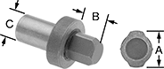 |
Round Head | Diamond Head |
The shoulder provides a consistent height reference point and keeps the pin from being pressed through the fixture. Install these pins in a plate or table and mate with holes in a workpiece for precise alignment. Press the shank into a drilled hole for permanent installation.
Diamond Head—Diamond-head pins make less contact with the inside of a hole than round-head pins to reduce sticking and jamming.
Head | Shoulder | Tolerance | Round Head | Diamond Head | |||||||||||||||||||||||||||||||||||||||||||||||||||||||||||||||||||||||||||||||||||||||||||||||
|---|---|---|---|---|---|---|---|---|---|---|---|---|---|---|---|---|---|---|---|---|---|---|---|---|---|---|---|---|---|---|---|---|---|---|---|---|---|---|---|---|---|---|---|---|---|---|---|---|---|---|---|---|---|---|---|---|---|---|---|---|---|---|---|---|---|---|---|---|---|---|---|---|---|---|---|---|---|---|---|---|---|---|---|---|---|---|---|---|---|---|---|---|---|---|---|---|---|---|---|
Dia. (A) | Ht. (B) | Shank Dia. (C) | Dia. | Ht. | Overall Ht. | Head Dia. | Shank Dia. | Hardness | Each | Each | |||||||||||||||||||||||||||||||||||||||||||||||||||||||||||||||||||||||||||||||||||||||||
Steel | |||||||||||||||||||||||||||||||||||||||||||||||||||||||||||||||||||||||||||||||||||||||||||||||||||
| 1/8" | 7/16" | 5/16" | 5/8" | 17/64" | 1 3/16" | -0.0005" to 0" | -0.0005" to 0" | Rockwell C48 to Rockwell C55 | ——— | 0 | 00000000 | 000000 | |||||||||||||||||||||||||||||||||||||||||||||||||||||||||||||||||||||||||||||||||||||||
| 1/8" | 7/16" | 5/16" | 5/8" | 17/64" | 1 3/16" | -0.0005" to 0" | -0.0005" to 0" | Rockwell C60 | 00000000 | 000000 | ——— | 0 | |||||||||||||||||||||||||||||||||||||||||||||||||||||||||||||||||||||||||||||||||||||||
| 3/16" | 7/16" | 5/16" | 5/8" | 17/64" | 1 3/16" | -0.0005" to 0" | -0.0005" to 0" | Rockwell C48 to Rockwell C55 | ——— | 0 | 00000000 | 00000 | |||||||||||||||||||||||||||||||||||||||||||||||||||||||||||||||||||||||||||||||||||||||
| 3/16" | 7/16" | 5/16" | 5/8" | 17/64" | 1 3/16" | -0.0005" to 0" | -0.0005" to 0" | Rockwell C60 | 00000000 | 00000 | ——— | 0 | |||||||||||||||||||||||||||||||||||||||||||||||||||||||||||||||||||||||||||||||||||||||
| 1/4" | 7/16" | 5/16" | 5/8" | 17/64" | 1 3/16" | -0.0005" to 0" | -0.0005" to 0" | Rockwell C48 to Rockwell C55 | ——— | 0 | 00000000 | 00000 | |||||||||||||||||||||||||||||||||||||||||||||||||||||||||||||||||||||||||||||||||||||||
| 1/4" | 7/16" | 5/16" | 5/8" | 17/64" | 1 3/16" | -0.0005" to 0" | -0.0005" to 0" | Rockwell C60 | 00000000 | 00000 | ——— | 0 | |||||||||||||||||||||||||||||||||||||||||||||||||||||||||||||||||||||||||||||||||||||||
| 5/16" | 7/16" | 5/16" | 5/8" | 17/64" | 1 3/16" | -0.0005" to 0" | -0.0005" to 0" | Rockwell C48 to Rockwell C55 | ——— | 0 | 00000000 | 00000 | |||||||||||||||||||||||||||||||||||||||||||||||||||||||||||||||||||||||||||||||||||||||
| 5/16" | 7/16" | 5/16" | 5/8" | 17/64" | 1 3/16" | -0.0005" to 0" | -0.0005" to 0" | Rockwell C60 | 00000000 | 00000 | ——— | 0 | |||||||||||||||||||||||||||||||||||||||||||||||||||||||||||||||||||||||||||||||||||||||
| 11/32" | 1/2" | 1/2" | 7/8" | 17/64" | 1 1/2" | -0.0005" to 0" | -0.0005" to 0" | Rockwell C48 to Rockwell C55 | ——— | 0 | 00000000 | 00000 | |||||||||||||||||||||||||||||||||||||||||||||||||||||||||||||||||||||||||||||||||||||||
| 11/32" | 1/2" | 1/2" | 7/8" | 17/64" | 1 1/2" | -0.0005" to 0" | -0.0005" to 0" | Rockwell C60 | 00000000 | 00000 | ——— | 0 | |||||||||||||||||||||||||||||||||||||||||||||||||||||||||||||||||||||||||||||||||||||||
| 3/8" | 1/2" | 1/2" | 7/8" | 17/64" | 1 1/2" | -0.0005" to 0" | -0.0005" to 0" | Rockwell C48 to Rockwell C55 | ——— | 0 | 00000000 | 00000 | |||||||||||||||||||||||||||||||||||||||||||||||||||||||||||||||||||||||||||||||||||||||
| 3/8" | 1/2" | 1/2" | 7/8" | 17/64" | 1 1/2" | -0.0005" to 0" | -0.0005" to 0" | Rockwell C60 | 00000000 | 00000 | ——— | 0 | |||||||||||||||||||||||||||||||||||||||||||||||||||||||||||||||||||||||||||||||||||||||
| 13/32" | 1/2" | 1/2" | 7/8" | 17/64" | 1 1/2" | -0.0005" to 0" | -0.0005" to 0" | Rockwell C48 to Rockwell C55 | ——— | 0 | 00000000 | 00000 | |||||||||||||||||||||||||||||||||||||||||||||||||||||||||||||||||||||||||||||||||||||||
| 13/32" | 1/2" | 1/2" | 7/8" | 17/64" | 1 1/2" | -0.0005" to 0" | -0.0005" to 0" | Rockwell C60 | 00000000 | 00000 | ——— | 0 | |||||||||||||||||||||||||||||||||||||||||||||||||||||||||||||||||||||||||||||||||||||||
| 7/16" | 1/2" | 1/2" | 7/8" | 17/64" | 1 1/2" | -0.0005" to 0" | -0.0005" to 0" | Rockwell C48 to Rockwell C55 | ——— | 0 | 00000000 | 00000 | |||||||||||||||||||||||||||||||||||||||||||||||||||||||||||||||||||||||||||||||||||||||
| 7/16" | 1/2" | 1/2" | 7/8" | 17/64" | 1 1/2" | -0.0005" to 0" | -0.0005" to 0" | Rockwell C60 | 00000000 | 00000 | ——— | 0 | |||||||||||||||||||||||||||||||||||||||||||||||||||||||||||||||||||||||||||||||||||||||
| 1/2" | 1/2" | 1/2" | 7/8" | 17/64" | 1 1/2" | -0.0005" to 0" | -0.0005" to 0" | Rockwell C48 to Rockwell C55 | ——— | 0 | 00000000 | 00000 | |||||||||||||||||||||||||||||||||||||||||||||||||||||||||||||||||||||||||||||||||||||||
| 1/2" | 1/2" | 1/2" | 7/8" | 17/64" | 1 1/2" | -0.0005" to 0" | -0.0005" to 0" | Rockwell C60 | 00000000 | 00000 | ——— | 0 | |||||||||||||||||||||||||||||||||||||||||||||||||||||||||||||||||||||||||||||||||||||||
| 9/16" | 11/16" | 3/4" | 1 1/8" | 17/64" | 1 15/16" | -0.0005" to 0" | -0.0005" to 0" | Rockwell C60 | 00000000 | 00000 | 00000000 | 00000 | |||||||||||||||||||||||||||||||||||||||||||||||||||||||||||||||||||||||||||||||||||||||
| 5/8" | 11/16" | 3/4" | 1 1/8" | 17/64" | 1 15/16" | -0.0005" to 0" | -0.0005" to 0" | Rockwell C60 | 00000000 | 00000 | 00000000 | 00000 | |||||||||||||||||||||||||||||||||||||||||||||||||||||||||||||||||||||||||||||||||||||||
| 3/4" | 11/16" | 3/4" | 1 1/8" | 17/64" | 1 15/16" | -0.0005" to 0" | -0.0005" to 0" | Rockwell C60 | 00000000 | 00000 | 00000000 | 00000 | |||||||||||||||||||||||||||||||||||||||||||||||||||||||||||||||||||||||||||||||||||||||
| 1" | 1" | 1" | 1 1/2" | 17/64" | 2 5/8" | -0.0005" to 0" | -0.0005" to 0" | Rockwell C48 to Rockwell C55 | 00000000 | 00000 | ——— | 0 | |||||||||||||||||||||||||||||||||||||||||||||||||||||||||||||||||||||||||||||||||||||||
| 1" | 1" | 1" | 1 1/2" | 17/64" | 2 5/8" | -0.0005" to 0" | -0.0005" to 0" | Rockwell C60 | ——— | 0 | 00000000 | 00000 | |||||||||||||||||||||||||||||||||||||||||||||||||||||||||||||||||||||||||||||||||||||||
Threaded Locating Pins
 | 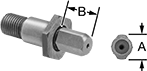 |
Round Head | Diamond Head |
Screw the shank into a threaded hole for quick installation and removal. Mate these pins with holes in workpieces for precise alignment.
Diamond Head—Diamond-head pins make less contact with the inside of a hole than round-head pins to reduce sticking and jamming.
Head | Thread | Round Head | Diamond Head | ||||||||||||||||||||||||||||||||||||||||||||||||||||||||||||||||||||||||||||||||||||||||||||||||
|---|---|---|---|---|---|---|---|---|---|---|---|---|---|---|---|---|---|---|---|---|---|---|---|---|---|---|---|---|---|---|---|---|---|---|---|---|---|---|---|---|---|---|---|---|---|---|---|---|---|---|---|---|---|---|---|---|---|---|---|---|---|---|---|---|---|---|---|---|---|---|---|---|---|---|---|---|---|---|---|---|---|---|---|---|---|---|---|---|---|---|---|---|---|---|---|---|---|---|---|
Dia. (A) | Ht. (B) | Size | Lg. | Shoulder Ht. | Overall Ht. | Head Dia. Tolerance | Hardness | Each | Each | ||||||||||||||||||||||||||||||||||||||||||||||||||||||||||||||||||||||||||||||||||||||||||
Steel | |||||||||||||||||||||||||||||||||||||||||||||||||||||||||||||||||||||||||||||||||||||||||||||||||||
| 1/8" | 7/16" | 1/4"-28 | 5/16" | 3/32" | 1 1/4" | -0.001" to -0.0005" | Rockwell C60 to Rockwell C64 | 0000000 | 000000 | 0000000 | 000000 | ||||||||||||||||||||||||||||||||||||||||||||||||||||||||||||||||||||||||||||||||||||||||
| 3/16" | 7/16" | 1/4"-28 | 5/16" | 3/32" | 1 1/4" | -0.001" to -0.0005" | Rockwell C60 to Rockwell C64 | 0000000 | 00000 | 0000000 | 00000 | ||||||||||||||||||||||||||||||||||||||||||||||||||||||||||||||||||||||||||||||||||||||||
| 1/4" | 7/16" | 1/4"-20 | 5/16" | 3/32" | 1 1/4" | -0.0015" to -0.001" | Rockwell C48 to Rockwell C55 | 0000000 | 00000 | 0000000 | 00000 | ||||||||||||||||||||||||||||||||||||||||||||||||||||||||||||||||||||||||||||||||||||||||
| 1/4" | 7/16" | 1/4"-28 | 5/16" | 3/32" | 1 1/4" | -0.0015" to -0.001" | Rockwell C60 to Rockwell C64 | 0000000 | 00000 | 0000000 | 00000 | ||||||||||||||||||||||||||||||||||||||||||||||||||||||||||||||||||||||||||||||||||||||||
| 5/16" | 7/16" | 1/4"-20 | 5/16" | 3/32" | 1 1/4" | -0.001" to -0.0005" | Rockwell C48 to Rockwell C55 | 0000000 | 00000 | 0000000 | 00000 | ||||||||||||||||||||||||||||||||||||||||||||||||||||||||||||||||||||||||||||||||||||||||
| 5/16" | 7/16" | 1/4"-28 | 5/16" | 3/32" | 1 1/4" | -0.001" to -0.0005" | Rockwell C60 to Rockwell C64 | 0000000 | 00000 | 0000000 | 00000 | ||||||||||||||||||||||||||||||||||||||||||||||||||||||||||||||||||||||||||||||||||||||||
| 3/8" | 1/2" | 3/8"-24 | 1/2" | 1/8" | 1 19/32" | -0.0015" to -0.001" | Rockwell C60 to Rockwell C64 | 0000000 | 00000 | 0000000 | 00000 | ||||||||||||||||||||||||||||||||||||||||||||||||||||||||||||||||||||||||||||||||||||||||
| 7/16" | 1/2" | 3/8"-24 | 1/2" | 1/8" | 1 19/32" | -0.0015" to -0.001" | Rockwell C60 to Rockwell C64 | 0000000 | 00000 | 0000000 | 00000 | ||||||||||||||||||||||||||||||||||||||||||||||||||||||||||||||||||||||||||||||||||||||||
| 1/2" | 11/16" | 1/2"-13 | 11/16" | 5/32" | 2 1/8" | -0.0015" to -0.001" | Rockwell C48 to Rockwell C55 | 0000000 | 00000 | 0000000 | 00000 | ||||||||||||||||||||||||||||||||||||||||||||||||||||||||||||||||||||||||||||||||||||||||
| 1/2" | 11/16" | 1/2"-20 | 11/16" | 5/32" | 2 1/8" | -0.0015" to -0.001" | Rockwell C60 to Rockwell C64 | 0000000 | 00000 | 0000000 | 00000 | ||||||||||||||||||||||||||||||||||||||||||||||||||||||||||||||||||||||||||||||||||||||||
| 9/16" | 11/16" | 1/2"-20 | 21/32" | 5/32" | 2 1/8" | -0.0015" to -0.001" | Rockwell C60 to Rockwell C64 | 0000000 | 00000 | 0000000 | 00000 | ||||||||||||||||||||||||||||||||||||||||||||||||||||||||||||||||||||||||||||||||||||||||
| 3/4" | 1" | 3/4"-16 | 23/32" | 1/4" | 2 31/32" | -0.0015" to -0.001" | Rockwell C60 to Rockwell C64 | 0000000 | 00000 | 0000000 | 00000 | ||||||||||||||||||||||||||||||||||||||||||||||||||||||||||||||||||||||||||||||||||||||||
| 1" | 1" | 3/4"-16 | 23/32" | 1/4" | 2 31/32" | -0.0015" to -0.001" | Rockwell C60 to Rockwell C64 | 0000000 | 00000 | 0000000 | 00000 | ||||||||||||||||||||||||||||||||||||||||||||||||||||||||||||||||||||||||||||||||||||||||
