


Filter by
Length
Performance
Electrical Connection
Export Control Classification Number (ECCN)
DFARS Specialty Metals


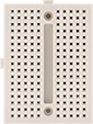
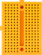
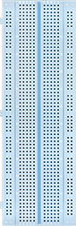
No-Solder Ready-to-Use Circuit Boards
Circuit Boards
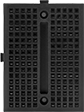 | 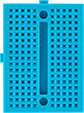 | 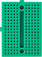 | 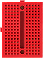 |
Black ABS | Blue ABS | Green ABS | Red ABS |
 |  |  | |
White ABS | Yellow ABS | Acetal |
Terminal Strips | Distribution Strips | ||||||||||||||||||||||||||||||||||||||||||||||||||||||||||||||||||||||||||||||||||||||||||||||||||
|---|---|---|---|---|---|---|---|---|---|---|---|---|---|---|---|---|---|---|---|---|---|---|---|---|---|---|---|---|---|---|---|---|---|---|---|---|---|---|---|---|---|---|---|---|---|---|---|---|---|---|---|---|---|---|---|---|---|---|---|---|---|---|---|---|---|---|---|---|---|---|---|---|---|---|---|---|---|---|---|---|---|---|---|---|---|---|---|---|---|---|---|---|---|---|---|---|---|---|---|
Total No. of Contact Points | No. of | No. of Contact Points | No. of | No. of Contact Points | Lg. | Wd. | Thk. | Hole Ctr.-to-Ctr. | Max. Temp., ° F | Choose a Color | Each | ||||||||||||||||||||||||||||||||||||||||||||||||||||||||||||||||||||||||||||||||||||||||
ABS | |||||||||||||||||||||||||||||||||||||||||||||||||||||||||||||||||||||||||||||||||||||||||||||||||||
| 170 | 2 | 85 | 0 | 0 | 1 7/8" | 1 7/16" | 5/16" | 0.1" | 155 | Black, Blue, Green, Red, White, Yellow | 8813N111 | 00000 | |||||||||||||||||||||||||||||||||||||||||||||||||||||||||||||||||||||||||||||||||||||||
Acetal | |||||||||||||||||||||||||||||||||||||||||||||||||||||||||||||||||||||||||||||||||||||||||||||||||||
| 400 | 1 | 300 | 2 | 50 | 3 5/16" | 2 1/8" | 5/16" | 0.1" | 300 | White | 8311N12 | 0000 | |||||||||||||||||||||||||||||||||||||||||||||||||||||||||||||||||||||||||||||||||||||||
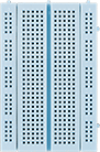
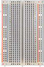
Circuit Boards with Numbered and Lettered Holes
 |  |
ABS | Acetal |
Terminal Strips | Distribution Strips | ||||||||||||||||||||||||||||||||||||||||||||||||||||||||||||||||||||||||||||||||||||||||||||||||||
|---|---|---|---|---|---|---|---|---|---|---|---|---|---|---|---|---|---|---|---|---|---|---|---|---|---|---|---|---|---|---|---|---|---|---|---|---|---|---|---|---|---|---|---|---|---|---|---|---|---|---|---|---|---|---|---|---|---|---|---|---|---|---|---|---|---|---|---|---|---|---|---|---|---|---|---|---|---|---|---|---|---|---|---|---|---|---|---|---|---|---|---|---|---|---|---|---|---|---|---|
Total No. of Contact Points | No. of | No. of Contact Points | No. of | No. of Contact Points | Lg. | Wd. | Thk. | Hole Ctr.-to-Ctr. | Color | Max. Temp., ° F | Includes | Each | |||||||||||||||||||||||||||||||||||||||||||||||||||||||||||||||||||||||||||||||||||||||
ABS | |||||||||||||||||||||||||||||||||||||||||||||||||||||||||||||||||||||||||||||||||||||||||||||||||||
| 400 | 1 | 300 | 2 | 50 | 3 5/16" | 2 1/8" | 5/16" | 0.1" | White | 180 | — | 1388N13 | 00000 | ||||||||||||||||||||||||||||||||||||||||||||||||||||||||||||||||||||||||||||||||||||||
| 830 | 1 | 630 | 2 | 100 | 2 1/8" | 6 1/2" | 5/16" | 0.1" | White | 180 | 70 Jumper Wires (22 Ga., 0.1" to 5" lg.) 3 Connection Posts 5 Antislip Feet | 1388N15 | 00000 | ||||||||||||||||||||||||||||||||||||||||||||||||||||||||||||||||||||||||||||||||||||||
| 830 | 1 | 630 | 2 | 100 | 6 1/2" | 2 1/8" | 5/16" | 0.1" | White | 180 | — | 1388N11 | 0000 | ||||||||||||||||||||||||||||||||||||||||||||||||||||||||||||||||||||||||||||||||||||||
| 830 | 1 | 630 | 2 | 100 | 6 1/2" | 2 1/8" | 5/16" | 0.1" | White | 180 | 70 Jumper Wires (22 Ga., 0.1" to 5" lg.) | 1388N14 | 00000 | ||||||||||||||||||||||||||||||||||||||||||||||||||||||||||||||||||||||||||||||||||||||
| 2,390 | 3 | 630 | 5 | 100 | 6 7/8" | 6 1/2" | 5/16" | 0.1" | White | 180 | 140 Jumper Wires (22 Ga., 0.1" to 5" lg.) 4 Connection Posts 5 Antislip Feet | 1388N12 | 00000 | ||||||||||||||||||||||||||||||||||||||||||||||||||||||||||||||||||||||||||||||||||||||
Acetal | |||||||||||||||||||||||||||||||||||||||||||||||||||||||||||||||||||||||||||||||||||||||||||||||||||
| 830 | 1 | 630 | 2 | 100 | 6 1/2" | 2 1/8" | 5/16" | 0.1" | White | 300 | — | 8311N11 | 00000 | ||||||||||||||||||||||||||||||||||||||||||||||||||||||||||||||||||||||||||||||||||||||
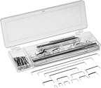
Ready-to-Use Circuit Board Kits
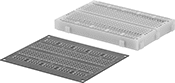 |
Rapidly prototype and troubleshoot issues on a no-solder circuit board and then transfer your final design to a board with solder pads for permanent connections. These kits come with two boards that have the same markings and layout, so it's easy to translate your prototype to your final design.
Terminal Strips | Distribution Strips | |||||||||||
|---|---|---|---|---|---|---|---|---|---|---|---|---|
Lg. | Wd. | Hole Ctr.-to-Ctr. | No. of Pieces | Includes | Total No. of Contact Points | No. of | No. of Contact Points | No. of | No. of Contact Points | Each | ||
| 3 5/16" | 2 11/16" | 0.1" | 2 | One Circuit Board with Through-Hole Solder Pad—Green Fiberglass-Reinforced Plastic One No-Solder Circuit Board—White ABS | 400 | 1 | 300 | 2 | 50 | 7622N12 | 000000 | |
| 6 5/8" | 2 3/4" | 0.1" | 2 | One Circuit Board with Through-Hole Solder Pad—Green Fiberglass-Reinforced Plastic One No-Solder Circuit Board—White ABS | 830 | 1 | 630 | 2 | 100 | 7622N11 | 00000 | |
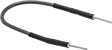
Circuit Board Cords
Lg. | Outer Jacket | ||||||||||||||||||||||||||||||||||||||||||||||||||||||||||||||||||||||||||||||||||||||||||||||||||
|---|---|---|---|---|---|---|---|---|---|---|---|---|---|---|---|---|---|---|---|---|---|---|---|---|---|---|---|---|---|---|---|---|---|---|---|---|---|---|---|---|---|---|---|---|---|---|---|---|---|---|---|---|---|---|---|---|---|---|---|---|---|---|---|---|---|---|---|---|---|---|---|---|---|---|---|---|---|---|---|---|---|---|---|---|---|---|---|---|---|---|---|---|---|---|---|---|---|---|---|
AWG | Wire Strand Count | Pin Dia./For Pin Dia. | Temp. Range, ° F | Inch | Metric, cm | Material | Color | Pkg. Qty. | Pkg. | ||||||||||||||||||||||||||||||||||||||||||||||||||||||||||||||||||||||||||||||||||||||||||
Stranded Wire | |||||||||||||||||||||||||||||||||||||||||||||||||||||||||||||||||||||||||||||||||||||||||||||||||||
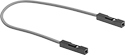 | |||||||||||||||||||||||||||||||||||||||||||||||||||||||||||||||||||||||||||||||||||||||||||||||||||
Female Machine-Pin Terminal × Female Machine-Pin Terminal | |||||||||||||||||||||||||||||||||||||||||||||||||||||||||||||||||||||||||||||||||||||||||||||||||||
| 24 | 11/34 | 0.025" × 0.025" | -40 to 175 | 1.97" | 5 | PVC | Black, Blue, Brown, Gray, Green, Orange, Purple, Red, White, Yellow | 10 | 3104N39 | 00000 | |||||||||||||||||||||||||||||||||||||||||||||||||||||||||||||||||||||||||||||||||||||||||
| 24 | 11/34 | 0.025" × 0.025" | -40 to 175 | 1.97" | 5 | PVC | Gray | 10 | 3104N14 | 0000 | |||||||||||||||||||||||||||||||||||||||||||||||||||||||||||||||||||||||||||||||||||||||||
| 24 | 11/34 | 0.025" × 0.025" | -40 to 175 | 3.94" | 10 | PVC | Black, Blue, Brown, Gray, Green, Orange, Purple, Red, White, Yellow | 10 | 3104N41 | 0000 | |||||||||||||||||||||||||||||||||||||||||||||||||||||||||||||||||||||||||||||||||||||||||
| 24 | 11/34 | 0.025" × 0.025" | -40 to 175 | 3.94" | 10 | PVC | White | 10 | 3104N15 | 0000 | |||||||||||||||||||||||||||||||||||||||||||||||||||||||||||||||||||||||||||||||||||||||||
| 24 | 11/34 | 0.025" × 0.025" | -40 to 175 | 7.87" | 20 | PVC | Black, Blue, Brown, Gray, Green, Orange, Purple, Red, White, Yellow | 10 | 3104N42 | 0000 | |||||||||||||||||||||||||||||||||||||||||||||||||||||||||||||||||||||||||||||||||||||||||
| 24 | 11/34 | 0.025" × 0.025" | -40 to 175 | 7.87" | 20 | PVC | Purple | 10 | 3104N16 | 00000 | |||||||||||||||||||||||||||||||||||||||||||||||||||||||||||||||||||||||||||||||||||||||||
| 24 | 11/34 | 0.025" × 0.025" | -40 to 175 | 11.81" | 30 | PVC | Black, Blue, Brown, Gray, Green, Orange, Purple, Red, White, Yellow | 10 | 3104N43 | 0000 | |||||||||||||||||||||||||||||||||||||||||||||||||||||||||||||||||||||||||||||||||||||||||
 | |||||||||||||||||||||||||||||||||||||||||||||||||||||||||||||||||||||||||||||||||||||||||||||||||||
Male Machine-Pin Terminal × Female Machine-Pin Terminal | |||||||||||||||||||||||||||||||||||||||||||||||||||||||||||||||||||||||||||||||||||||||||||||||||||
| 24 | 11/34 | 0.025" × 0.025" | -40 to 175 | 1.97" | 5 | PVC | Black, Blue, Brown, Gray, Green, Orange, Purple, Red, White, Yellow | 10 | 3104N35 | 0000 | |||||||||||||||||||||||||||||||||||||||||||||||||||||||||||||||||||||||||||||||||||||||||
| 24 | 11/34 | 0.025" × 0.025" | -40 to 175 | 1.97" | 5 | PVC | Yellow | 10 | 3104N17 | 0000 | |||||||||||||||||||||||||||||||||||||||||||||||||||||||||||||||||||||||||||||||||||||||||
| 24 | 11/34 | 0.025" × 0.025" | -40 to 175 | 3.94" | 10 | PVC | Black, Blue, Brown, Gray, Green, Orange, Purple, Red, White, Yellow | 10 | 3104N36 | 0000 | |||||||||||||||||||||||||||||||||||||||||||||||||||||||||||||||||||||||||||||||||||||||||
| 24 | 11/34 | 0.025" × 0.025" | -40 to 175 | 3.94" | 10 | PVC | Green | 10 | 3104N18 | 0000 | |||||||||||||||||||||||||||||||||||||||||||||||||||||||||||||||||||||||||||||||||||||||||
| 24 | 11/34 | 0.025" × 0.025" | -40 to 175 | 7.87" | 20 | PVC | Black | 10 | 3104N19 | 00000 | |||||||||||||||||||||||||||||||||||||||||||||||||||||||||||||||||||||||||||||||||||||||||
| 24 | 11/34 | 0.025" × 0.025" | -40 to 175 | 7.87" | 20 | PVC | Black, Blue, Brown, Gray, Green, Orange, Purple, Red, White, Yellow | 10 | 3104N37 | 0000 | |||||||||||||||||||||||||||||||||||||||||||||||||||||||||||||||||||||||||||||||||||||||||
| 24 | 11/34 | 0.025" × 0.025" | -40 to 175 | 11.81" | 30 | PVC | Black, Blue, Brown, Gray, Green, Orange, Purple, Red, White, Yellow | 10 | 3104N38 | 0000 | |||||||||||||||||||||||||||||||||||||||||||||||||||||||||||||||||||||||||||||||||||||||||
 | |||||||||||||||||||||||||||||||||||||||||||||||||||||||||||||||||||||||||||||||||||||||||||||||||||
Male Machine-Pin Terminal × Male Machine-Pin Terminal | |||||||||||||||||||||||||||||||||||||||||||||||||||||||||||||||||||||||||||||||||||||||||||||||||||
| 24 | 11/34 | 0.025" × 0.025" | -40 to 175 | 1.97" | 5 | PVC | Black, Blue, Brown, Gray, Green, Orange, Purple, Red, White, Yellow | 10 | 3104N31 | 0000 | |||||||||||||||||||||||||||||||||||||||||||||||||||||||||||||||||||||||||||||||||||||||||
| 24 | 11/34 | 0.025" × 0.025" | -40 to 175 | 1.97" | 5 | PVC | Brown | 10 | 3104N11 | 0000 | |||||||||||||||||||||||||||||||||||||||||||||||||||||||||||||||||||||||||||||||||||||||||
| 24 | 11/34 | 0.025" × 0.025" | -40 to 175 | 3.94" | 10 | PVC | Black, Blue, Brown, Gray, Green, Orange, Purple, Red, White, Yellow | 10 | 3104N32 | 0000 | |||||||||||||||||||||||||||||||||||||||||||||||||||||||||||||||||||||||||||||||||||||||||
| 24 | 11/34 | 0.025" × 0.025" | -40 to 175 | 3.94" | 10 | PVC | Orange | 10 | 3104N12 | 0000 | |||||||||||||||||||||||||||||||||||||||||||||||||||||||||||||||||||||||||||||||||||||||||
| 24 | 11/34 | 0.025" × 0.025" | -40 to 175 | 7.87" | 20 | PVC | Black, Blue, Brown, Gray, Green, Orange, Purple, Red, White, Yellow | 10 | 3104N33 | 0000 | |||||||||||||||||||||||||||||||||||||||||||||||||||||||||||||||||||||||||||||||||||||||||
| 24 | 11/34 | 0.025" × 0.025" | -40 to 175 | 7.87" | 20 | PVC | Blue | 10 | 3104N13 | 00000 | |||||||||||||||||||||||||||||||||||||||||||||||||||||||||||||||||||||||||||||||||||||||||
| 24 | 11/34 | 0.025" × 0.025" | -40 to 175 | 11.81" | 30 | PVC | Black, Blue, Brown, Gray, Green, Orange, Purple, Red, White, Yellow | 10 | 3104N34 | 0000 | |||||||||||||||||||||||||||||||||||||||||||||||||||||||||||||||||||||||||||||||||||||||||
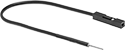
Circuit Board Cord Assortments
 | ||
6 Pieces, Female Machine-Pin Terminal × Alligator Clip | 6 Pieces, Male Machine-Pin Terminal × Alligator Clip | 140 Pieces |
Assortments include cords in multiple colors ready to connect to a circuit board.
6 Pieces—6-piece assortments include cords with a machine pin on one end and an alligator clip on the other end. Length does not include the machine pin or alligator clip.
140 Pieces—140-piece assortments include cords in multiple lengths. Length is measured along the insulated portion of the cord and does not include the 90° stripped ends.
Lg. | |||||||||||||||||||||||||||||||||||||||||||||||||||||||||||||||||||||||||||||||||||||||||||||||||||
|---|---|---|---|---|---|---|---|---|---|---|---|---|---|---|---|---|---|---|---|---|---|---|---|---|---|---|---|---|---|---|---|---|---|---|---|---|---|---|---|---|---|---|---|---|---|---|---|---|---|---|---|---|---|---|---|---|---|---|---|---|---|---|---|---|---|---|---|---|---|---|---|---|---|---|---|---|---|---|---|---|---|---|---|---|---|---|---|---|---|---|---|---|---|---|---|---|---|---|---|
AWG | Wire Strand Count | Total No. of Pieces | Electrical Connection | Pin Dia./For Pin Dia. | Temp. Range, ° F | Inch | Metric, cm | Outer Jacket Material | Includes | Features | Each | ||||||||||||||||||||||||||||||||||||||||||||||||||||||||||||||||||||||||||||||||||||||||
Stranded Wire—Push In | |||||||||||||||||||||||||||||||||||||||||||||||||||||||||||||||||||||||||||||||||||||||||||||||||||
| 24 | 11/34 | 6 | Female Machine-Pin Terminal × Alligator Clip | 0.025" | -40 to 175 | 8" | 20 | PVC | 1 of each Color: Black, Blue, Green, Red, White, Yellow | — | 3104N21 | 00000 | |||||||||||||||||||||||||||||||||||||||||||||||||||||||||||||||||||||||||||||||||||||||
| 24 | 11/34 | 6 | Male Machine-Pin Terminal × Alligator Clip | 0.025" | -40 to 175 | 8" | 20 | PVC | 1 of each Color: Black, Blue, Green, Red, White, Yellow | — | 3104N22 | 0000 | |||||||||||||||||||||||||||||||||||||||||||||||||||||||||||||||||||||||||||||||||||||||
Solid Wire—Push In/Solder | |||||||||||||||||||||||||||||||||||||||||||||||||||||||||||||||||||||||||||||||||||||||||||||||||||
| 22 | — | 140 | — | — | -40 to 175 | — | — | PVC | 10 of each Length: 0.1" (2.5 mm), 0.2" (5 mm), 0.3" (8 mm), 0.4" (10 mm) 0.5" (13 mm), 0.6" (15 mm), 0.7" (18 mm), 0.8" (20 mm) 0.9" (22 mm), 1" (25 mm), 2" (51 mm), 3" (76 mm), 4" (101 mm), 5" (126 mm) | 1/4" Stripped 90° Ends | 3104N1 | 0000 | |||||||||||||||||||||||||||||||||||||||||||||||||||||||||||||||||||||||||||||||||||||||
Circuit Board Headers
Sold Individually
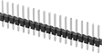 | 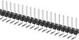 | 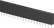 |
Male Header Straight Header | Male Header 90° Angle Header | Female Header Straight Header |
 |  |
Male Header | Female Header |
No. of | |||||||||||||||||||||||||||||||||||||||||||||||||||||||||||||||||||||||||||||||||||||||||||||||||||
|---|---|---|---|---|---|---|---|---|---|---|---|---|---|---|---|---|---|---|---|---|---|---|---|---|---|---|---|---|---|---|---|---|---|---|---|---|---|---|---|---|---|---|---|---|---|---|---|---|---|---|---|---|---|---|---|---|---|---|---|---|---|---|---|---|---|---|---|---|---|---|---|---|---|---|---|---|---|---|---|---|---|---|---|---|---|---|---|---|---|---|---|---|---|---|---|---|---|---|---|
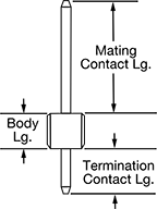
Total No. of Contact Points | Rows | Columns | For Hole Ctr.-to-Ctr. | Max. Current, amp | Mating Contact Lg. | Termination Contact Lg. | Body Lg. | Construction | Temp. Range, ° F | Each | |||||||||||||||||||||||||||||||||||||||||||||||||||||||||||||||||||||||||||||||||||||||||
Male Header | |||||||||||||||||||||||||||||||||||||||||||||||||||||||||||||||||||||||||||||||||||||||||||||||||||
Straight Header | |||||||||||||||||||||||||||||||||||||||||||||||||||||||||||||||||||||||||||||||||||||||||||||||||||
| 6 | 2 | 3 | 0.1" | 3 | 1/4" | 3/32" | 1/8" | Breakaway | -40 to 221 | 4002N17 | 00000 | ||||||||||||||||||||||||||||||||||||||||||||||||||||||||||||||||||||||||||||||||||||||||
| 10 | 1 | 10 | 2 mm | 1.5 | 5/32" | 3/32" | 3/32" | Breakaway | -40 to 221 | 4002N201 | 0000 | ||||||||||||||||||||||||||||||||||||||||||||||||||||||||||||||||||||||||||||||||||||||||
| 10 | 2 | 5 | 0.05" | 1 | 1/8" | 3/32" | 1/8" | Breakaway | -40 to 221 | 4002N208 | 0000 | ||||||||||||||||||||||||||||||||||||||||||||||||||||||||||||||||||||||||||||||||||||||||
| 40 | 1 | 40 | 0.1" | 3 | 1/4" | 1/8" | 1/8" | Breakaway | -40 to 221 | 4002N14 | 0000 | ||||||||||||||||||||||||||||||||||||||||||||||||||||||||||||||||||||||||||||||||||||||||
| 40 | 1 | 40 | 0.1" | 3 | 5/16" | 5/16" | 3/32" | Breakaway | -40 to 221 | 4002N204 | 0000 | ||||||||||||||||||||||||||||||||||||||||||||||||||||||||||||||||||||||||||||||||||||||||
| 40 | 1 | 40 | 0.1" | 3 | 9/16" | 1/8" | 1/8" | Breakaway | -40 to 221 | 4002N15 | 0000 | ||||||||||||||||||||||||||||||||||||||||||||||||||||||||||||||||||||||||||||||||||||||||
| 46 | 2 | 23 | 0.1" | 3 | 1/4" | 3/32" | 3/32" | Breakaway | -40 to 221 | 4002N205 | 0000 | ||||||||||||||||||||||||||||||||||||||||||||||||||||||||||||||||||||||||||||||||||||||||
90° Angle Header | |||||||||||||||||||||||||||||||||||||||||||||||||||||||||||||||||||||||||||||||||||||||||||||||||||
| 40 | 1 | 40 | 0.1" | 3 | 1/4" | 1/8" | 1/8" | Breakaway | -40 to 221 | 4002N16 | 0000 | ||||||||||||||||||||||||||||||||||||||||||||||||||||||||||||||||||||||||||||||||||||||||
| 80 | 2 | 40 | 0.1" | 3 | 1/4" | 1/8" | 3/32" | Breakaway | -40 to 221 | 4002N206 | 0000 | ||||||||||||||||||||||||||||||||||||||||||||||||||||||||||||||||||||||||||||||||||||||||
| 120 | 3 | 40 | 0.1" | 3 | 1/4" | 1/8" | 3/32" | Breakaway | -40 to 221 | 4002N214 | 0000 | ||||||||||||||||||||||||||||||||||||||||||||||||||||||||||||||||||||||||||||||||||||||||
Female Header | |||||||||||||||||||||||||||||||||||||||||||||||||||||||||||||||||||||||||||||||||||||||||||||||||||
Straight Header | |||||||||||||||||||||||||||||||||||||||||||||||||||||||||||||||||||||||||||||||||||||||||||||||||||
| 8 | 1 | 8 | 0.1" | 3 | — | 13/32" | 11/32" | Solid | -40 to 221 | 4002N203 | 0000 | ||||||||||||||||||||||||||||||||||||||||||||||||||||||||||||||||||||||||||||||||||||||||
| 10 | 1 | 10 | 2 mm | 1.5 | — | 3/32" | 5/32" | Solid | -40 to 221 | 4002N202 | 0000 | ||||||||||||||||||||||||||||||||||||||||||||||||||||||||||||||||||||||||||||||||||||||||
| 10 | 2 | 5 | 0.05" | 1 | — | 3/32" | 5/32" | Solid | -40 to 221 | 4002N209 | 0000 | ||||||||||||||||||||||||||||||||||||||||||||||||||||||||||||||||||||||||||||||||||||||||
| 12 | 2 | 6 | 0.1" | 3 | — | 1/8" | 11/32" | Solid | -40 to 221 | 4002N207 | 0000 | ||||||||||||||||||||||||||||||||||||||||||||||||||||||||||||||||||||||||||||||||||||||||
| 40 | 1 | 40 | 0.1" | 3 | — | 1/8" | 11/32" | Solid | -40 to 221 | 4002N13 | 0000 | ||||||||||||||||||||||||||||||||||||||||||||||||||||||||||||||||||||||||||||||||||||||||
| 40 | 2 | 20 | 0.1" | 3 | — | 1/8" | 17/32" | Solid | -40 to 221 | 4002N211 | 0000 | ||||||||||||||||||||||||||||||||||||||||||||||||||||||||||||||||||||||||||||||||||||||||
| 40 | 2 | 20 | 0.1" | 3 | — | 9/32" | 5/8" | Solid | -40 to 221 | 4002N213 | 0000 | ||||||||||||||||||||||||||||||||||||||||||||||||||||||||||||||||||||||||||||||||||||||||
| 40 | 2 | 20 | 0.1" | 3 | — | 3/8" | 17/32" | Solid | -40 to 221 | 4002N212 | 0000 | ||||||||||||||||||||||||||||||||||||||||||||||||||||||||||||||||||||||||||||||||||||||||
Sold as Sets
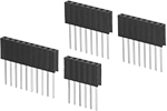 | |
Female Header Straight Header | Female Header |
Stack multiple boards by connecting the headers in these sets.
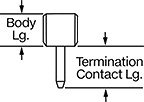
Includes | No. of Pieces | For Hole Ctr.-to-Ctr. | Max. Current, amp | Termination Contact Lg. | Body Lg. | Construction | Temp. Range, ° F | Each | |||||||||||||||||||||||||||||||||||||||||||||||||||||||||||||||||||||||||||||||||||||||||||
|---|---|---|---|---|---|---|---|---|---|---|---|---|---|---|---|---|---|---|---|---|---|---|---|---|---|---|---|---|---|---|---|---|---|---|---|---|---|---|---|---|---|---|---|---|---|---|---|---|---|---|---|---|---|---|---|---|---|---|---|---|---|---|---|---|---|---|---|---|---|---|---|---|---|---|---|---|---|---|---|---|---|---|---|---|---|---|---|---|---|---|---|---|---|---|---|---|---|---|---|
Female Header | |||||||||||||||||||||||||||||||||||||||||||||||||||||||||||||||||||||||||||||||||||||||||||||||||||
Straight Header—for Arduino Leonardo, Uno Series | |||||||||||||||||||||||||||||||||||||||||||||||||||||||||||||||||||||||||||||||||||||||||||||||||||
| One Header with 6 Contacts (1 Row × 6 Columns)—5/8" Body Width, Two Headers with 8 Contacts (1 Row × 8 Columns)—13/16" Body Width, One Header with 10 Contacts (1 Row × 10 Columns)—1" Body Width | 4 | 0.1" | 3 | 13/32" | 11/32" | Solid | -40 to 221 | 4002N11 | 00000 | ||||||||||||||||||||||||||||||||||||||||||||||||||||||||||||||||||||||||||||||||||||||||||
Straight Header—for Arduino Nano Series | |||||||||||||||||||||||||||||||||||||||||||||||||||||||||||||||||||||||||||||||||||||||||||||||||||
| Two Headers with 15 Contacts (1 Row × 15 Columns)—1 1/2" Body Width | 2 | 0.1" | 3 | 13/32" | 11/32" | Solid | -40 to 221 | 4002N12 | 0000 | ||||||||||||||||||||||||||||||||||||||||||||||||||||||||||||||||||||||||||||||||||||||||||
Build-Your-Own Molex Circuit Board Connectors
Sleeve Housings
Mated Housing | |||||||||||||||||||||||||||||||||||||||||||||||||||||||||||||||||||||||||||||||||||||||||||||||||||
|---|---|---|---|---|---|---|---|---|---|---|---|---|---|---|---|---|---|---|---|---|---|---|---|---|---|---|---|---|---|---|---|---|---|---|---|---|---|---|---|---|---|---|---|---|---|---|---|---|---|---|---|---|---|---|---|---|---|---|---|---|---|---|---|---|---|---|---|---|---|---|---|---|---|---|---|---|---|---|---|---|---|---|---|---|---|---|---|---|---|---|---|---|---|---|---|---|---|---|---|
For No. of Poles | For Hole Ctr.-to-Ctr. | For Max. Wire Ga. | Max. Voltage, V AC | Color | Housing Material | Ht. | Wd. | Dp. | Temp. Range, ° F | Pkg. Qty. | Pkg. | ||||||||||||||||||||||||||||||||||||||||||||||||||||||||||||||||||||||||||||||||||||||||
Molex KK 254 Connection | |||||||||||||||||||||||||||||||||||||||||||||||||||||||||||||||||||||||||||||||||||||||||||||||||||
| 2 | 0.1" | 22 | 500 | White | Nylon | 0.62" | 0.2" | 0.19" | -40 to 175 | 50 | 8193N25 | 00000 | |||||||||||||||||||||||||||||||||||||||||||||||||||||||||||||||||||||||||||||||||||||||
| 3 | 0.1" | 22 | 500 | White | Nylon | 0.62" | 0.3" | 0.19" | -40 to 175 | 50 | 8193N26 | 0000 | |||||||||||||||||||||||||||||||||||||||||||||||||||||||||||||||||||||||||||||||||||||||
| 4 | 0.1" | 22 | 500 | White | Nylon | 0.62" | 0.4" | 0.19" | -40 to 175 | 50 | 8193N27 | 0000 | |||||||||||||||||||||||||||||||||||||||||||||||||||||||||||||||||||||||||||||||||||||||
| 5 | 0.1" | 22 | 500 | White | Nylon | 0.62" | 0.5" | 0.19" | -40 to 175 | 50 | 8193N28 | 0000 | |||||||||||||||||||||||||||||||||||||||||||||||||||||||||||||||||||||||||||||||||||||||
| 6 | 0.1" | 22 | 500 | White | Nylon | 0.62" | 0.6" | 0.19" | -40 to 175 | 25 | 8193N29 | 0000 | |||||||||||||||||||||||||||||||||||||||||||||||||||||||||||||||||||||||||||||||||||||||
| 7 | 0.1" | 22 | 500 | White | Nylon | 0.62" | 0.7" | 0.19" | -40 to 175 | 25 | 8193N31 | 0000 | |||||||||||||||||||||||||||||||||||||||||||||||||||||||||||||||||||||||||||||||||||||||
| 8 | 0.1" | 22 | 500 | White | Nylon | 0.62" | 0.8" | 0.19" | -40 to 175 | 25 | 8193N32 | 0000 | |||||||||||||||||||||||||||||||||||||||||||||||||||||||||||||||||||||||||||||||||||||||
| 9 | 0.1" | 22 | 500 | White | Nylon | 0.62" | 0.9" | 0.19" | -40 to 175 | 25 | 8193N33 | 0000 | |||||||||||||||||||||||||||||||||||||||||||||||||||||||||||||||||||||||||||||||||||||||
| 10 | 0.1" | 22 | 500 | White | Nylon | 0.62" | 1" | 0.19" | -40 to 175 | 25 | 8193N34 | 0000 | |||||||||||||||||||||||||||||||||||||||||||||||||||||||||||||||||||||||||||||||||||||||
| 12 | 0.1" | 22 | 500 | White | Nylon | 0.62" | 1.2" | 0.19" | -40 to 175 | 15 | 8193N35 | 0000 | |||||||||||||||||||||||||||||||||||||||||||||||||||||||||||||||||||||||||||||||||||||||
| 14 | 0.1" | 22 | 500 | White | Nylon | 0.62" | 1.4" | 0.19" | -40 to 175 | 15 | 8193N36 | 0000 | |||||||||||||||||||||||||||||||||||||||||||||||||||||||||||||||||||||||||||||||||||||||
| 16 | 0.1" | 22 | 500 | White | Nylon | 0.62" | 1.6" | 0.19" | -40 to 175 | 15 | 8193N37 | 00000 | |||||||||||||||||||||||||||||||||||||||||||||||||||||||||||||||||||||||||||||||||||||||

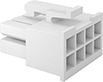
Circuit Board Plugs
Plugs have a friction clip to securely hold the housing when mated. They also have an alignment key that ensures the plug and housing are mated correctly, which is helpful when you can’t get a good look during installation. To install the plug on your circuit board, push the contacts through the board’s holes and solder them in place. The pins are gold-plated brass, so they resist corrosion better than tin- or nickel-plated pins. This means they’ll have a good, long-lasting electrical connection.
Mated Housing | |||||||||||||||||||||||||||||||||||||||||||||||||||||||||||||||||||||||||||||||||||||||||||||||||||
|---|---|---|---|---|---|---|---|---|---|---|---|---|---|---|---|---|---|---|---|---|---|---|---|---|---|---|---|---|---|---|---|---|---|---|---|---|---|---|---|---|---|---|---|---|---|---|---|---|---|---|---|---|---|---|---|---|---|---|---|---|---|---|---|---|---|---|---|---|---|---|---|---|---|---|---|---|---|---|---|---|---|---|---|---|---|---|---|---|---|---|---|---|---|---|---|---|---|---|---|
No. of Poles | For Hole Ctr.-to-Ctr. | Voltage, V AC | Current, amp | Color | Housing Material | Ht. | Wd. | Dp. | Pin Material | Temp. Range, ° F | Pkg. Qty. | Pkg. | |||||||||||||||||||||||||||||||||||||||||||||||||||||||||||||||||||||||||||||||||||||||
Molex KK 254 Connection | |||||||||||||||||||||||||||||||||||||||||||||||||||||||||||||||||||||||||||||||||||||||||||||||||||
| 2 | 0.1" | 500 | 4 | White | Nylon | 0.62" | 0.2" | 0.19" | Gold-Plated Brass | -40 to 175 | 20 | 8193N12 | 000000 | ||||||||||||||||||||||||||||||||||||||||||||||||||||||||||||||||||||||||||||||||||||||
| 3 | 0.1" | 500 | 4 | White | Nylon | 0.62" | 0.3" | 0.19" | Gold-Plated Brass | -40 to 175 | 20 | 8193N13 | 00000 | ||||||||||||||||||||||||||||||||||||||||||||||||||||||||||||||||||||||||||||||||||||||
| 4 | 0.1" | 500 | 4 | White | Nylon | 0.62" | 0.4" | 0.19" | Gold-Plated Brass | -40 to 175 | 10 | 8193N14 | 0000 | ||||||||||||||||||||||||||||||||||||||||||||||||||||||||||||||||||||||||||||||||||||||
| 5 | 0.1" | 500 | 4 | White | Nylon | 0.62" | 0.5" | 0.19" | Gold-Plated Brass | -40 to 175 | 10 | 8193N15 | 00000 | ||||||||||||||||||||||||||||||||||||||||||||||||||||||||||||||||||||||||||||||||||||||
| 6 | 0.1" | 500 | 4 | White | Nylon | 0.62" | 0.6" | 0.19" | Gold-Plated Brass | -40 to 175 | 10 | 8193N16 | 00000 | ||||||||||||||||||||||||||||||||||||||||||||||||||||||||||||||||||||||||||||||||||||||
| 7 | 0.1" | 500 | 4 | White | Nylon | 0.62" | 0.7" | 0.19" | Gold-Plated Brass | -40 to 175 | 5 | 8193N17 | 0000 | ||||||||||||||||||||||||||||||||||||||||||||||||||||||||||||||||||||||||||||||||||||||
| 8 | 0.1" | 500 | 4 | White | Nylon | 0.62" | 0.8" | 0.19" | Gold-Plated Brass | -40 to 175 | 5 | 8193N18 | 0000 | ||||||||||||||||||||||||||||||||||||||||||||||||||||||||||||||||||||||||||||||||||||||
| 9 | 0.1" | 500 | 4 | White | Nylon | 0.62" | 0.9" | 0.19" | Gold-Plated Brass | -40 to 175 | 5 | 8193N19 | 00000 | ||||||||||||||||||||||||||||||||||||||||||||||||||||||||||||||||||||||||||||||||||||||
| 10 | 0.1" | 500 | 4 | White | Nylon | 0.62" | 1" | 0.19" | Gold-Plated Brass | -40 to 175 | 5 | 8193N21 | 00000 | ||||||||||||||||||||||||||||||||||||||||||||||||||||||||||||||||||||||||||||||||||||||
| 12 | 0.1" | 500 | 4 | White | Nylon | 0.62" | 1.2" | 0.19" | Gold-Plated Brass | -40 to 175 | 5 | 8193N22 | 00000 | ||||||||||||||||||||||||||||||||||||||||||||||||||||||||||||||||||||||||||||||||||||||
| 14 | 0.1" | 500 | 4 | White | Nylon | 0.62" | 1.4" | 0.19" | Gold-Plated Brass | -40 to 175 | 5 | 8193N23 | 00000 | ||||||||||||||||||||||||||||||||||||||||||||||||||||||||||||||||||||||||||||||||||||||
| 16 | 0.1" | 500 | 4 | White | Nylon | 0.62" | 1.6" | 0.19" | Gold-Plated Brass | -40 to 175 | 5 | 8193N24 | 00000 | ||||||||||||||||||||||||||||||||||||||||||||||||||||||||||||||||||||||||||||||||||||||
Build-Your-Own Molex Circuit Board Connectors with Locking Tab
Sleeve Housings
 |
Mated Housing | |||||||||||||||||||||||||||||||||||||||||||||||||||||||||||||||||||||||||||||||||||||||||||||||||||
|---|---|---|---|---|---|---|---|---|---|---|---|---|---|---|---|---|---|---|---|---|---|---|---|---|---|---|---|---|---|---|---|---|---|---|---|---|---|---|---|---|---|---|---|---|---|---|---|---|---|---|---|---|---|---|---|---|---|---|---|---|---|---|---|---|---|---|---|---|---|---|---|---|---|---|---|---|---|---|---|---|---|---|---|---|---|---|---|---|---|---|---|---|---|---|---|---|---|---|---|
For No. of Poles | For Hole Ctr.-to-Ctr. | For Max. Wire Ga. | Max. Voltage, V AC | Color | Housing Material | Ht. | Wd. | Dp. | Temp. Range, ° F | Pkg. Qty. | Pkg. | ||||||||||||||||||||||||||||||||||||||||||||||||||||||||||||||||||||||||||||||||||||||||
Molex Mini-Fit Jr. Connection | |||||||||||||||||||||||||||||||||||||||||||||||||||||||||||||||||||||||||||||||||||||||||||||||||||
| 2 | 0.1" | 18 | 600 | White | Nylon | 0.93" | 0.29" | 0.57" | -40 to 220 | 25 | 7474N13 | 000000 | |||||||||||||||||||||||||||||||||||||||||||||||||||||||||||||||||||||||||||||||||||||||
| 4 | 0.1" | 18 | 600 | White | Nylon | 0.93" | 0.46" | 0.57" | -40 to 220 | 25 | 7474N14 | 00000 | |||||||||||||||||||||||||||||||||||||||||||||||||||||||||||||||||||||||||||||||||||||||
| 6 | 0.1" | 18 | 600 | White | Nylon | 0.93" | 0.54" | 0.57" | -40 to 220 | 25 | 7474N15 | 00000 | |||||||||||||||||||||||||||||||||||||||||||||||||||||||||||||||||||||||||||||||||||||||
| 8 | 0.1" | 18 | 600 | White | Nylon | 0.93" | 0.71" | 0.57" | -40 to 220 | 25 | 7474N16 | 00000 | |||||||||||||||||||||||||||||||||||||||||||||||||||||||||||||||||||||||||||||||||||||||
| 10 | 0.1" | 18 | 600 | White | Nylon | 0.93" | 0.87" | 0.57" | -40 to 220 | 25 | 7474N17 | 00000 | |||||||||||||||||||||||||||||||||||||||||||||||||||||||||||||||||||||||||||||||||||||||
| 12 | 0.1" | 18 | 600 | White | Nylon | 0.93" | 1.04" | 0.57" | -40 to 220 | 25 | 7474N18 | 00000 | |||||||||||||||||||||||||||||||||||||||||||||||||||||||||||||||||||||||||||||||||||||||
| 14 | 0.1" | 18 | 600 | White | Nylon | 0.93" | 1.2" | 0.57" | -40 to 220 | 25 | 7474N19 | 00000 | |||||||||||||||||||||||||||||||||||||||||||||||||||||||||||||||||||||||||||||||||||||||
| 16 | 0.1" | 18 | 600 | White | Nylon | 0.93" | 1.37" | 0.57" | -40 to 220 | 25 | 7474N21 | 00000 | |||||||||||||||||||||||||||||||||||||||||||||||||||||||||||||||||||||||||||||||||||||||
For Wire Ga. | Material | Each | ||
|---|---|---|---|---|
| 30, 28, 26, 24, 22, 20, 18, 16, 14 | Metal | 7474N11 | 000000 |

Circuit Board Plugs
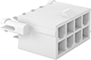 |
Plugs have an alignment key that ensures the plug and housing are mated correctly, which is helpful when you can’t get a good look during installation. A locking tab holds the housing and plug together once they’re mated. To install the plug on your circuit board, push the contacts through the board’s holes and solder them in place. All plugs have gold-plated brass pins, which are more corrosion resistant than tin- or nickel-plated pins, so the electrical connection lasts longer.
Snap-In Pegs—Plugs with snap-in pegs relieve stress on the terminal when plugging and unplugging wires.
Mated Housing | |||||||||||||||||||||||||||||||||||||||||||||||||||||||||||||||||||||||||||||||||||||||||||||||||||
|---|---|---|---|---|---|---|---|---|---|---|---|---|---|---|---|---|---|---|---|---|---|---|---|---|---|---|---|---|---|---|---|---|---|---|---|---|---|---|---|---|---|---|---|---|---|---|---|---|---|---|---|---|---|---|---|---|---|---|---|---|---|---|---|---|---|---|---|---|---|---|---|---|---|---|---|---|---|---|---|---|---|---|---|---|---|---|---|---|---|---|---|---|---|---|---|---|---|---|---|
No. of Poles | For Hole Ctr.-to-Ctr. | Voltage, V AC | Current, amp | Color | Housing Material | Ht. | Wd. | Dp. | Pin Material | Temp. Range, ° F | Features | Pkg. Qty. | Pkg. | ||||||||||||||||||||||||||||||||||||||||||||||||||||||||||||||||||||||||||||||||||||||
Molex Mini-Fit Jr. Connection | |||||||||||||||||||||||||||||||||||||||||||||||||||||||||||||||||||||||||||||||||||||||||||||||||||
| 2 | 0.1" | 600 | 9 | White | Nylon | 0.93" | 0.29" | 0.57" | Gold-Plated Brass | -40 to 220 | Locking Tab | 10 | 7474N22 | 000000 | |||||||||||||||||||||||||||||||||||||||||||||||||||||||||||||||||||||||||||||||||||||
| 4 | 0.1" | 600 | 9 | White | Nylon | 0.93" | 0.46" | 0.57" | Gold-Plated Brass | -40 to 220 | Locking Tab | 5 | 7474N23 | 00000 | |||||||||||||||||||||||||||||||||||||||||||||||||||||||||||||||||||||||||||||||||||||
| 6 | 0.1" | 600 | 9 | White | Nylon | 0.93" | 0.54" | 0.57" | Gold-Plated Brass | -40 to 220 | Locking Tab | 5 | 7474N24 | 00000 | |||||||||||||||||||||||||||||||||||||||||||||||||||||||||||||||||||||||||||||||||||||
| 8 | 0.1" | 600 | 9 | White | Nylon | 0.93" | 0.71" | 0.57" | Gold-Plated Brass | -40 to 220 | Locking Tab, Snap-In Pegs | 5 | 7474N25 | 00000 | |||||||||||||||||||||||||||||||||||||||||||||||||||||||||||||||||||||||||||||||||||||
| 10 | 0.1" | 600 | 9 | White | Nylon | 0.93" | 0.87" | 0.57" | Gold-Plated Brass | -40 to 220 | Locking Tab, Snap-In Pegs | 1 | 7474N26 | 0000 | |||||||||||||||||||||||||||||||||||||||||||||||||||||||||||||||||||||||||||||||||||||
| 12 | 0.1" | 600 | 9 | White | Nylon | 0.93" | 1.04" | 0.57" | Gold-Plated Brass | -40 to 220 | Locking Tab, Snap-In Pegs | 1 | 7474N27 | 0000 | |||||||||||||||||||||||||||||||||||||||||||||||||||||||||||||||||||||||||||||||||||||
| 14 | 0.1" | 600 | 9 | White | Nylon | 0.93" | 1.2" | 0.57" | Gold-Plated Brass | -40 to 220 | Locking Tab, Snap-In Pegs | 1 | 7474N28 | 0000 | |||||||||||||||||||||||||||||||||||||||||||||||||||||||||||||||||||||||||||||||||||||
| 16 | 0.1" | 600 | 9 | White | Nylon | 0.93" | 1.37" | 0.57" | Gold-Plated Brass | -40 to 220 | Locking Tab, Snap-In Pegs | 1 | 7474N29 | 00000 | |||||||||||||||||||||||||||||||||||||||||||||||||||||||||||||||||||||||||||||||||||||
Circuit Board Terminals
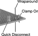 |
Terminals Installed on Circuit Board |
Terminals fit into 0.042" dia. holes so you can make connections to a circuit board.
Quick-Disconnect Terminals
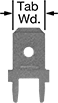 |
Quick-disconnect terminals provide fast, secure connections. The male tab fits into a female quick-disconnect terminal—pull them apart with ease. The solder tails attach to your circuit board. Terminals with a built-in tab support prevent side-to-side motion during termination.
Tab | ||||||||||||
|---|---|---|---|---|---|---|---|---|---|---|---|---|
Wd. | Thk. | Overall Ht. | Shape | Gender | Insulation | Terminal Material | Features | Certification | Pkg. Qty. | Pkg. | ||
| 0.187" | 0.02" | 0.51" | Straight | Male | Noninsulated | Tin-Plated Brass | — | UL Recognized Component | 100 | 7956K1 | 000000 | |
| 0.187" | 0.032" | 0.71" | Straight | Male | Noninsulated | Tin-Plated Brass | Built-In Tab Support | UL Recognized Component | 100 | 7956K3 | 00000 | |
| 1/4" | 0.032" | 0.56" | Straight | Male | Noninsulated | Tin-Plated Brass | — | UL Recognized Component | 100 | 7956K2 | 00000 | |
| 1/4" | 0.032" | 0.56" | Straight | Male | Noninsulated | Tin-Plated Brass | Built-In Tab Support | UL Recognized Component | 100 | 7956K4 | 00000 | |
| 1/4" | 0.032" | 0.71" | Straight | Male | Noninsulated | Tin-Plated Brass | Built-In Tab Support | UL Recognized Component | 100 | 7956K5 | 00000 | |
Clamp-On Post Terminals
Push clamp-on post terminals into the hole so that the clamp sits flush on top of the board. Solder your wire into the clamp.
