


Filter by
Diameter
Length
For Motion
OD
Ball Material
Overall Length
Spline Bearing Type
Bearing Material
DFARS Specialty Metals
Export Control Classification Number (ECCN)
Mounted Linear Bearings for Ball Splines
 |
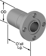
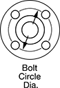
A flange with mounting holes makes it easy to attach a load to these bearings. Create a compact linear and rotary motion system for robots and other applications requiring complex, fast movements, by combining them with ball splines. These bearings move smoothly and precisely even at high speeds along ball splines while grooves on the ball spline transmit rotary power. Clip a retaining ring (not included) into the groove on these bearings to position them in your system.
Steel Bearings
 |  |  |
For 4 Splines |
Groove, mm | ||||||||||||||||||
|---|---|---|---|---|---|---|---|---|---|---|---|---|---|---|---|---|---|---|
For Spline Dia., mm | For No. of Splines | Overall Lg., mm | Flange OD, mm | Bolt Circle Dia., mm | OD, mm | Dynamic Load Cap., lb. | Static Load Cap., lb. | Max. Dynamic Torque, in·lbf | Max. Static Torque, in·lbf | Max. Temp., ° F | With Retaining Ring Grooves | Wd. | Dia. | No. of Mounting Holes | Each | |||
| 6 | 4 | 25 | 30 | 22 | 14 | 270 | 510 | 13 | 21 | 176 | Yes | 1.25 | 13.7 | 4 | 61145K41 | 0000000 | ||
| 8 | 4 | 25 | 32 | 24 | 16 | 325 | 645 | 18 | 32 | 176 | Yes | 1.25 | 15.6 | 4 | 61145K42 | 000000 | ||
| 10 | 4 | 33 | 42 | 32 | 21 | 610 | 1,100 | 38 | 72 | 176 | Yes | 1.65 | 20.5 | 4 | 61145K43 | 000000 | ||
| 13 | 4 | 36 | 43 | 33 | 24 | 600 | 1,050 | 185 | 346 | 176 | Yes | 1.3 | 22.7 | 4 | 61145K111 | 00000 | ||
| 16 | 4 | 50 | 50 | 40 | 31 | 1,350 | 2,500 | 531 | 973 | 176 | Yes | 1.6 | 29.4 | 4 | 61145K112 | 000000 | ||
| 18.2 | 4 | 60 | 51 | 40 | 32 | 1,750 | 2,500 | 734 | 1,177 | 176 | Yes | 3 | 31.3 | 4 | 61145K46 | 000000 | ||
| 20 | 4 | 63 | 58 | 45 | 35 | 2,000 | 3,650 | 929 | 1,717 | 176 | Yes | 2 | 33 | 4 | 61145K113 | 000000 | ||
| 23 | 4 | 70 | 60 | 47 | 37 | 2,750 | 3,600 | 1,433 | 2,115 | 176 | Yes | 3.5 | 36.1 | 4 | 61145K47 | 000000 | ||
| 25 | 4 | 71 | 65 | 52 | 42 | 2,850 | 5,250 | 1,672 | 3,062 | 176 | Yes | 2.5 | 39.5 | 4 | 61145K114 | 000000 | ||
| 28 | 4 | 80 | 70 | 54 | 45 | 4,150 | 5,200 | 2,557 | 3,646 | 176 | Yes | 4 | 43.9 | 4 | 61145K48 | 000000 | ||
| 30 | 4 | 80 | 75 | 60 | 47 | 4,150 | 5,200 | 2,716 | 3,885 | 176 | Yes | 3 | 44 | 4 | 61145K115 | 000000 | ||
| 37.4 | 4 | 100 | 90 | 72 | 60 | 6,900 | 8,400 | 5,637 | 7,806 | 176 | Yes | 5 | 58.6 | 4 | 61145K49 | 000000 | ||
| 40 | 4 | 100 | 100 | 82 | 64 | 6,900 | 8,400 | 5,964 | 8,266 | 176 | Yes | 4 | 60 | 4 | 61145K116 | 000000 | ||
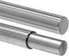
52100 Alloy Steel Splines
|
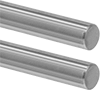 |
Splined on Both Ends |
 |
Splined End × Step-Down End |
 |
4 Splines |
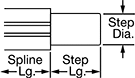 |
Spline | Step, mm | |||||||||
|---|---|---|---|---|---|---|---|---|---|---|
Dia., mm | Lg., mm | No. of | Lg., mm | Root Dia., mm | Dia. | Lg. | Each | |||
Splined on Both Ends | ||||||||||
| 6 | 150 | 4 | 150 | 5.3 | — | — | 61145K61 | 0000000 | ||
| 6 | 200 | 4 | 200 | 5.3 | — | — | 61145K136 | 000000 | ||
| 6 | 300 | 4 | 300 | 5.3 | — | — | 61145K137 | 000000 | ||
| 8 | 150 | 4 | 150 | 7.2 | — | — | 61145K62 | 000000 | ||
| 8 | 200 | 4 | 200 | 7.2 | — | — | 61145K139 | 000000 | ||
| 10 | 200 | 4 | 200 | 9 | — | — | 61145K63 | 000000 | ||
| 10 | 300 | 4 | 300 | 9 | — | — | 61145K144 | 000000 | ||
| 10 | 600 | 4 | 600 | 9 | — | — | 61145K147 | 000000 | ||
| 13 | 200 | 4 | 200 | 11.7 | — | — | 61145K148 | 00000 | ||
| 13 | 500 | 4 | 500 | 11.7 | — | — | 61145K149 | 000000 | ||
| 13 | 700 | 4 | 700 | 11.7 | — | — | 61145K151 | 000000 | ||
| 16 | 200 | 4 | 200 | 14.2 | — | — | 61145K154 | 000000 | ||
| 16 | 700 | 4 | 700 | 14.2 | — | — | 61145K156 | 000000 | ||
| 20 | 200 | 4 | 200 | 17.9 | — | — | 61145K161 | 000000 | ||
| 20 | 2,000 | 4 | 2,000 | 17.9 | — | — | 61145K165 | 000000 | ||
| 25 | 200 | 4 | 200 | 22.4 | — | — | 61145K166 | 000000 | ||
| 25 | 500 | 4 | 500 | 22.4 | — | — | 61145K167 | 000000 | ||
| 30 | 300 | 4 | 300 | 26.8 | — | — | 61145K172 | 000000 | ||
| 30 | 1,000 | 4 | 1,000 | 26.8 | — | — | 61145K174 | 000000 | ||
| 30 | 2,000 | 4 | 2,000 | 26.8 | — | — | 61145K176 | 00000000 | ||
| 40 | 400 | 4 | 400 | 35.5 | — | — | 61145K177 | 000000 | ||
| 40 | 700 | 4 | 700 | 35.5 | — | — | 61145K178 | 000000 | ||
Splined End × Step-Down End | ||||||||||
| 18.2 | 200 | 4 | 350 | 16.4 | 15 | 150 | 61145K86 | 000000 | ||
| 23 | 200 | 4 | 350 | 20.6 | 20 | 150 | 61145K87 | 000000 | ||
| 28 | 300 | 4 | 450 | 24.8 | 25 | 150 | 61145K88 | 000000 | ||
| 37.4 | 400 | 4 | 550 | 33.1 | 30 | 150 | 61145K89 | 000000 | ||
Sleeve Splines and Bearings
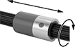 |
Often used in wet and dirty environments, these sleeve splines and bearings create a compact linear and rotary motion system. The grooves on the splines transmit rotary power as the sleeve bearing moves freely along their length. Sleeve bearings don't have moving parts that can be damaged from dirt and debris. And they don't need to be lubricated, making them overall lower maintenance than ball bearings.
Splines
 |
Splines are PTFE coated to reduce friction, so bearings slide smoothly and last longer. They’re stainless steel, so they won’t rust.
Spline | ||||||||||||
|---|---|---|---|---|---|---|---|---|---|---|---|---|
Lg. | No. of | Lg. | Lg. Tolerance | Root Dia. | Material | Edge Type | Hardness Rating | Hardness | Each | |||
1/4" Diameter (Tolerance: -0.002" to 0.002") | ||||||||||||
| 12" | 14 | 12" | 0" to 0.25" | 0.202" | PTFE-Coated 304 Stainless Steel | Straight | Medium | Rockwell B70 | 4134N11 | 000000 | ||
| 24" | 14 | 24" | 0" to 0.25" | 0.202" | PTFE-Coated 304 Stainless Steel | Straight | Medium | Rockwell B70 | 4134N12 | 000000 | ||
| 36" | 14 | 36" | 0" to 0.25" | 0.202" | PTFE-Coated 304 Stainless Steel | Straight | Medium | Rockwell B70 | 4134N13 | 000000 | ||
3/8" Diameter (Tolerance: -0.002" to 0.002") | ||||||||||||
| 12" | 16 | 12" | 0" to 0.25" | 0.306" | PTFE-Coated 304 Stainless Steel | Straight | Medium | Rockwell B70 | 4134N14 | 00000 | ||
| 24" | 16 | 24" | 0" to 0.25" | 0.306" | PTFE-Coated 304 Stainless Steel | Straight | Medium | Rockwell B70 | 4134N15 | 000000 | ||
| 36" | 16 | 36" | 0" to 0.25" | 0.306" | PTFE-Coated 304 Stainless Steel | Straight | Medium | Rockwell B70 | 4134N16 | 000000 | ||
1/2" Diameter (Tolerance: -0.002" to 0.002") | ||||||||||||
| 12" | 18 | 12" | 0" to 0.25" | 0.419" | PTFE-Coated 304 Stainless Steel | Straight | Medium | Rockwell B70 | 4134N17 | 00000 | ||
| 24" | 18 | 24" | 0" to 0.25" | 0.419" | PTFE-Coated 304 Stainless Steel | Straight | Medium | Rockwell B70 | 4134N18 | 000000 | ||
| 36" | 18 | 36" | 0" to 0.25" | 0.419" | PTFE-Coated 304 Stainless Steel | Straight | Medium | Rockwell B70 | 4134N19 | 000000 | ||
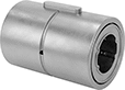
Rounded Bearings
 |
Plastic Bearing—Bearings are plastic with a bronze shell, so they won't rust.
For Spline Dia. | No. of Splines | OD | Overall Lg. | Dynamic Load Cap., lb. | Static Load Cap., lb. | Max. Dynamic Torque | Max. Static Torque | Bearing Material | Shell Material | Each | |||
|---|---|---|---|---|---|---|---|---|---|---|---|---|---|
| 1/4" | 14 | 1/2" | 3/4" | 5 | 5 | Not Rated | Not Rated | Plastic | Bronze | 4134N31 | 000000 | ||
| 3/8" | 16 | 5/8" | 1" | 10 | 10 | Not Rated | Not Rated | Plastic | Bronze | 4134N32 | 00000 | ||
| 1/2" | 18 | 13/16" | 1 1/2" | 15 | 15 | Not Rated | Not Rated | Plastic | Bronze | 4134N33 | 00000 | ||
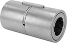
Externally Threaded Bearings
 |
Threaded bearings allow you to mount your load directly to the bearing.
Plastic Bearing—Bearings are plastic with a bronze shell, so they won't rust.
For Spline Dia. | No. of Splines | OD | Overall Lg. | Thread Size | Dynamic Load Cap., lb. | Static Load Cap., lb. | Max. Dynamic Torque | Max. Static Torque | Bearing Material | Shell Material | Each | |||
|---|---|---|---|---|---|---|---|---|---|---|---|---|---|---|
| 1/4" | 14 | 1/2" | 3/4" | 7/16"-20 | 5 | 5 | Not Rated | Not Rated | Plastic | Bronze | 4134N34 | 000000 | ||
| 3/8" | 16 | 5/8" | 1" | 9/16"-20 | 10 | 10 | Not Rated | Not Rated | Plastic | Bronze | 4134N35 | 00000 | ||
| 1/2" | 18 | 13/16" | 1 1/2" | 3/4"-20 | 15 | 15 | Not Rated | Not Rated | Plastic | Bronze | 4134N36 | 00000 | ||
 |
Flanges work with threaded bearings to give you a surface with mounting holes to attach your load.
Anti-Backlash Externally Threaded Bearings
 |
Anti-backlash bearings minimize the space (play) between the bearing and spline for more accurate, repeatable positioning.
Threaded bearings allow you to mount your load directly to the bearing.
Plastic Bearing—Bearings are plastic with a bronze shell, so they won't rust.
For Spline Dia. | No. of Splines | OD | Overall Lg. | Thread Size | Dynamic Load Cap., lb. | Static Load Cap., lb. | Max. Dynamic Torque | Max. Static Torque | Bearing Material | Shell Material | Each | |||
|---|---|---|---|---|---|---|---|---|---|---|---|---|---|---|
| 1/4" | 14 | 1/2" | 3/4" | 7/16"-20 | 5 | 5 | Not Rated | Not Rated | Plastic | Bronze | 4134N41 | 000000 | ||
| 3/8" | 16 | 5/8" | 1" | 9/16"-20 | 10 | 10 | Not Rated | Not Rated | Plastic | Bronze | 4134N42 | 00000 | ||
| 1/2" | 18 | 13/16" | 1 1/2" | 3/4"-20 | 15 | 15 | Not Rated | Not Rated | Plastic | Bronze | 4134N43 | 00000 | ||
|
Flanges work with threaded bearings to give you a surface with mounting holes to attach your load.
Linear Bearings for Ball Splines
 |
Combine these bearings with a ball spline to create a compact linear and rotary motion system for applications with fast, complex movements, such as robotics. These bearings move smoothly and precisely even at high speeds along ball splines while grooves on the ball spline transmit rotary power. Clip a retaining ring into the groove on these bearings to position them in your system. Use the keyway and included machine key for attaching your load.
Steel Bearings
 | |
For 4 Splines |
Groove, mm | Keyway, mm | ||||||||||||||||||
|---|---|---|---|---|---|---|---|---|---|---|---|---|---|---|---|---|---|---|---|
For Spline Dia., mm | For No. of Splines | Overall Lg., mm | OD, mm | Dynamic Load Cap., lb. | Static Load Cap., lb. | Max. Dynamic Torque, in·lbf | Max. Static Torque, in·lbf | Max. Temp., ° F | With Retaining Ring Grooves | Wd. | Dia. | Includes | Lg. | Wd. | Dp. | Each | |||
| 6 | 4 | 25 | 14 | 270 | 510 | 13 | 21 | 176 | Yes | 1.3 | 13.3 | Machine Key | 10.5 | 2.5 | 1.2 | 61145K31 | 000000 | ||
| 8 | 4 | 25 | 16 | 325 | 645 | 18 | 32 | 176 | Yes | 1.3 | 15.3 | Machine Key | 10.5 | 2.5 | 1.2 | 61145K32 | 00000 | ||
| 10 | 4 | 33 | 21 | 610 | 1,100 | 38 | 72 | 176 | Yes | 1.7 | 20 | Machine Key | 13 | 3 | 1.5 | 61145K33 | 00000 | ||
| 13 | 4 | 36 | 24 | 600 | 1,050 | 185 | 346 | 176 | Yes | 1.3 | 22.7 | Machine Key | 15 | 3 | 1.5 | 61145K12 | 00000 | ||
| 16 | 4 | 50 | 31 | 1,350 | 2,500 | 531 | 973 | 176 | Yes | 1.6 | 29.4 | Machine Key | 17.5 | 3.5 | 2 | 61145K13 | 00000 | ||
| 18.2 | 4 | 60 | 32 | 1,750 | 2,500 | 734 | 1,177 | 176 | Yes | 3.1 | 30.2 | Machine Key | 26 | 4 | 2.5 | 61145K36 | 000000 | ||
| 25 | 4 | 71 | 42 | 2,850 | 5,250 | 1,672 | 3,062 | 176 | Yes | 2.5 | 39.5 | Machine Key | 36 | 4 | 2.5 | 61145K15 | 000000 | ||
| 28 | 4 | 80 | 45 | 4,150 | 5,200 | 2,557 | 3,646 | 176 | Yes | 4.15 | 42.6 | Machine Key | 41 | 7 | 4 | 61145K38 | 000000 | ||
| 30 | 4 | 80 | 47 | 4,150 | 5,200 | 2,716 | 3,885 | 176 | Yes | 3 | 44 | Machine Key | 42 | 4 | 2.5 | 61145K16 | 000000 | ||
| 40 | 4 | 100 | 64 | 6,900 | 8,400 | 5,964 | 8,266 | 176 | Yes | 4 | 60 | Machine Key | 52 | 6 | 3.5 | 61145K17 | 000000 | ||
Stainless Steel Bearings
 | |
For 4 Splines |
Groove, mm | Keyway, mm | ||||||||||||||||||
|---|---|---|---|---|---|---|---|---|---|---|---|---|---|---|---|---|---|---|---|
For Spline Dia., mm | For No. of Splines | Overall Lg., mm | OD, mm | Dynamic Load Cap., lb. | Static Load Cap., lb. | Max. Dynamic Torque, in·lbf | Max. Static Torque, in·lbf | Max. Temp., ° F | With Retaining Ring Grooves | Wd. | Dia. | Includes | Lg. | Wd. | Dp. | Each | |||
| 6 | 4 | 25 | 14 | 270 | 510 | 13 | 21 | 176 | Yes | 0.6 | 13.4 | Machine Key | 10.5 | 2.5 | 1.2 | 61145K23 | 0000000 | ||
| 13 | 4 | 36 | 24 | 600 | 1,050 | 185 | 346 | 176 | Yes | 1.3 | 22.7 | Machine Key | 15 | 3 | 1.5 | 61145K26 | 000000 | ||
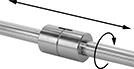
Ball Screw/Splines and Bearings
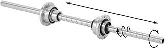 |
From one compact system, transmit linear or rotary motion or both at once (sometimes called spiral motion). Because of these different motions, these ball screw/splines and bearings create efficient, fluid movements in complex automated applications, such as pick-and-place robots.
The ball bearings move smoothly and precisely, even at high speeds. They're powered independently, so you can drive one bearing at a time or both together to coordinate movements.
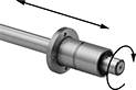
The ball screw/splines are hardened on the surface, so they stand up to repeated motion. They’re also hollow, so you can run electrical wiring, compressed air tubing, coolants, or lubricant through their center.
Spline | Thread | Ball Screw Bearing | Ball Spline Bearing | |||||||||||||||||
|---|---|---|---|---|---|---|---|---|---|---|---|---|---|---|---|---|---|---|---|---|
Lg., mm | No. of | Lg., mm | Direction, ° F | Thread Direction | ID, mm | Lg., mm | Root Dia., mm | OD, mm | Overall Lg., mm | Dynamic Load Cap., lb. | Static Load Cap., lb. | OD, mm | Overall Lg., mm | Dynamic Load Cap., lb. | Static Load Cap., lb. | Max. Dynamic Torque, in·lbf | Each | |||
1055 Carbon Steel | ||||||||||||||||||||
8 mm Dia. (Tolerance: -0.015 mm to 0 mm) | ||||||||||||||||||||
| 200 | 4 | 180 | 5 to 176 | Right Hand | 3 | 200 | 7.44 | 19 | 28.5 | 240 | 400 | 16 | 25 | 330 | 580 | 17 | 4049N11 | 000000000 | ||
10 mm Dia. (Tolerance: -0.015 mm to 0 mm) | ||||||||||||||||||||
| 300 | 4 | 270 | 5 to 176 | Right Hand | 4 | 300 | 9.27 | 23 | 34.5 | 380 | 600 | 21 | 33 | 600 | 1,100 | 34 | 4049N12 | 00000000 | ||
16 mm Dia. (Tolerance: -0.018 mm to 0 mm) | ||||||||||||||||||||
| 500 | 6 | 360 | 5 to 176 | Right Hand | 11 | 500 | 15.15 | 32 | 40 | 870 | 1,610 | 31 | 50 | 1,590 | 2,830 | 277 | 4049N13 | 00000000 | ||
6-Point Impact Sockets with Spline Drive
Black-Oxide Steel
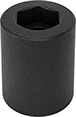 |
Spline Drive |
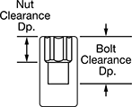 |
Clearance Dp. | Standard Clearance | |||||||||
|---|---|---|---|---|---|---|---|---|---|---|
Drive Size | Nut | Bolt | OD | Socket Shape | For Drive Style | Overall Lg. | Each | |||
No. 5 Spline Drive | ||||||||||
| 7/8" | 9/16" | 1 3/16" | 2 3/8" | 6-Point | External Hex | 3 1/8" | 7932N101 | 000000 | ||
| 15/16" | 9/16" | 1 3/16" | 2 3/8" | 6-Point | External Hex | 3 1/8" | 7932N102 | 00000 | ||
| 1" | 3/4" | 1 3/16" | 2 3/8" | 6-Point | External Hex | 3 1/8" | 7932N103 | 00000 | ||
| 1 1/8" | 1" | 1 3/16" | 2 3/8" | 6-Point | External Hex | 3 1/8" | 7932N104 | 00000 | ||
| 1 1/4" | 1" | 1 3/16" | 2 3/8" | 6-Point | External Hex | 3 1/8" | 7932N105 | 00000 | ||
| 1 5/16" | 11/16" | 1 11/64" | 2 3/8" | 6-Point | External Hex | 3 1/16" | 7932N106 | 00000 | ||
| 1 1/2" | 11/16" | 1 11/64" | 2 5/8" | 6-Point | External Hex | 3 1/16" | 7932N107 | 00000 | ||
| 1 5/8" | 11/16" | 1 11/64" | 2 3/4" | 6-Point | External Hex | 3 1/16" | 7932N108 | 00000 | ||
| 1 3/4" | 1 21/32" | 2 5/32" | 2 7/8" | 6-Point | External Hex | 3 1/16" | 7932N109 | 00000 | ||
| 1 7/8" | 1 9/16" | 2 5/32" | 3 1/64" | 6-Point | External Hex | 3 1/16" | 7932N111 | 00000 | ||
| 2" | 1 43/64" | 2 5/32" | 3 9/64" | 6-Point | External Hex | 3 1/16" | 7932N112 | 00000 | ||
Keyless Locking Rigid Shaft Couplings for Overhung Loads
Steel
 |
For Shaft Dia. | Overall Lg. | OD | Max. Rotation Speed, rpm | Max. Torque, in·lbf | Fastener Tightening Torque, in·lbf | Overhung Load Cap., in·lbf | For Rotary Motion | Each | |||
|---|---|---|---|---|---|---|---|---|---|---|---|
For Keyed, Round, and Splined Shafts | |||||||||||
| 1 1/4" | 1 7/8" | 3" | 10,000 | 8,435 | 104 | 2,105 | Forward/Reverse, Start/Stop, Continuous | 3456N11 | 0000000 | ||
| 1 3/8" | 1 7/8" | 3" | 10,000 | 9,285 | 104 | 2,320 | Forward/Reverse, Start/Stop, Continuous | 3456N12 | 000000 | ||
| 1 1/2" | 2 3/16" | 3 3/4" | 8,000 | 17,160 | 264 | 4,290 | Forward/Reverse, Start/Stop, Continuous | 3456N13 | 000000 | ||
| 1 3/4" | 2 3/16" | 3 3/4" | 8,000 | 20,025 | 264 | 5,005 | Forward/Reverse, Start/Stop, Continuous | 3456N14 | 000000 | ||
| 2" | 2 11/16" | 4 7/16" | 7,700 | 32,685 | 264 | 8,170 | Forward/Reverse, Start/Stop, Continuous | 3456N15 | 000000 | ||
| 2 1/4" | 3 1/16" | 4 3/4" | 7,500 | 44,135 | 264 | 11,030 | Forward/Reverse, Start/Stop, Continuous | 3456N16 | 000000 | ||
| 2 1/2" | 3 1/16" | 4 3/4" | 7,500 | 49,040 | 264 | 12,260 | Forward/Reverse, Start/Stop, Continuous | 3456N17 | 000000 | ||
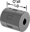
Splined-to-Keyed Flexible Shaft Couplings
 | 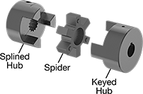 |
(Each Component Sold Separately) |
 |
Diameter |
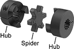
Connect splined shafts to keyed shafts. These couplings are commonly used to connect hydraulic pumps, compressors, and other heavy duty equipment, which often have splined shafts, to electric motors and other components that often have keyed shafts. They have a splined hub on one side and a keyed hub on the other. A spider cushion in the middle damps vibration, absorbs shock loads, and adjusts for misalignment. Because the hubs interlock with the spider, these couplings will continue to work even if the spider breaks or wears away. This fail-safe design gives you time to shut down your power source before damage occurs to other components. Lubrication is not required.
A complete coupling consists of two hubs and one spider. All components are sold separately.
Splined Iron Hubs and Buna-N Spiders—For Forward/Reverse, Start/Stop Motion
Hubs | Keyed Iron Hubs | Buna-N Spiders | ||||||||||||||||
|---|---|---|---|---|---|---|---|---|---|---|---|---|---|---|---|---|---|---|
Misalignment Capability | ||||||||||||||||||
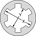
Overall Lg. | OD | Pitch | Pressure Angle | Choose an SAE Spline Size (Diameter X × Diameter Y) | Each | Choose a Shaft Diameter | Each | Max. Rotation Speed, rpm | Max. Torque, in·lbf | Parallel | Angular | Temp. Range, ° F | Spider Material | Each | ||||
| 2 3/16" | 2 7/64" | 0.5" | 30° | A (5/8" × 0.509"), B (7/8" × 0.754") | 9843T101 | 000000 | 3/8", 1/2", 5/8", 3/4", 1" | 3451N801 | 000000 | 9,000 | 140 | 0.015" | 1° | -40 to 212 | Buna-N | 6408K75 | 000000 | |
| 2 7/8" | 2 17/32" | 0.5" | 30° | A (5/8" × 0.509"), B (7/8" × 0.754"), BB (1" × 0.877") | 9843T301 | 00000 | 1/2", 5/8", 3/4", 1", 1 1/8" | 3451N802 | 00000 | 7,000 | 315 | 0.015" | 1° | -40 to 212 | Buna-N | 6408K77 | 00000 | |
| 4 1/2" | 3 3/4" | 0.5" | 30° | A (5/8" × 0.509"), B (7/8" × 0.754"), BB (1" × 0.877"), C (1 1/4" × 1.087"), D (1 3/4" × 1.506"), E (1 3/4" × 1.506") | 9843T601 | 000000 | 5/8", 3/4", 1", 1 1/8", 1 1/4", 1 1/2", 1 3/4" | 3451N803 | 00000 | 5,000 | 1,240 | 0.015" | 1° | -40 to 212 | Buna-N | 6408K81 | 00000 | |
Splined Iron Hubs and Polyurethane Rubber Spiders—For Continuous Motion
Hubs | Keyed Iron Hubs | Polyurethane Spiders | ||||||||||||||||
|---|---|---|---|---|---|---|---|---|---|---|---|---|---|---|---|---|---|---|
Misalignment Capability | ||||||||||||||||||
Overall Lg. | OD | Pitch | Pressure Angle | Choose an SAE Spline Size (Diameter X × Diameter Y) | Each | Choose a Shaft Diameter | Each | Max. Rotation Speed, rpm | Max. Torque, in·lbf | Parallel | Angular | Temp. Range, ° F | Spider Material | Each | ||||
| 2 3/16" | 2 7/64" | 0.5" | 30° | A (5/8" × 0.509"), B (7/8" × 0.754") | 9843T102 | 000000 | 3/8", 1/2", 5/8", 3/4", 1" | 3451N804 | 000000 | 3,600 | 210 | 0.015" | 1° | -30 to 160 | Polyurethane Rubber | 2410K13 | 000000 | |
| 2 7/8" | 2 17/32" | 0.5" | 30° | A (5/8" × 0.509"), B (7/8" × 0.754"), BB (1" × 0.877") | 9843T302 | 00000 | 1/2", 5/8", 3/4", 1", 1 1/8" | 3451N805 | 00000 | 3,600 | 475 | 0.015" | 1° | -30 to 160 | Polyurethane Rubber | 2410K15 | 00000 | |
| 4 1/2" | 3 3/4" | 0.5" | 30° | A (5/8" × 0.509"), B (7/8" × 0.754"), BB (1" × 0.877"), C (1 1/4" × 1.087"), D (1 3/4" × 1.506"), E (1 3/4" × 1.506") | 9843T602 | 000000 | 5/8", 3/4", 1", 1 1/8", 1 1/4", 1 1/2", 1 3/4" | 3451N806 | 00000 | 3,600 | 1,860 | 0.015" | 1° | -30 to 160 | Polyurethane Rubber | 2410K19 | 000000 | |
Splined Iron Hubs and Hytrel Spiders—For Continuous Motion
Hubs | Keyed Iron Hubs | Hytrel Spiders | ||||||||||||||||
|---|---|---|---|---|---|---|---|---|---|---|---|---|---|---|---|---|---|---|
Misalignment Capability | ||||||||||||||||||
Overall Lg. | OD | Pitch | Pressure Angle | Choose an SAE Spline Size (Diameter X × Diameter Y) | Each | Choose a Shaft Diameter | Each | Max. Rotation Speed, rpm | Max. Torque, in·lbf | Parallel | Angular | Temp. Range, ° F | Spider Material | Each | ||||
| 2 3/16" | 2 7/64" | 0.5" | 30° | A (5/8" × 0.509"), B (7/8" × 0.754") | 9843T103 | 000000 | 3/8", 1/2", 5/8", 3/4", 1" | 3451N807 | 000000 | 3,600 | 400 | 0.015" | 0.5° | -55 to 245 | Hytrel | 6408K95 | 000000 | |
| 2 7/8" | 2 17/32" | 0.5" | 30° | A (5/8" × 0.509"), B (7/8" × 0.754"), BB (1" × 0.877") | 9843T303 | 00000 | 1/2", 5/8", 3/4", 1", 1 1/8" | 3451N808 | 00000 | 3,600 | 790 | 0.015" | 0.5° | -55 to 245 | Hytrel | 6408K96 | 000000 | |
| 4 1/2" | 3 3/4" | 0.5" | 30° | A (5/8" × 0.509"), B (7/8" × 0.754"), BB (1" × 0.877"), C (1 1/4" × 1.087"), D (1 3/4" × 1.506"), E (1 3/4" × 1.506") | 9843T603 | 000000 | 5/8", 3/4", 1", 1 1/8", 1 1/4", 1 1/2", 1 3/4" | 3451N809 | 00000 | 3,600 | 3,705 | 0.015" | 0.5° | -55 to 245 | Hytrel | 6408K98 | 000000 | |
Splined Press-Fit Threaded Standoffs
 |  |  |  |
Fully Threaded | Partially Threaded |
Create a secure, permanent hold on sheet metal panels. They're often used to mount access covers and shields onto enclosures. Splines bite into the panels so standoffs don't rotate. Also known as captive standoffs.
Corrosion-Resistant 18-8 Stainless Steel—The choice for wet and outdoor environments, these standoffs resist rusting. They're strong enough for most jobs, but won't withstand stress as well as steel.
Lg. | OD | For Hole Dia. | For Min. Panel Thk. | Threading | Thread Lg. | Min. Thread Lg. | PEM® Part No. | Specs. Met | Pkg. Qty. | Pkg. | |||
|---|---|---|---|---|---|---|---|---|---|---|---|---|---|
Corrosion-Resistant 18-8 Stainless Steel | |||||||||||||
4-40 | |||||||||||||
| 1/4" | 0.219" | 0.166" | 0.06" | Fully Threaded | 1/4" | — | KFSE-440-8 | ASTM A582 | 25 | 92985A110 | 000000 | ||
6-32 | |||||||||||||
| 1/4" | 0.281" | 0.213" | 0.06" | Fully Threaded | 1/4" | — | KFSE-632-8 | ASTM A582 | 25 | 92985A120 | 00000 | ||
| 3/8" | 0.281" | 0.213" | 0.06" | Fully Threaded | 3/8" | — | KFSE-632-12 | ASTM A582 | 10 | 92985A130 | 00000 | ||
| 1/2" | 0.281" | 0.213" | 0.06" | Partially Threaded | — | 3/8" | KFSE-632-16 | ASTM A582 | 10 | 92985A140 | 00000 | ||
Miniature Splined Press-Fit Threaded Standoffs
 |
 |
 |
Fully Threaded |
Lg. | OD | Threading | Thread Lg. | For Hole Dia. | Specs. Met | Pkg. Qty. | Pkg. | |||
|---|---|---|---|---|---|---|---|---|---|---|
Wear-Resistant 400 Series Stainless Steel | ||||||||||
0-80 | ||||||||||
| 3/32" | 0.094" | Fully Threaded | 3/32" | 0.095" | ASTM A380 | 25 | 92985A811 | 00000 | ||
| 1/8" | 0.094" | Fully Threaded | 1/8" | 0.095" | ASTM A380 | 25 | 92985A812 | 0000 | ||
2-56 | ||||||||||
| 3/32" | 0.124" | Fully Threaded | 3/32" | 0.125" | ASTM A380 | 25 | 92985A813 | 0000 | ||
| 1/8" | 0.124" | Fully Threaded | 1/8" | 0.125" | ASTM A380 | 25 | 92985A814 | 0000 | ||
M1 × 0.25 mm | ||||||||||
| 2 mm | 2.4 mm | Fully Threaded | 2 mm | 2.4 mm | ASTM A380 | 25 | 92985A815 | 00000 | ||
| 3 mm | 2.4 mm | Fully Threaded | 3 mm | 2.4 mm | ASTM A380 | 25 | 92985A816 | 00000 | ||
M1.2 × 0.25 mm | ||||||||||
| 2 mm | 2.4 mm | Fully Threaded | 2 mm | 2.4 mm | ASTM A380 | 10 | 92985A220 | 0000 | ||
| 3 mm | 2.4 mm | Fully Threaded | 3 mm | 2.4 mm | ASTM A380 | 10 | 92985A230 | 0000 | ||
M1.4 × 0.3 mm | ||||||||||
| 2 mm | 2.4 mm | Fully Threaded | 2 mm | 2.4 mm | ASTM A380 | 10 | 92985A240 | 0000 | ||
| 3 mm | 2.4 mm | Fully Threaded | 3 mm | 2.4 mm | ASTM A380 | 10 | 92985A250 | 0000 | ||
M1.6 × 0.35 mm | ||||||||||
| 2 mm | 2.4 mm | Fully Threaded | 2 mm | 2.4 mm | ASTM A380 | 25 | 92985A260 | 0000 | ||
| 3 mm | 2.4 mm | Fully Threaded | 3 mm | 2.4 mm | ASTM A380 | 25 | 92985A270 | 0000 | ||
M2 × 0.4 mm | ||||||||||
| 2 mm | 3.2 mm | Fully Threaded | 2 mm | 3.2 mm | ASTM A380 | 25 | 92985A817 | 0000 | ||
| 3 mm | 3.2 mm | Fully Threaded | 3 mm | 3.2 mm | ASTM A380 | 25 | 92985A818 | 0000 | ||
Splined Flexible Shaft Couplings
 |  | |
Components of a Coupling Shown Assembled | (Each Component Sold Separately) | Diameter |
For use with splined shafts, which are commonly found in gearboxes and pumps, these couplings are capable of transmitting more torque than couplings for round and keyed shafts. They have a spider-shaped cushion between two hubs to reduce shock and handle minor shaft misalignment.
A complete coupling consists of two hubs and one spider (each component sold separately). Hubs fasten onto your shafts without damaging them. Tighten the clamping screws to secure.
Buna-N—Buna-N spiders provide good vibration damping and chemical resistance.
Hytrel—Hytrel spiders provide fair vibration damping and excellent chemical resistance.
Polyurethane Rubber—Polyurethane spiders provide fair vibration damping and good chemical resistance.
Hubs | Buna-N Spiders | Hytrel Spiders | Polyurethane Spiders | |||||||||||||||||||||||||||||||
|---|---|---|---|---|---|---|---|---|---|---|---|---|---|---|---|---|---|---|---|---|---|---|---|---|---|---|---|---|---|---|---|---|---|---|
Misalignment Capability | Misalignment Capability | Misalignment Capability | ||||||||||||||||||||||||||||||||
Overall Lg. | OD | For Shaft Type | Pitch | Pressure Angle | For Rotary Motion | Choose an SAE Spline Size (Diameter X × Diameter Y) | Each | Max. Rotation Speed, rpm | Max. Torque, in·lbf | Parallel | Angular | Temp. Range, ° F | Spider Material | Each | Max. Rotation Speed, rpm | Max. Torque, in·lbf | Parallel | Angular | Temp. Range, ° F | Spider Material | Each | Max. Rotation Speed, rpm | Max. Torque, in·lbf | Parallel | Angular | Temp. Range, ° F | Spider Material | Each | ||||||
Iron Hubs | ||||||||||||||||||||||||||||||||||
| 2 3/16" | 2 7/64" | Splined | 0.5" | 30° | Continuous, Forward/Reverse, Start/Stop | A (5/8" × 0.509"), B (7/8" × 0.754") | 9843T1 | 000000 | 9,000 | 140 | 0.015" | 1° | -40 to 212 | Buna-N | 6408K75 | 000000 | 3,600 | 400 | 0.015" | 0.5° | -55 to 245 | Hytrel | 6408K95 | 000000 | 3,600 | 210 | 0.015" | 1° | -30 to 160 | Polyurethane Rubber | 2410K13 | 000000 | ||
| 2 9/16" | 2 7/64" | Splined | 0.5" | 30° | Continuous, Forward/Reverse, Start/Stop | A (5/8" × 0.509"), B (7/8" × 0.754") | 9843T2 | 00000 | 9,000 | 140 | 0.015" | 1° | -40 to 212 | Buna-N | 6408K75 | 00000 | 3,600 | 400 | 0.015" | 0.5° | -55 to 245 | Hytrel | 6408K95 | 00000 | 3,600 | 210 | 0.015" | 1° | -30 to 160 | Polyurethane Rubber | 2410K13 | 00000 | ||
| 2 7/8" | 2 17/32" | Splined | 0.5" | 30° | Continuous, Forward/Reverse, Start/Stop | A (5/8" × 0.509"), B (7/8" × 0.754"), BB (1" × 0.877") | 9843T3 | 00000 | 7,000 | 315 | 0.015" | 1° | -40 to 212 | Buna-N | 6408K77 | 00000 | 3,600 | 790 | 0.015" | 0.5° | -55 to 245 | Hytrel | 6408K96 | 000000 | 3,600 | 475 | 0.015" | 1° | -30 to 160 | Polyurethane Rubber | 2410K15 | 00000 | ||
| 3 1/2" | 2 17/32" | Splined | 0.5" | 30° | Continuous, Forward/Reverse, Start/Stop | A (5/8" × 0.509"), B (7/8" × 0.754"), BB (1" × 0.877") | 9843T4 | 00000 | 7,000 | 315 | 0.015" | 1° | -40 to 212 | Buna-N | 6408K77 | 00000 | 3,600 | 790 | 0.015" | 0.5° | -55 to 245 | Hytrel | 6408K96 | 000000 | 3,600 | 475 | 0.015" | 1° | -30 to 160 | Polyurethane Rubber | 2410K15 | 00000 | ||
| 4 1/4" | 3 21/64" | Splined | 0.5" | 30° | Continuous, Forward/Reverse, Start/Stop | A (5/8" × 0.509"), B (7/8" × 0.754"), BB (1" × 0.877"), C (1 1/4" × 1.087") | 9843T5 | 000000 | 5,000 | 790 | 0.015" | 1° | -40 to 212 | Buna-N | 6408K79 | 00000 | 3,600 | 2,265 | 0.015" | 0.5° | -55 to 245 | Hytrel | 6408K97 | 000000 | 3,600 | 1,185 | 0.015" | 1° | -30 to 160 | Polyurethane Rubber | 2410K17 | 000000 | ||
| 4 1/2" | 3 3/4" | Splined | 0.5" | 30° | Continuous, Forward/Reverse, Start/Stop | A (5/8" × 0.509"), B (7/8" × 0.754"), BB (1" × 0.877"), C (1 1/4" × 1.087"), D (1 3/4" × 1.506"), E (1 3/4" × 1.506") | 9843T6 | 000000 | 5,000 | 1,240 | 0.015" | 1° | -40 to 212 | Buna-N | 6408K81 | 00000 | 3,600 | 3,705 | 0.015" | 0.5° | -55 to 245 | Hytrel | 6408K98 | 000000 | 3,600 | 1,860 | 0.015" | 1° | -30 to 160 | Polyurethane Rubber | 2410K19 | 000000 | ||
