


Filter by
Face Shape

Stroke Length
Face Material
Air Spring Type
Mount Type
Full Stroke Lifting Force @ Pressure
Base Shape
Beginning Stroke Lifting Force @ Pressure
Nose Material
Export Control Classification Number (ECCN)
DFARS Specialty Metals
Adjustable Air Springs
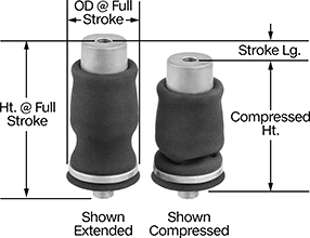
Sleeve Air Spring
 |
Air Inlet | Mount. Hole | Mount. Stud | ||||||||||||||||
|---|---|---|---|---|---|---|---|---|---|---|---|---|---|---|---|---|---|---|
Ht. @ Full Stroke | Compressed Ht. | Stroke Lg. | Extended Ht. | Full Stroke Lifting Force @ Pressure | Beginning Stroke Lifting Force @ Pressure | OD @ Full Stroke | Temp. Range, ° F | Air Spring Material | Thread Type | Gender | Pipe Size | Thread Size | Dp. | Thread Size | Lg. | Each | ||
| 6.88" | 2.2" | 4" | 6.25" | 140 lbf @ 20 psi 320 lbf @ 60 psi 560 lbf @ 100 psi | 250 lbf @ 20 psi 700 lbf @ 60 psi 1,250 lbf @ 100 psi | 5.6" | -20 to 135 | Neoprene | NPTF | Female | 1/8 | 3/8"-16 | 1/2" | 3/4"-16 | 0.63" | 9538K22 | 0000000 | |
| 7.73" | 2.2" | 4.9" | 7.1" | 80 lbf @ 20 psi 180 lbf @ 60 psi 310 lbf @ 100 psi | 340 lbf @ 20 psi 700 lbf @ 60 psi 1,100 lbf @ 100 psi | 4.6" | -20 to 135 | Neoprene | NPTF | Female | 1/8 | 3/8"-16 | 1/2" | 3/4"-16 | 0.63" | 9538K24 | 00000 | |
| 8.72" | 3.6" | 4.4" | 8" | 40 lbf @ 20 psi 60 lbf @ 60 psi 110 lbf @ 100 psi | 60 lbf @ 20 psi 200 lbf @ 60 psi 360 lbf @ 100 psi | 3.25" | -20 to 135 | Neoprene | NPTF | Female | 1/8 | 1/2"-13 | 5/8" | 3/4"-16 | 0.72" | 9538K23 | 00000 | |
| 10.21" | 4" | 5.5" | 9.5" | 160 lbf @ 20 psi 500 lbf @ 60 psi 800 lbf @ 100 psi | 190 lbf @ 20 psi 540 lbf @ 60 psi 950 lbf @ 100 psi | 5.7" | -20 to 135 | Neoprene | NPTF | Female | 1/8 | 1/2"-13 | 5/8" | 3/4"-16 | 0.71" | 9538K28 | 00000 | |
| 11.21" | 4" | 6.5" | 10.5" | 140 lbf @ 20 psi 340 lbf @ 60 psi 540 lbf @ 100 psi | 170 lbf @ 20 psi 520 lbf @ 60 psi 850 lbf @ 100 psi | 4.6" | -20 to 135 | Neoprene | NPTF | Female | 1/8 | 1/2"-13 | 5/8" | 3/4"-16 | 0.71" | 9538K25 | 00000 | |
| 11.21" | 4" | 6.5" | 10.5" | 180 lbf @ 20 psi 460 lbf @ 60 psi 750 lbf @ 100 psi | 230 lbf @ 20 psi 660 lbf @ 60 psi 1,100 lbf @ 100 psi | 5.6" | -20 to 135 | Neoprene | NPTF | Female | 1/8 | 1/2"-13 | 5/8" | 3/4"-16 | 0.71" | 9538K26 | 00000 | |
| 12" | 4.1" | 6.8" | 10.9" | 240 lbf @ 20 psi 700 lbf @ 60 psi 1,200 lbf @ 100 psi | 420 lbf @ 20 psi 1,100 lbf @ 60 psi 2,000 lbf @ 100 psi | 7" | -20 to 135 | Neoprene | NPTF | Female | 1/8 | — | — | — | — | 9538K27 | 000000 | |
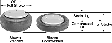
Single-Tire Air Spring
 |
Air Inlet | Mount. Hole | ||||||||||||||||
|---|---|---|---|---|---|---|---|---|---|---|---|---|---|---|---|---|---|
Ht. @ Full Stroke | Compressed Ht. | Stroke Lg. | Extended Ht. | Full Stroke Lifting Force @ Pressure | Beginning Stroke Lifting Force @ Pressure | OD @ Full Stroke | Temp. Range, ° F | Air Spring Material | Thread Type | Gender | Pipe Size | Ctr.-to-Ctr. | Thread Size | Dp. | Each | ||
| 4.8" | 2" | 2.8" | 4.8" | 60 lbf @ 20 psi 440 lbf @ 60 psi 850 lbf @ 100 psi | 420 lbf @ 20 psi 1,200 lbf @ 60 psi 2,000 lbf @ 100 psi | 6.5" | -20 to 135 | Neoprene | NPTF | Female | 1/4 | 1 3/4" | 3/8"-16 | 5/8" | 9539K44 | 0000000 | |
| 5.2" | 2" | 3.2" | 5.2" | 100 lbf @ 20 psi 350 lbf @ 60 psi 850 lbf @ 100 psi | 500 lbf @ 20 psi 1,500 lbf @ 60 psi 2,600 lbf @ 100 psi | 7.7" | -20 to 135 | Neoprene | NPTF | Female | 1/4 | 1 3/4" | 3/8"-16 | 5/8" | 9539K46 | 000000 | |
| 5.3" | 2" | 3.3" | 5.3" | 100 lbf @ 20 psi 550 lbf @ 60 psi 1,100 lbf @ 100 psi | 660 lbf @ 20 psi 2,100 lbf @ 60 psi 3,600 lbf @ 100 psi | 8.7" | -20 to 135 | Neoprene | NPTF | Female | 1/4 | 2 3/4" | 3/8"-16 | 5/8" | 9539K47 | 000000 | |
| 5.4" | 2" | 3.4" | 7.1" | 10 lbf @ 20 psi 300 lbf @ 60 psi 750 lbf @ 100 psi | 750 lbf @ 20 psi 1,800 lbf @ 60 psi 3,000 lbf @ 100 psi | 7" | -20 to 135 | Neoprene | NPTF | Female | 1/4 | 1 3/4" | 3/8"-16 | 5/8" | 9539K49 | 000000 | |
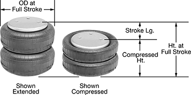
Double-Tire Air Spring
 |
Air Inlet | Mount. Hole | ||||||||||||||||
|---|---|---|---|---|---|---|---|---|---|---|---|---|---|---|---|---|---|
Ht. @ Full Stroke | Compressed Ht. | Stroke Lg. | Extended Ht. | Full Stroke Lifting Force @ Pressure | Beginning Stroke Lifting Force @ Pressure | OD @ Full Stroke | Temp. Range, ° F | Air Spring Material | Thread Type | Gender | Pipe Size | Ctr.-to-Ctr. | Thread Size | Dp. | Each | ||
| 7.1" | 2.8" | 4.3" | 7.7" | 0 lbf @ 20 psi 220 lbf @ 60 psi 580 lbf @ 100 psi | 750 lbf @ 20 psi 1,700 lbf @ 60 psi 2,800 lbf @ 100 psi | 6.5" | -20 to 135 | Neoprene | NPTF | Female | 1/4 | 1 3/4" | 3/8"-16 | 5/8" | 9551K51 | 0000000 | |
| 9 1/2" | 2.9" | 6.6" | 10.1" | 30 lbf @ 20 psi 450 lbf @ 60 psi 1,000 lbf @ 100 psi | 1,200 lbf @ 20 psi 3,100 lbf @ 60 psi 5,000 lbf @ 100 psi | 8.8" | -20 to 135 | Neoprene | NPTF | Female | 1/4 | 2 3/4" | 3/8"-16 | 5/8" | 9551K54 | 000000 | |
Spring-Loaded Guide Plungers
Square Face
 | 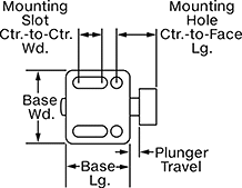 |
Rectangular Base 2 Mounting Slots | 2 Mounting Slots 2 Mounting Holes |
Base | Mounting Slot | Mounting Hole | |||||||||||||||||||||||||||||||||||||||||||||||||||||||||||||||||||||||||||||||||||||||||||||||||
|---|---|---|---|---|---|---|---|---|---|---|---|---|---|---|---|---|---|---|---|---|---|---|---|---|---|---|---|---|---|---|---|---|---|---|---|---|---|---|---|---|---|---|---|---|---|---|---|---|---|---|---|---|---|---|---|---|---|---|---|---|---|---|---|---|---|---|---|---|---|---|---|---|---|---|---|---|---|---|---|---|---|---|---|---|---|---|---|---|---|---|---|---|---|---|---|---|---|---|---|
Face Wd. | Plunger Travel | Shape | Lg. | Wd. | Spring Force, lbf | Body Material | No. of | Lg. | Wd. | Ctr.-to-Ctr. Wd. | No. of | Dia. | Ctr.-to-Ctr. Wd. | Ctr.-to-Face Lg. | Mounting Fasteners Included | Each | |||||||||||||||||||||||||||||||||||||||||||||||||||||||||||||||||||||||||||||||||||
Acetal Face—Adjustable | |||||||||||||||||||||||||||||||||||||||||||||||||||||||||||||||||||||||||||||||||||||||||||||||||||
| 0.39" | 1/8" | Rectangle | 0.65" | 0.866" | 1.8 to 2.4 | Zinc Alloy | 2 | 0.307" | 0.13" | 0.551" | 2 | 0.13" | 0.551" | 0.457" | No | 3351A111 | 00000 | ||||||||||||||||||||||||||||||||||||||||||||||||||||||||||||||||||||||||||||||||||
| 0.39" | 1/8" | Rectangle | 0.65" | 0.866" | 2.5 to 4.5 | Zinc Alloy | 2 | 0.307" | 0.13" | 0.551" | 2 | 0.13" | 0.551" | 0.457" | No | 3351A112 | 0000 | ||||||||||||||||||||||||||||||||||||||||||||||||||||||||||||||||||||||||||||||||||
| 0.63" | 3/16" | Rectangle | 1.083" | 1.25" | 1.8 to 4.2 | Zinc Alloy | 2 | 0.606" | 0.213" | 0.827" | 2 | 0.213" | 0.827" | 0.689" | No | 3351A115 | 00000 | ||||||||||||||||||||||||||||||||||||||||||||||||||||||||||||||||||||||||||||||||||
| 0.63" | 3/16" | Rectangle | 1.083" | 1.25" | 4.3 to 10.1 | Zinc Alloy | 2 | 0.606" | 0.213" | 0.827" | 2 | 0.213" | 0.827" | 0.689" | No | 3351A116 | 00000 | ||||||||||||||||||||||||||||||||||||||||||||||||||||||||||||||||||||||||||||||||||
| 0.87" | 5/16" | Rectangle | 1.375" | 1.5" | 3.9 to 7.4 | Zinc Alloy | 2 | 0.787" | 0.25" | 1.063" | 2 | 0.25" | 1.063" | 0.972" | No | 3351A119 | 00000 | ||||||||||||||||||||||||||||||||||||||||||||||||||||||||||||||||||||||||||||||||||
| 0.87" | 5/16" | Rectangle | 1.375" | 1.5" | 6.1 to 16.8 | Zinc Alloy | 2 | 0.787" | 0.25" | 1.063" | 2 | 0.25" | 1.063" | 0.972" | No | 3351A121 | 00000 | ||||||||||||||||||||||||||||||||||||||||||||||||||||||||||||||||||||||||||||||||||
Stainless Steel Face—Adjustable | |||||||||||||||||||||||||||||||||||||||||||||||||||||||||||||||||||||||||||||||||||||||||||||||||||
| 0.39" | 1/8" | Rectangle | 0.65" | 0.866" | 1.8 to 2.4 | Zinc Alloy | 2 | 0.307" | 0.13" | 0.551" | 2 | 0.13" | 0.551" | 0.457" | No | 3351A113 | 00000 | ||||||||||||||||||||||||||||||||||||||||||||||||||||||||||||||||||||||||||||||||||
| 0.39" | 1/8" | Rectangle | 0.65" | 0.866" | 2.5 to 4.5 | Zinc Alloy | 2 | 0.307" | 0.13" | 0.551" | 2 | 0.13" | 0.551" | 0.457" | No | 3351A114 | 00000 | ||||||||||||||||||||||||||||||||||||||||||||||||||||||||||||||||||||||||||||||||||
| 0.63" | 3/16" | Rectangle | 1.083" | 1.25" | 1.8 to 4.2 | Zinc Alloy | 2 | 0.606" | 0.213" | 0.827" | 2 | 0.213" | 0.827" | 0.689" | No | 3351A117 | 00000 | ||||||||||||||||||||||||||||||||||||||||||||||||||||||||||||||||||||||||||||||||||
| 0.63" | 3/16" | Rectangle | 1.083" | 1.25" | 4.3 to 10.1 | Zinc Alloy | 2 | 0.606" | 0.213" | 0.827" | 2 | 0.213" | 0.827" | 0.689" | No | 3351A118 | 00000 | ||||||||||||||||||||||||||||||||||||||||||||||||||||||||||||||||||||||||||||||||||
| 0.87" | 5/16" | Rectangle | 1.375" | 1.5" | 3.9 to 7.4 | Zinc Alloy | 2 | 0.787" | 0.25" | 1.063" | 2 | 0.25" | 1.063" | 0.972" | No | 3351A122 | 00000 | ||||||||||||||||||||||||||||||||||||||||||||||||||||||||||||||||||||||||||||||||||
| 0.87" | 5/16" | Rectangle | 1.375" | 1.5" | 6.1 to 16.8 | Zinc Alloy | 2 | 0.787" | 0.25" | 1.063" | 2 | 0.25" | 1.063" | 0.972" | No | 3351A123 | 00000 | ||||||||||||||||||||||||||||||||||||||||||||||||||||||||||||||||||||||||||||||||||
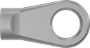
Eyelet Gas Spring End Fittings
 |
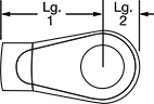 |
Thread Size | ID | Lg. 1 | Lg. 2 | Thk. | Gender | Each | |||||||||||||||||||||||||||||||||||||||||||||||||||||||||||||||||||||||||||||||||||||||||||||
|---|---|---|---|---|---|---|---|---|---|---|---|---|---|---|---|---|---|---|---|---|---|---|---|---|---|---|---|---|---|---|---|---|---|---|---|---|---|---|---|---|---|---|---|---|---|---|---|---|---|---|---|---|---|---|---|---|---|---|---|---|---|---|---|---|---|---|---|---|---|---|---|---|---|---|---|---|---|---|---|---|---|---|---|---|---|---|---|---|---|---|---|---|---|---|---|---|---|---|---|
Zinc | |||||||||||||||||||||||||||||||||||||||||||||||||||||||||||||||||||||||||||||||||||||||||||||||||||
| M6 × 1 mm | 0.208" | 0.709" | 0.35" | 0.39" | Female | 9416K422 | 00000 | ||||||||||||||||||||||||||||||||||||||||||||||||||||||||||||||||||||||||||||||||||||||||||||
| M6 × 1 mm | 0.263" | 0.709" | 0.35" | 0.39" | Female | 9416K423 | 0000 | ||||||||||||||||||||||||||||||||||||||||||||||||||||||||||||||||||||||||||||||||||||||||||||
| M6 × 1 mm | 0.32" | 1.1" | 0.31" | 0.2" | Female | 9416K84 | 0000 | ||||||||||||||||||||||||||||||||||||||||||||||||||||||||||||||||||||||||||||||||||||||||||||
| M6 × 1 mm | 0.41" | 0.83" | 0.42" | 0.39" | Female | 6465K61 | 0000 | ||||||||||||||||||||||||||||||||||||||||||||||||||||||||||||||||||||||||||||||||||||||||||||
| M6 × 1 mm | 0.5" | 1.14" | 0.42" | 0.39" | Female | 6465K112 | 0000 | ||||||||||||||||||||||||||||||||||||||||||||||||||||||||||||||||||||||||||||||||||||||||||||
| M8 × 1.25 mm | 0.32" | 1.1" | 0.31" | 0.2" | Female | 9416K88 | 0000 | ||||||||||||||||||||||||||||||||||||||||||||||||||||||||||||||||||||||||||||||||||||||||||||
| M8 × 1.25 mm | 0.33" | 0.83" | 0.42" | 0.39" | Female | 6465K63 | 0000 | ||||||||||||||||||||||||||||||||||||||||||||||||||||||||||||||||||||||||||||||||||||||||||||
| M8 × 1.25 mm | 0.41" | 0.83" | 0.42" | 0.39" | Female | 6465K27 | 0000 | ||||||||||||||||||||||||||||||||||||||||||||||||||||||||||||||||||||||||||||||||||||||||||||
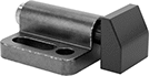
Plate-Mount Retractable Spring Plungers
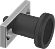 | 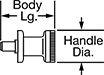 |
Fasten these spring plungers to a flat surface when it's not possible to thread holes. The plate ensures a stable, even base so the spring plunger never shifts out of place. These spring plungers retract manually with a tug of the knob, so you can make controlled adjustments as needed for your job. They're often used for aligning sheet metal parts for cutting, stamping, and welding.
Steel Nose—The strongest, most wear-resistant noses, these won't deform from stress and vibration. Steel is best for dry environments, however, since moisture will cause it to rust.
18-8 Stainless Steel Nose—The choice for wet and outdoor environments, 18-8 stainless steel resists rusting. It's strong enough for most jobs, but won't withstand stress and vibration as well as steel.
Twist-to-Lock—Free up both hands to adjust your workpiece or switch out parts without the plunger springing back and getting in the way. Pull back the handle and twist to lock the nose in its retracted position.
Plate | Nose | Nose Force, lbf | Handle | Mount Holes | Nonlocking | Twist-to-Lock | |||||||||||||||||||||||||||||||||||||||||||||||||||||||||||||||||||||||||||||||||||||||||||||
|---|---|---|---|---|---|---|---|---|---|---|---|---|---|---|---|---|---|---|---|---|---|---|---|---|---|---|---|---|---|---|---|---|---|---|---|---|---|---|---|---|---|---|---|---|---|---|---|---|---|---|---|---|---|---|---|---|---|---|---|---|---|---|---|---|---|---|---|---|---|---|---|---|---|---|---|---|---|---|---|---|---|---|---|---|---|---|---|---|---|---|---|---|---|---|---|---|---|---|---|
Ht. | Wd. | Material | Extended Lg. | Dia. | Extended | Compressed | Body Lg. | Material | Dia. | Dia. | Ctr.-to-Ctr. Wd. | Each | Each | ||||||||||||||||||||||||||||||||||||||||||||||||||||||||||||||||||||||||||||||||||||||
Steel Nose | |||||||||||||||||||||||||||||||||||||||||||||||||||||||||||||||||||||||||||||||||||||||||||||||||||
| 0.71" | 1.57" | Zinc Alloy | 0.24" | 0.24" | 1.9 | 4.9 | 1.46" | Nylon | 1" | 0.17" | 1.18" | 8478A1 | 000000 | 8478A3 | 000000 | ||||||||||||||||||||||||||||||||||||||||||||||||||||||||||||||||||||||||||||||||||||
| 0.71" | 1.57" | Zinc Alloy | 0.55" | 0.24" | 1.9 | 4.9 | 1.77" | Nylon | 1" | 0.17" | 1.18" | 8478A7 | 00000 | 8478A5 | 00000 | ||||||||||||||||||||||||||||||||||||||||||||||||||||||||||||||||||||||||||||||||||||
| 0.79" | 1.81" | Zinc Alloy | 0.31" | 0.31" | 3.5 | 6.3 | 1.73" | Nylon | 1 1/4" | 0.21" | 1.34" | 8478A2 | 00000 | 8478A4 | 00000 | ||||||||||||||||||||||||||||||||||||||||||||||||||||||||||||||||||||||||||||||||||||
| 0.79" | 1.81" | Zinc Alloy | 0.71" | 0.31" | 3.5 | 6.3 | 2.13" | Nylon | 1 1/4" | 0.21" | 1.34" | 8478A8 | 00000 | 8478A6 | 00000 | ||||||||||||||||||||||||||||||||||||||||||||||||||||||||||||||||||||||||||||||||||||
18-8 Stainless Steel Nose | |||||||||||||||||||||||||||||||||||||||||||||||||||||||||||||||||||||||||||||||||||||||||||||||||||
| 0.59" | 1.38" | Zinc Alloy | 0.2" | 0.16" | 0.9 | 2.7 | 1.09" | Nylon | 13/16" | 0.17" | 0.98" | 8478A31 | 00000 | 8478A34 | 00000 | ||||||||||||||||||||||||||||||||||||||||||||||||||||||||||||||||||||||||||||||||||||
| 0.59" | 1.38" | Zinc Alloy | 0.39" | 0.16" | 0.9 | 2.7 | 1.28" | Nylon | 13/16" | 0.17" | 0.98" | 8478A311 | 00000 | 8478A35 | 00000 | ||||||||||||||||||||||||||||||||||||||||||||||||||||||||||||||||||||||||||||||||||||
| 0.71" | 1.57" | Zinc Alloy | 0.24" | 0.2" | 1.3 | 3.6 | 1.34" | Nylon | 1" | 0.17" | 1.18" | 8478A312 | 00000 | 8478A36 | 00000 | ||||||||||||||||||||||||||||||||||||||||||||||||||||||||||||||||||||||||||||||||||||
| 0.71" | 1.57" | Zinc Alloy | 0.24" | 0.24" | 1.3 | 3.6 | 1.34" | Nylon | 1" | 0.17" | 1.18" | 8478A314 | 00000 | 8478A38 | 00000 | ||||||||||||||||||||||||||||||||||||||||||||||||||||||||||||||||||||||||||||||||||||
| 0.71" | 1.57" | Zinc Alloy | 0.24" | 0.24" | 1.9 | 4.9 | 1.46" | Nylon | 1" | 0.17" | 1.18" | 8478A11 | 00000 | 8478A21 | 00000 | ||||||||||||||||||||||||||||||||||||||||||||||||||||||||||||||||||||||||||||||||||||
| 0.71" | 1.57" | Zinc Alloy | 0.47" | 0.2" | 1.3 | 3.6 | 1.57" | Nylon | 1" | 0.17" | 1.18" | 8478A313 | 00000 | 8478A37 | 00000 | ||||||||||||||||||||||||||||||||||||||||||||||||||||||||||||||||||||||||||||||||||||
| 0.71" | 1.57" | Zinc Alloy | 0.47" | 0.24" | 1.3 | 3.6 | 1.57" | Nylon | 1" | 0.17" | 1.18" | 8478A315 | 00000 | 8478A39 | 00000 | ||||||||||||||||||||||||||||||||||||||||||||||||||||||||||||||||||||||||||||||||||||
| 0.71" | 1.57" | Zinc Alloy | 0.55" | 0.24" | 1.9 | 4.9 | 1.77" | Nylon | 1" | 0.17" | 1.18" | 8478A12 | 00000 | 8478A22 | 00000 | ||||||||||||||||||||||||||||||||||||||||||||||||||||||||||||||||||||||||||||||||||||
| 0.79" | 1.81" | Zinc Alloy | 0.31" | 0.31" | 3.5 | 6.3 | 1.73" | Nylon | 1 1/4" | 0.21" | 1.34" | 8478A13 | 00000 | 8478A23 | 00000 | ||||||||||||||||||||||||||||||||||||||||||||||||||||||||||||||||||||||||||||||||||||
| 0.79" | 1.81" | Zinc Alloy | 0.71" | 0.31" | 3.5 | 6.3 | 2.13" | Nylon | 1 1/4" | 0.21" | 1.34" | 8478A14 | 00000 | 8478A24 | 00000 | ||||||||||||||||||||||||||||||||||||||||||||||||||||||||||||||||||||||||||||||||||||
| 0.91" | 1.97" | Zinc Alloy | 0.39" | 0.31" | 2.4 | 7.8 | 1.87" | Nylon | 1 5/16" | 0.21" | 1.5" | 8478A316 | 00000 | 8478A41 | 00000 | ||||||||||||||||||||||||||||||||||||||||||||||||||||||||||||||||||||||||||||||||||||
| 0.91" | 1.97" | Zinc Alloy | 0.39" | 0.39" | 2.4 | 7.8 | 1.87" | Nylon | 1 5/16" | 0.21" | 1.5" | 8478A318 | 00000 | 8478A43 | 00000 | ||||||||||||||||||||||||||||||||||||||||||||||||||||||||||||||||||||||||||||||||||||
| 0.91" | 1.97" | Zinc Alloy | 0.79" | 0.31" | 2.4 | 7.8 | 2.27" | Nylon | 1 5/16" | 0.21" | 1.5" | 8478A317 | 00000 | 8478A42 | 00000 | ||||||||||||||||||||||||||||||||||||||||||||||||||||||||||||||||||||||||||||||||||||
| 0.91" | 1.97" | Zinc Alloy | 0.79" | 0.39" | 2.4 | 7.8 | 2.27" | Nylon | 1 5/16" | 0.21" | 1.5" | 8478A319 | 00000 | 8478A44 | 00000 | ||||||||||||||||||||||||||||||||||||||||||||||||||||||||||||||||||||||||||||||||||||
