


About Gears
More
About Roller Chain and Sprockets
More
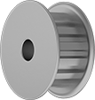
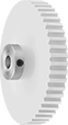
Lightweight Sprockets for ANSI Roller Chain
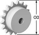
Made of nylon, these sprockets are lightweight, quiet, and corrosion resistant. They come machined to the shaft diameter size listed and are machinable up to the maximum shaft diameter size.
![]() For technical drawings and 3-D models, click on a part number.
For technical drawings and 3-D models, click on a part number.
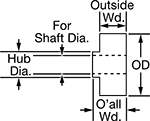
| Number of Teeth | For Shaft Dia. | For Max. Shaft Dia. | OD | Overall Wd. | Hub Dia. | Material | Each | |
For ANSI 25 Roller Chain (1/4" Pitch) | ||||||||
|---|---|---|---|---|---|---|---|---|
| 14 | 5/16" | 1/2" | 1.25" | 31/64" | 3/4" | Nylon Plastic | 000000000 | 000000 |
| 15 | 5/16" | 1/2" | 1.33" | 31/64" | 3/4" | Nylon Plastic | 000000000 | 00000 |
| 16 | 5/16" | 1/2" | 1.41" | 31/64" | 13/16" | Nylon Plastic | 000000000 | 00000 |
| 17 | 5/16" | 1/2" | 1.49" | 31/64" | 29/32" | Nylon Plastic | 000000000 | 00000 |
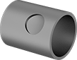
Quick-Grip Screw-Clamp Bushings

Also known as Trantorque bushings, these tighten with a twist of the collar nut—no screws needed. As you tighten the collar nut, the inner sleeve contracts onto the shaft and the outer sleeve expands to hold your sprocket, pulley, or gear.
![]() For technical drawings and 3-D models, click on a part number.
For technical drawings and 3-D models, click on a part number.
| For Shaft Dia. | OD | Overall Wd. | Max. Torque, in.-lbs. | Each | |
Steel | |||||
|---|---|---|---|---|---|
| 5/16" | 3/4" | 7/8" | 360 | 0000000 | 000000 |
Light Duty Sleeve Bushings
Reduce the ID of sprockets, pulleys, and gears in low-torque applications. Bushings have a hole for a set screw.
![]() For technical drawings and 3-D models, click on a part number.
For technical drawings and 3-D models, click on a part number.
| For Shaft Dia. | OD | Overall Wd. | Set Screw Hole Dia. | Material | Each | |
| 5/16" | 1/2" | 1 1/8" | 3/8" | Steel | 0000000 | 00000 |
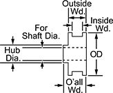
XL Series Corrosion-Resistant Timing Belt Pulleys
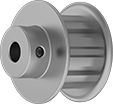
Pulleys are anodized aluminum, which is more corrosion resistant than steel. They are XL series (extra light) and have trapezoidal teeth. Select a pulley with a maximum belt width that’s the same or larger than your timing belt width.
For tight spots, choose a pulley without a hub.
![]() For technical drawings and 3-D models, click on a part number.
For technical drawings and 3-D models, click on a part number.
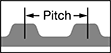
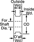
| OD | Number of Teeth | Pitch | For Shaft Dia. | Bore Type | Inside Wd. | Outside Wd. | Overall Wd. | Pitch Dia. | Fabrication | Material | Hub Dia. | Each | |
For 1/4" Max. Belt Wd. | |||||||||||||
|---|---|---|---|---|---|---|---|---|---|---|---|---|---|
With Hub—Two Flanges | |||||||||||||
| 1.625" | 22 | 0.200" | 5/16" | Finished | 0.31" | 0.438" | 0.75" | 1.401" | Machined | Anodized Aluminum | 1" | 0000000 | 000000 |
| 1.75" | 24 | 0.200" | 5/16" | Finished | 0.31" | 0.438" | 0.781" | 1.528" | Machined | Anodized Aluminum | 1.062" | 0000000 | 00000 |
| 1.875" | 26 | 0.200" | 5/16" | Finished | 0.31" | 0.438" | 0.781" | 1.655" | Machined | Anodized Aluminum | 1.188" | 0000000 | 00000 |
| 2" | 28 | 0.200" | 5/16" | Finished | 0.31" | 0.438" | 0.781" | 1.783" | Machined | Anodized Aluminum | 1.188" | 0000000 | 00000 |
For 3/8" Max. Belt Wd. | |||||||||||||
With Hub | |||||||||||||
| 2.017" | 32 | 0.200" | 5/16" | Finished | __ | 0.563" | 1" | 2.037" | Machined | Anodized Aluminum | 1.5" | 0000000 | 00000 |
| 2.272" | 36 | 0.200" | 5/16" | Finished | __ | 0.563" | 1" | 2.292" | Machined | Anodized Aluminum | 1.5" | 0000000 | 00000 |
| 2.526" | 40 | 0.200" | 5/16" | Finished | __ | 0.563" | 1" | 2.546" | Machined | Anodized Aluminum | 1.5" | 0000000 | 00000 |
| 2.654" | 42 | 0.200" | 5/16" | Finished | __ | 0.563" | 1" | 2.674" | Machined | Anodized Aluminum | 1.5" | 0000000 | 00000 |
| 2.781" | 44 | 0.200" | 5/16" | Finished | __ | 0.563" | 1" | 2.801" | Machined | Anodized Aluminum | 1.5" | 0000000 | 00000 |
| 3.036" | 48 | 0.200" | 5/16" | Finished | __ | 0.563" | 1" | 3.056" | Machined | Anodized Aluminum | 1.5" | 000000 | 00000 |
Without Hub—Two Flanges | |||||||||||||
| 1.094" | 14 | 0.200" | 5/16" | Finished | 0.429" | 0.563" | 0.563" | 0.891" | Machined | Anodized Aluminum | __ | 00000000 | 00000 |
| 1.188" | 15 | 0.200" | 5/16" | Finished | 0.429" | 0.563" | 0.563" | 0.955" | Machined | Anodized Aluminum | __ | 00000000 | 00000 |
| 1.25" | 16 | 0.200" | 5/16" | Finished | 0.429" | 0.563" | 0.563" | 1.019" | Machined | Anodized Aluminum | __ | 00000000 | 00000 |
| 1.312" | 18 | 0.200" | 5/16" | Finished | 0.429" | 0.563" | 0.563" | 1.146" | Machined | Anodized Aluminum | __ | 00000000 | 00000 |
| 1.5" | 20 | 0.200" | 5/16" | Finished | 0.429" | 0.563" | 0.563" | 1.273" | Machined | Anodized Aluminum | __ | 00000000 | 00000 |
| 1.625" | 22 | 0.200" | 5/16" | Finished | 0.429" | 0.563" | 0.563" | 1.401" | Machined | Anodized Aluminum | __ | 00000000 | 00000 |
| 1.75" | 24 | 0.200" | 5/16" | Finished | 0.429" | 0.563" | 0.563" | 1.528" | Machined | Anodized Aluminum | __ | 00000000 | 00000 |
| 2.125" | 30 | 0.200" | 5/16" | Finished | 0.429" | 0.563" | 0.563" | 1.91" | Machined | Anodized Aluminum | __ | 00000000 | 00000 |
| 2.25" | 32 | 0.200" | 5/16" | Finished | 0.429" | 0.563" | 0.563" | 2.037" | Machined | Anodized Aluminum | __ | 00000000 | 00000 |
XL Series Lightweight Timing Belt Pulleys
Acetal and aluminum construction makes these pulleys useful in weight-sensitive applications. All are XL series (extra light) and have trapezoidal teeth. Select a pulley with a maximum belt width that’s the same or larger than your timing belt width.
![]() For technical drawings and 3-D models, click on a part number.
For technical drawings and 3-D models, click on a part number.


Hub | |||||||||||||||
|---|---|---|---|---|---|---|---|---|---|---|---|---|---|---|---|
| OD | Number of Teeth | Pitch | For Shaft Dia. | Bore Type | Inside Wd. | Outside Wd. | Overall Wd. | Pitch Dia. | Number of Flanges | Fabrication | Material | Material | Dia. | Each | |
For 3/8" Max. Belt Wd. | |||||||||||||||
Inch | |||||||||||||||
| 1.75" | 24 | 0.200" | 5/16" | Finished | 0.5" | 0.625" | 0.813" | 1.528" | 2 | Molded | Acetal | Aluminum | 0.875" | 00000000 | 000000 |
| 1.88" | 26 | 0.200" | 5/16" | Finished | 0.5" | 0.625" | 0.813" | 1.655" | 2 | Molded | Acetal | Aluminum | 0.875" | 00000000 | 00000 |
| 2" | 28 | 0.200" | 5/16" | Finished | 0.5" | 0.625" | 0.813" | 1.783" | 2 | Molded | Acetal | Aluminum | 0.875" | 00000000 | 00000 |
| 2.13" | 30 | 0.200" | 5/16" | Finished | 0.5" | 0.625" | 0.813" | 1.91" | 2 | Molded | Acetal | Aluminum | 0.875" | 00000000 | 00000 |
| 2.25" | 32 | 0.200" | 5/16" | Finished | 0.5" | 0.625" | 0.813" | 2.037" | 2 | Molded | Acetal | Aluminum | 0.875" | 00000000 | 00000 |
| 2.53" | 36 | 0.200" | 5/16" | Finished | 0.5" | 0.625" | 0.813" | 2.292" | 2 | Molded | Acetal | Aluminum | 0.875" | 00000000 | 00000 |
| 2.75" | 40 | 0.200" | 5/16" | Finished | 0.5" | 0.625" | 0.813" | 2.546" | 2 | Molded | Acetal | Aluminum | 0.875" | 00000000 | 00000 |
| 2.91" | 42 | 0.200" | 5/16" | Finished | 0.5" | 0.625" | 0.813" | 2.674" | 2 | Molded | Acetal | Aluminum | 0.875" | 00000000 | 00000 |
| 3.03" | 44 | 0.200" | 5/16" | Finished | 0.5" | 0.625" | 0.813" | 2.801" | 2 | Molded | Acetal | Aluminum | 0.875" | 00000000 | 00000 |
| 3.28" | 48 | 0.200" | 5/16" | Finished | 0.5" | 0.625" | 0.813" | 3.056" | 2 | Molded | Acetal | Aluminum | 0.875" | 00000000 | 00000 |
| 3.8" | 60 | 0.200" | 5/16" | Finished | __ | 0.688" | 0.813" | 3.82" | __ | Molded | Acetal | Aluminum | 0.875" | 00000000 | 00000 |
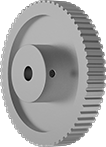
XL Series Timing Belt Pulleys
Pulleys are XL series (extra light) and have trapezoidal teeth. Select a pulley with a maximum belt width that’s the same or larger than your timing belt width.
![]() For technical drawings and 3-D models, click on a part number.
For technical drawings and 3-D models, click on a part number.

| OD | Number of Teeth | Pitch | For Shaft Dia. | Bore Type | Inside Wd. | Outside Wd. | Overall Wd. | Pitch Dia. | Number of Flanges | Fabrication | Hub Dia. | Each | |
For 3/8" Max. Belt Wd. | |||||||||||||
|---|---|---|---|---|---|---|---|---|---|---|---|---|---|
| 2.017" | 32 | 0.200" | 5/16" | Finished | __ | 0.563" | 1" | 2.037" | __ | Sintered | 1.5" | 00000000 | 000000 |
| 2.138" | 30 | 0.200" | 5/16" | Finished | 0.422" | 0.563" | 0.875" | 1.91" | 2 | Sintered | 1.375" | 00000000 | 00000 |
| 2.272" | 36 | 0.200" | 5/16" | Finished | __ | 0.563" | 1" | 2.292" | __ | Sintered | 1.5" | 00000000 | 00000 |
| 2.526" | 40 | 0.200" | 5/16" | Finished | __ | 0.563" | 1" | 2.546" | __ | Sintered | 1.5" | 00000000 | 00000 |
| 2.654" | 42 | 0.200" | 5/16" | Finished | __ | 0.563" | 1" | 2.674" | __ | Sintered | 1.5" | 00000000 | 00000 |
| 2.781" | 44 | 0.200" | 5/16" | Finished | __ | 0.563" | 1" | 2.801" | __ | Sintered | 1.5" | 00000000 | 00000 |
| 3.036" | 48 | 0.200" | 5/16" | Finished | __ | 0.563" | 1" | 3.056" | __ | Sintered | 1.5" | 00000000 | 00000 |
| OD | Number of Teeth | Pitch | For Shaft Dia. | Bore Type | Inside Wd. | Outside Wd. | Overall Wd. | Pitch Dia. | Number of Flanges | Fabrication | Hub Dia. | Each | |
For 3/8" Max. Belt Wd. | |||||||||||||
|---|---|---|---|---|---|---|---|---|---|---|---|---|---|
| 1" | 12 | 0.200" | 5/16" | Finished | 0.43" | 0.563" | 0.812" | 0.764" | 2 | Machined | 0.5" | 00000000 | 000000 |
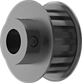
High-Strength Corrosion-Resistant HTD Timing Belt Pulleys
Move belts forward and backward or stop and start them in precise positions, especially in areas where rust is a concern. The curved teeth on these high-torque drive (HTD) pulleys have more surface contact with belts than traditional trapezoidal teeth, which allows you to apply more torque without damaging belts. These teeth fit together seamlessly to prevent backlash, or unwanted movement of the belt on the pulley, for a smooth, quiet cycle. These pulleys are often used in 3D printing, machine tool drives, robotics, and other applications where precision is essential. They are also known as curvilinear belt pulleys.
Pair pulleys with an HTD timing belt that has the same pitch. The width of your belt should not be larger than the maximum belt width listed.
Aluminum pulleys will not rust in damp or humid environments, but water left on the surface will cause them to corrode.
![]() For technical drawings and 3-D models, click on a part number.
For technical drawings and 3-D models, click on a part number.
High-Strength GT Timing Belt Pulleys
For higher speed or higher torque applications, these GT series timing belt pulleys provide a more precise fit than HTD pulleys. Use them where accuracy is critical, such as in storage and retrieval systems or in robotics. Similar to HTD timing belt pulleys, their teeth are curved for high strength. The curved teeth create positive grip engagement with timing belts, so these pulleys do not require re-tensioning—unlike drives using V-belts or sheaves. And unlike chain drives, there’s no metal-on-metal contact, so these pulleys don’t require lubrication.
Anodized aluminum pulleys are lightweight and resist corrosion. They have a finished bore and come with set screws for mounting on shafts.
![]() For technical drawings and 3-D models, click on a part number.
For technical drawings and 3-D models, click on a part number.
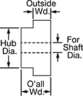
| Number of Teeth | Pitch, mm | For Shaft Diameter | Bore Type | Outside Width, mm | Overall Width, mm | Pitch Diameter, mm | Fabrication | Material | Hub Diameter, mm | Each | |
For 6 mm Maximum Belt Width | |||||||||||
|---|---|---|---|---|---|---|---|---|---|---|---|
| 100 | 2 | 5/16" | Finished | 9.65 | 19.05 | 63.652 | Machined | Anodized Aluminum | 38.1 | 00000000 | 000000 |
For 9 mm Maximum Belt Width | |||||||||||
| 48 | 3 | 5/16" | Finished | 12.7 | 22.26 | 45.807 | Machined | Anodized Aluminum | 31.75 | 00000000 | 00000 |
| 50 | 3 | 5/16" | Finished | 12.7 | 22.26 | 47.752 | Machined | Anodized Aluminum | 31.75 | 00000000 | 00000 |
| 56 | 3 | 5/16" | Finished | 12.7 | 22.26 | 53.467 | Machined | Anodized Aluminum | 31.75 | 00000000 | 00000 |
| 60 | 3 | 5/16" | Finished | 12.7 | 22.26 | 57.302 | Machined | Anodized Aluminum | 31.75 | 00000000 | 00000 |
| 72 | 3 | 5/16" | Finished | 12.7 | 22.26 | 68.758 | Machined | Anodized Aluminum | 31.75 | 00000000 | 00000 |
| 80 | 3 | 5/16" | Finished | 12.7 | 22.26 | 76.403 | Machined | Anodized Aluminum | 31.75 | 00000000 | 00000 |
| 90 | 3 | 5/16" | Finished | 12.7 | 22.26 | 85.954 | Machined | Anodized Aluminum | 31.75 | 00000000 | 00000 |
| 100 | 3 | 5/16" | Finished | 12.7 | 22.26 | 95.504 | Machined | Anodized Aluminum | 31.75 | 0000000 | 00000 |
| 120 | 3 | 5/16" | Finished | 12.7 | 22.26 | 114.579 | Machined | Anodized Aluminum | 31.75 | 00000000 | 00000 |
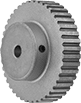
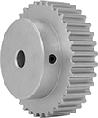
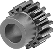
Metal Gears and Gear Racks—20° Pressure Angle
The current industry standard, these 20° pressure angle gears have thicker, stronger teeth than 14½° pressure angle gears. Compared to plastic gears and racks, they’re better for high-load, high-speed, and heavy duty applications. Also known as spur gears.
Combine gears with different numbers of teeth to change speed and torque in your assembly. Combine a gear and rack to convert rotary motion into linear motion. To minimize your footprint, mount one or more standard gears inside of an internal gear.
For components to mesh correctly, they must have the same pressure angle and pitch/module.
Brass gears and racks are easy to machine, so you can add your own mounting holes and make other alterations. They won't rust when exposed to water.
Carbon steel components have hard, strong, and wear-resistant teeth, although they will rust when exposed to moisture and corrosive chemicals. They're best for high-torque machines, like lifting equipment, and heavy duty applications, such as rock crushing. Gears with teeth that are not hardened can be hardened to fit your application.
![]() For technical drawings and 3-D models, click on a part number.
For technical drawings and 3-D models, click on a part number.
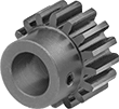
Metal Gears and Gear Racks—14 1/2° Pressure Angle
A former industry standard, 14½° pressure angle gears are often found on older machinery. Made of carbon steel, they have high strength and are better than plastic gears and gear racks for high-load, high-speed, and heavy duty applications.
Combine gears with different numbers of teeth to change speed and torque in your assembly. Combine a gear and rack to convert rotary motion into linear motion.
For components to mesh correctly, they must have the same pressure angle and pitch.
Gears with hardened teeth are more wear resistant than gears with teeth that are not hardened. Gears with teeth that are not hardened can be hardened to fit your application. Hardening a gear's teeth increases its wear resistance.
![]() For technical drawings and 3-D models, click on a part number.
For technical drawings and 3-D models, click on a part number.

Hub | |||||||||||||
|---|---|---|---|---|---|---|---|---|---|---|---|---|---|
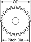
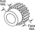
| Gear Pitch | Number of Teeth | Gear Pitch Dia. | OD | Face Wd. | Overall Wd. | For Shaft Dia. | Material | Teeth Heat Treatment | Dia. | Wd. | Set Screw Thread Size | Each | |
Round Bore | |||||||||||||
| 32 | 24 | 3/4" | 0.81" | 3/16" | 0.5" | 5/16" | 1144 Carbon Steel | Not Hardened | 0.656" | 0.313" | __ | 0000000 | 000000 |
| 24 | 16 | 0.666" | 0.75" | 1/4" | 0.563" | 5/16" | 1144 Carbon Steel | Not Hardened | 0.547" | 0.313" | __ | 0000000 | 00000 |
| 24 | 20 | 0.833" | 0.92" | 1/4" | 0.563" | 5/16" | 1144 Carbon Steel | Not Hardened | 0.719" | 0.313" | __ | 0000000 | 00000 |
| 20 | 12 | 0.6" | 0.7" | 3/8" | 0.75" | 5/16" | 1144 Carbon Steel | Hardened | 0.469" | 0.375" | __ | 00000000 | 00000 |
| 20 | 12 | 0.6" | 0.7" | 3/8" | 0.75" | 5/16" | 1144 Carbon Steel | Not Hardened | 0.469" | 0.375" | __ | 0000000 | 00000 |
Round Bore with Set Screw | |||||||||||||
| 24 | 20 | 0.833" | 0.92" | 1/4" | 0.563" | 5/16" | 1144 Carbon Steel | Not Hardened | 0.719" | 0.313" | 10-24 | 0000000 | 00000 |
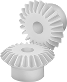
Metal Miter Gears


With straight, conically shaped teeth and a 1:1 speed ratio, miter gears connect two shafts at an angle without changing shaft speed or torque. They're more efficient than spiral miter gears because they create less friction.
For two gears to mesh correctly, they must have the same pressure angle, shaft angle, pitch/module, and number of teeth.
Carbon steel gears have hard, strong, and wear-resistant teeth. They’re best for heavy duty and high-torque applications, such as lifting equipment. However, these gears will rust when exposed to moisture or corrosive chemicals. Some gears have hardened teeth for additional wear resistance; gears with teeth that are not hardened can be hardened to fit your application.
![]() For technical drawings and 3-D models, click on a part number.
For technical drawings and 3-D models, click on a part number.
Hub | ||||||||||||||
|---|---|---|---|---|---|---|---|---|---|---|---|---|---|---|
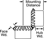
| Gear Pitch | Number of Teeth | For Shaft Angle | Pressure Angle | Gear Pitch Dia. | OD | Face Wd. | Overall Wd. | For Shaft Dia. | Mounting Distance | Teeth Heat Treatment | Dia. | Wd. | Each | |
Round Bore—1117 Carbon Steel | ||||||||||||||
| 16 | 12 | 90° | 20° | 3/4" | 0.84" | 0.16" | 0.583" | 5/16" | 0.812" | Not Hardened | 0.62" | 0.38" | 0000000 | 000000 |
Plastic Gears and Gear Racks—20° Pressure Angle
The current industry standard, these 20° pressure angle gears have thicker, stronger teeth than 14½° pressure angle gears. Made of plastic, they run quieter than metal gears and have good corrosion and chemical resistance. They’re also known as spur gears.
Combine gears with different numbers of teeth to change speed and torque in your assembly. Combine a gear and rack to convert rotary motion into linear motion.
For components to mesh correctly, they must have the same pressure angle and pitch/module.
Acetal gears are best suited for use in light duty machines or for prototyping.
![]() For technical drawings and 3-D models, click on a part number.
For technical drawings and 3-D models, click on a part number.

Hub | |||||||||||||
|---|---|---|---|---|---|---|---|---|---|---|---|---|---|
| Gear Pitch | Number of Teeth | Gear Pitch Dia. | OD | Face Wd. | Overall Wd. | For Shaft Dia. | Material | Fabrication | Color | Dia. | Wd. | Each | |
Round Bore | |||||||||||||
| 32 | 96 | 3" | 3.06" | 3/16" | 0.5" | 5/16" | Acetal Plastic | Molded | White | 0.813" | 0.313" | 0000000 | 00000 |
| 24 | 48 | 2" | 2.08" | 1/4" | 0.563" | 5/16" | Acetal Plastic | Molded | White | 0.672" | 0.313" | 0000000 | 0000 |
| 24 | 60 | 2 1/2" | 2.58" | 1/4" | 0.563" | 5/16" | Acetal Plastic | Molded | White | 0.672" | 0.313" | 0000000 | 0000 |
Plastic Miter Gears
Connect two shafts at a right angle without changing shaft speed or torque. Made of plastic, these gears run quieter than metal gears and have good corrosion and chemical resistance.
For two gears to mesh correctly, they must have the same pressure angle, pitch/module, and number of teeth.
Nylon gears are self-lubricating, so they’re often used in food machinery. However, they’re not approved for direct contact with food or chemicals that will come into contact with food.
![]() For technical drawings and 3-D models, click on a part number.
For technical drawings and 3-D models, click on a part number.

Hub | |||||||||||||||
|---|---|---|---|---|---|---|---|---|---|---|---|---|---|---|---|
| Gear Pitch | Number of Teeth | Pressure Angle | Gear Pitch Dia. | OD | Face Wd. | Overall Wd. | For Shaft Dia. | Mounting Distance | Material | Fabrication | Color | Dia. | Wd. | Each | |
Round Bore | |||||||||||||||
| 24 | 36 | 20° | 1 1/2" | 1.56" | 0.21" | 0.609" | 5/16" | 1.188" | Nylon Plastic | Molded | White | 0.688" | 0.313" | 0000000 | 000000 |