


About Roller Chain and Sprockets
More
About Gears
More
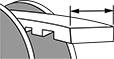
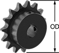
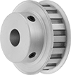
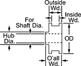
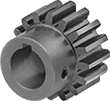
Sprockets for ANSI Roller Chain
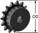
Mount these sprockets onto your shaft and secure with a set screw—no machining necessary.
![]() For technical drawings and 3-D models, click on a part number.
For technical drawings and 3-D models, click on a part number.
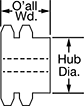
Keyway | ||||||||||
|---|---|---|---|---|---|---|---|---|---|---|
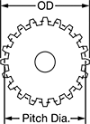
| Number of Teeth | For Shaft Dia. | OD | Overall Wd. | Hub Dia. | Wd. | Dp. | Material | Includes | Each | |
| 35 | 5/8" | 4.39" | 7/8" | 2 1/4" | 3/16" | 3/32" | Steel | Two Set Screws | 00000000 | 000000 |
| 35 | 3/4" | 4.39" | 7/8" | 2 1/4" | 3/16" | 3/32" | Steel | Two Set Screws | 00000000 | 00000 |
| 35 | 7/8" | 4.39" | 7/8" | 2 1/4" | 3/16" | 3/32" | Steel | Two Set Screws | 00000000 | 00000 |
| 35 | 1" | 4.39" | 7/8" | 2 1/4" | 1/4" | 1/8" | Steel | Two Set Screws | 00000000 | 00000 |
| 35 | 1 1/8" | 4.39" | 7/8" | 2 1/4" | 1/4" | 1/8" | Steel | Two Set Screws | 00000000 | 00000 |
| 35 | 1 3/16" | 4.39" | 7/8" | 2 1/4" | 1/4" | 1/8" | Steel | Two Set Screws | 00000000 | 00000 |
| 35 | 1 1/4" | 4.39" | 7/8" | 2 1/4" | 1/4" | 1/8" | Steel | Two Set Screws | 00000000 | 00000 |
| 36 | 5/8" | 4.51" | 7/8" | 2 1/4" | 3/16" | 3/32" | Steel | Two Set Screws | 00000000 | 00000 |
| 36 | 3/4" | 4.51" | 7/8" | 2 1/4" | 3/16" | 3/32" | Steel | Two Set Screws | 00000000 | 00000 |
| 36 | 7/8" | 4.51" | 7/8" | 2 1/4" | 3/16" | 3/32" | Steel | Two Set Screws | 00000000 | 00000 |
| 36 | 1" | 4.51" | 7/8" | 2 1/4" | 1/4" | 1/8" | Steel | Two Set Screws | 00000000 | 00000 |
| 36 | 1 1/8" | 4.51" | 7/8" | 2 1/4" | 1/4" | 1/8" | Steel | Two Set Screws | 00000000 | 00000 |
| 36 | 1 3/16" | 4.51" | 7/8" | 2 1/4" | 1/4" | 1/8" | Steel | Two Set Screws | 00000000 | 00000 |
| 36 | 1 1/4" | 4.51" | 7/8" | 2 1/4" | 1/4" | 1/8" | Steel | Two Set Screws | 00000000 | 00000 |
| 40 | 5/8" | 4.99" | 1" | 2 1/4" | 3/16" | 3/32" | Steel | Two Set Screws | 00000000 | 00000 |
| 40 | 3/4" | 4.99" | 1" | 2 1/4" | 3/16" | 3/32" | Steel | Two Set Screws | 00000000 | 00000 |
| 40 | 7/8" | 4.99" | 1" | 2 1/4" | 3/16" | 3/32" | Steel | Two Set Screws | 00000000 | 00000 |
| 40 | 1" | 4.99" | 1" | 2 1/4" | 1/4" | 1/8" | Steel | Two Set Screws | 00000000 | 00000 |
| 40 | 1 1/8" | 4.99" | 1" | 2 1/4" | 1/4" | 1/8" | Steel | Two Set Screws | 00000000 | 00000 |
| 40 | 1 3/16" | 4.99" | 1" | 2 1/4" | 1/4" | 1/8" | Steel | Two Set Screws | 00000000 | 00000 |
| 40 | 1 1/4" | 4.99" | 1" | 2 1/4" | 1/4" | 1/8" | Steel | Two Set Screws | 00000000 | 00000 |
| 45 | 3/4" | 5.59" | 1" | 2 1/4" | 3/16" | 3/32" | Steel | Two Set Screws | 00000000 | 00000 |
| 45 | 7/8" | 5.59" | 1" | 2 1/4" | 3/16" | 3/32" | Steel | Two Set Screws | 00000000 | 00000 |
| 45 | 1 1/8" | 5.59" | 1" | 2 1/4" | 1/4" | 1/8" | Steel | Two Set Screws | 00000000 | 00000 |
| 45 | 1 3/16" | 5.59" | 1" | 2 1/4" | 1/4" | 1/8" | Steel | Two Set Screws | 00000000 | 00000 |
| 45 | 1 1/4" | 5.59" | 1" | 2 1/4" | 1/4" | 1/8" | Steel | Two Set Screws | 00000000 | 00000 |
| 48 | 5/8" | 5.95" | 1" | 2 1/4" | 3/16" | 3/32" | Steel | Two Set Screws | 00000000 | 00000 |
| 48 | 3/4" | 5.95" | 1" | 2 1/4" | 3/16" | 3/32" | Steel | Two Set Screws | 00000000 | 00000 |
| 48 | 7/8" | 5.95" | 1" | 2 1/4" | 3/16" | 3/32" | Steel | Two Set Screws | 00000000 | 00000 |
| 48 | 1" | 5.95" | 1" | 2 1/4" | 1/4" | 1/8" | Steel | Two Set Screws | 00000000 | 00000 |
| 48 | 1 1/8" | 5.95" | 1" | 2 1/4" | 1/4" | 1/8" | Steel | Two Set Screws | 00000000 | 00000 |
| 48 | 1 3/16" | 5.95" | 1" | 2 1/4" | 1/4" | 1/8" | Steel | Two Set Screws | 00000000 | 00000 |
| 48 | 1 1/4" | 5.95" | 1" | 2 1/4" | 1/4" | 1/8" | Steel | Two Set Screws | 00000000 | 00000 |
| 54 | 5/8" | 6.66" | 1" | 2 1/4" | 3/16" | 3/32" | Steel | Two Set Screws | 00000000 | 00000 |
| 54 | 3/4" | 6.66" | 1" | 2 1/4" | 3/16" | 3/32" | Steel | Two Set Screws | 00000000 | 00000 |
| 54 | 7/8" | 6.66" | 1" | 2 1/4" | 3/16" | 3/32" | Steel | Two Set Screws | 00000000 | 00000 |
| 54 | 1" | 6.66" | 1" | 2 1/4" | 1/4" | 1/8" | Steel | Two Set Screws | 00000000 | 00000 |
| 54 | 1 1/4" | 6.66" | 1" | 2 1/4" | 1/4" | 1/8" | Steel | Two Set Screws | 00000000 | 00000 |
| 54 | 1 3/8" | 6.66" | 1" | 2 1/4" | 5/16" | 5/32" | Steel | Two Set Screws | 00000000 | 00000 |
| 54 | 1 1/2" | 6.66" | 1" | 2 1/4" | 3/8" | 3/16" | Steel | Two Set Screws | 00000000 | 00000 |
| 60 | 5/8" | 7.38" | 1" | 2 1/4" | 3/16" | 3/32" | Steel | Two Set Screws | 00000000 | 00000 |
| 60 | 3/4" | 7.38" | 1" | 2 1/4" | 3/16" | 3/32" | Steel | Two Set Screws | 00000000 | 00000 |
| 60 | 7/8" | 7.38" | 1" | 2 1/4" | 3/16" | 3/32" | Steel | Two Set Screws | 00000000 | 00000 |
| 60 | 1" | 7.38" | 1" | 2 1/4" | 1/4" | 1/8" | Steel | Two Set Screws | 00000000 | 00000 |
| 60 | 1 1/8" | 7.38" | 1" | 2 1/4" | 1/4" | 1/8" | Steel | Two Set Screws | 00000000 | 00000 |
| 60 | 1 3/16" | 7.38" | 1" | 2 1/4" | 1/4" | 1/8" | Steel | Two Set Screws | 00000000 | 00000 |
| 60 | 1 1/4" | 7.38" | 1" | 2 1/4" | 1/4" | 1/8" | Steel | Two Set Screws | 00000000 | 00000 |
| 72 | 3/4" | 8.81" | 1" | 2 1/4" | 3/16" | 3/32" | Steel | Two Set Screws | 00000000 | 00000 |
| 72 | 7/8" | 8.81" | 1" | 2 1/4" | 3/16" | 3/32" | Steel | Two Set Screws | 00000000 | 00000 |
| 72 | 1" | 8.81" | 1" | 2 1/4" | 1/4" | 1/8" | Steel | Two Set Screws | 00000000 | 00000 |
| 72 | 1 1/4" | 8.81" | 1" | 2 1/4" | 1/4" | 1/8" | Steel | Two Set Screws | 00000000 | 00000 |
| 72 | 1 3/8" | 8.81" | 1" | 2 1/4" | 5/16" | 5/32" | Steel | Two Set Screws | 00000000 | 00000 |
| 72 | 1 1/2" | 8.81" | 1" | 2 1/4" | 3/8" | 3/16" | Steel | Two Set Screws | 00000000 | 00000 |
Keyway | ||||||||||
|---|---|---|---|---|---|---|---|---|---|---|
| Number of Teeth | For Shaft Dia. | OD | Overall Wd. | Hub Dia. | Wd. | Dp. | Material | Includes | Each | |
| 9 | 1" | 3.35" | 1 5/8" | 2 1/4" | 1/4" | 1/8" | Steel | Two Set Screws | 00000000 | 000000 |
| 9 | 1 1/8" | 3.35" | 1 5/8" | 2 1/4" | 1/4" | 1/8" | Steel | Two Set Screws | 00000000 | 00000 |
| 9 | 1 3/16" | 3.35" | 1 5/8" | 2 1/4" | 1/4" | 1/8" | Steel | Two Set Screws | 00000000 | 00000 |
| 9 | 1 1/4" | 3.35" | 1 5/8" | 2 1/4" | 1/4" | 1/8" | Steel | Two Set Screws | 00000000 | 00000 |
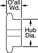
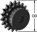
Machinable-Bore Sprockets for ANSI Roller Chain
For a custom fit on your shaft, these sprockets can be machined to your exact specifications. They come machined to the shaft diameter size listed and are machinable up to the maximum shaft diameter size.
![]() For technical drawings and 3-D models, click on a part number.
For technical drawings and 3-D models, click on a part number.
| Number of Teeth | For Shaft Dia. | For Max. Shaft Dia. | OD | Overall Wd. | Hub Dia. | Material | Each | |
For ANSI 35 Roller Chain (3/8" Pitch) | ||||||||
|---|---|---|---|---|---|---|---|---|
| 35 | 5/8" | 1 1/2" | 4.39" | 7/8" | 2 1/4" | Steel | 00000000 | 000000 |
| 40 | 5/8" | 1 1/2" | 4.99" | 1" | 2 1/4" | Steel | 00000000 | 00000 |
| 45 | 5/8" | 1 1/2" | 5.59" | 1" | 2 1/4" | Steel | 00000000 | 00000 |
| 60 | 3/4" | 1 1/2" | 7.38" | 1" | 2 1/4" | Steel | 00000000 | 00000 |
For ANSI 80 Roller Chain (1" Pitch) | ||||||||
| 9 | 1" | 1 5/16" | 3.35" | 1 5/8" | 2 1/4" | Steel | 0000000 | 00000 |
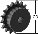
Wear-Resistant Sprockets for ANSI Roller Chain
Hardened teeth give these steel sprockets increased wear resistance for a long service life. Mount them onto your shaft and secure with a set screw—no machining necessary.
![]() For technical drawings and 3-D models, click on a part number.
For technical drawings and 3-D models, click on a part number.
Keyway | ||||||||||
|---|---|---|---|---|---|---|---|---|---|---|
| Number of Teeth | For Shaft Dia. | OD | Overall Wd. | Hub Dia. | Wd. | Dp. | Material | Includes | Each | |
| 9 | 1" | 3.35" | 1 5/8" | 2 1/4" | 1/4" | 1/8" | Steel | Two Set Screws | 00000000 | 000000 |
| 9 | 1 1/8" | 3.35" | 1 5/8" | 2 1/4" | 1/4" | 1/8" | Steel | Two Set Screws | 00000000 | 00000 |
| 9 | 1 3/16" | 3.35" | 1 5/8" | 2 1/4" | 1/4" | 1/8" | Steel | Two Set Screws | 00000000 | 00000 |
| 9 | 1 1/4" | 3.35" | 1 5/8" | 2 1/4" | 1/4" | 1/8" | Steel | Two Set Screws | 00000000 | 00000 |
Sprockets for Double-Strand ANSI Roller Chain
These sprockets come machined to the shaft diameter size listed and are machinable up to the maximum shaft diameter size. All have hardened teeth for increased wear resistance and a long service life.
![]() For technical drawings and 3-D models, click on a part number.
For technical drawings and 3-D models, click on a part number.
| Number of Teeth | For Shaft Dia. | For Max. Shaft Dia. | OD | Overall Wd. | Hub Dia. | Material | Each | |
For ANSI 60-2 Roller Chain (3/4" Pitch) | ||||||||
|---|---|---|---|---|---|---|---|---|
| 13 | 1" | 1 1/2" | 3.49" | 2 1/8" | 2 1/4" | Steel | 0000000 | 0000000 |
Wear-Resistant Wide-Hub Idler Sprockets for ANSI Roller Chain
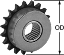
Hardened teeth give these steel sprockets increased wear resistance for a long service life. The wide hub provides stability under heavy loads. Designed to rotate freely on built-in bearings, idler sprockets maintain constant tension on your drive by pressing against your chain to take up slack and reduce wear and vibration. They are for use with roller chain tensioners.
![]() For technical drawings and 3-D models, click on a part number.
For technical drawings and 3-D models, click on a part number.
Bearing | |||||||||
|---|---|---|---|---|---|---|---|---|---|
| Number of Teeth | For Shaft Dia. | OD | Overall Wd. | Hub Dia. | Material | Type | Material | Each | |
For ANSI 50 Roller Chain (5/8" Pitch) | |||||||||
| 17 | 1" | 3.72" | 1" | 2 1/4" | Steel | Needle Roller | Bronze | 0000000 | 0000000 |
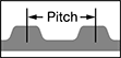
L Series Corrosion-Resistant Timing Belt Pulleys
Pulleys are anodized aluminum, which is more corrosion resistant than steel. All are L series (light) and have trapezoidal teeth. Select a pulley with a maximum belt width that’s the same or larger than your timing belt width.
![]() For technical drawings and 3-D models, click on a part number.
For technical drawings and 3-D models, click on a part number.
| OD | Number of Teeth | Pitch | For Shaft Dia. | Bore Type | Inside Wd. | Outside Wd. | Overall Wd. | Pitch Dia. | Number of Flanges | Fabrication | Material | Hub Dia. | Each | |
For 1/2" Max. Belt Wd. | ||||||||||||||
|---|---|---|---|---|---|---|---|---|---|---|---|---|---|---|
| 3.094" | 24 | 0.375" | 1/2" | Finished | 0.55" | 0.719" | 1.375" | 2.865" | 2 | Machined | Anodized Aluminum | 2.25" | 0000000 | 000000 |
| 3.33" | 26 | 0.375" | 1/2" | Finished | 0.58" | 0.75" | 1.375" | 3.104" | 2 | Machined | Anodized Aluminum | 2.25" | 0000000 | 00000 |
| 3.566" | 28 | 0.375" | 1/2" | Finished | 0.58" | 0.75" | 1.375" | 3.342" | 2 | Machined | Anodized Aluminum | 2.25" | 0000000 | 00000 |
| 3.8" | 30 | 0.375" | 1/2" | Finished | 0.58" | 0.75" | 1.375" | 3.581" | 2 | Machined | Anodized Aluminum | 2.25" | 0000000 | 00000 |
For 3/4" Max. Belt Wd. | ||||||||||||||
| 3.094" | 24 | 0.375" | 1/2" | Finished | 0.83" | 1" | 1.5" | 2.865" | 2 | Machined | Anodized Aluminum | 2.25" | 0000000 | 00000 |
| 3.33" | 26 | 0.375" | 1/2" | Finished | 0.83" | 1" | 1.5" | 3.104" | 2 | Machined | Anodized Aluminum | 2.25" | 0000000 | 00000 |
| 3.566" | 28 | 0.375" | 1/2" | Finished | 0.83" | 1" | 1.5" | 3.342" | 2 | Machined | Anodized Aluminum | 2.25" | 0000000 | 00000 |
| 3.8" | 30 | 0.375" | 1/2" | Finished | 0.83" | 1" | 1.5" | 3.581" | 2 | Machined | Anodized Aluminum | 2.25" | 0000000 | 00000 |
For 1" Max. Belt Wd. | ||||||||||||||
| 3.094" | 24 | 0.375" | 1/2" | Finished | 1.08" | 1.25" | 1.75" | 2.865" | 2 | Machined | Anodized Aluminum | 2.25" | 0000000 | 00000 |
L Series Timing Belt Pulleys

Pulleys are L series (light) and have trapezoidal teeth. Select a pulley with a maximum belt width that’s the same or larger than your timing belt width.
![]() For technical drawings and 3-D models, click on a part number.
For technical drawings and 3-D models, click on a part number.
| OD | Number of Teeth | Pitch | For Shaft Dia. | Bore Type | Inside Wd. | Outside Wd. | Overall Wd. | Pitch Dia. | Number of Flanges | Fabrication | Material | Hub Dia. | Each | |
For 1/2" Max. Belt Wd. | ||||||||||||||
|---|---|---|---|---|---|---|---|---|---|---|---|---|---|---|
| 3.109" | 24 | 0.375" | 1/2" | Plain | 0.563" | 0.75" | 1.5" | 2.865" | 2 | Sintered | Steel | 2.25" | 0000000 | 000000 |
For 3/4" Max. Belt Wd. | ||||||||||||||
| 3.109" | 24 | 0.375" | 5/8" | Plain | 0.813" | 1" | 1.75" | 2.865" | 2 | Sintered | Steel | 2.25" | 00000000 | 00000 |
For 1" Max. Belt Wd. | ||||||||||||||
| 3.109" | 24 | 0.375" | 5/8" | Plain | 1.063" | 1.25" | 2" | 2.865" | 2 | Sintered | Steel | 2.25" | 00000000 | 00000 |
H Series Timing Belt Pulleys
Pulleys are H series (heavy) and have trapezoidal teeth. Select a pulley with a maximum belt width that’s the same or larger than your timing belt width.
![]() For technical drawings and 3-D models, click on a part number.
For technical drawings and 3-D models, click on a part number.

| OD | Number of Teeth | Pitch | For Shaft Dia. | Bore Type | Inside Wd. | Outside Wd. | Overall Wd. | Pitch Dia. | Number of Flanges | Fabrication | Material | Hub Dia. | Each | |
For 1" Max. Belt Wd. | ||||||||||||||
|---|---|---|---|---|---|---|---|---|---|---|---|---|---|---|
| 3.109" | 18 | 0.500" | 5/8" | Plain | 1.063" | 1.313" | 2" | 2.865" | 2 | Sintered | Steel | 2.25" | 0000000 | 000000 |
For 1 1/2" Max. Belt Wd. | ||||||||||||||
| 3.11" | 18 | 0.500" | 3/4" | Plain | 1.625" | 1.813" | 2.563" | 2.865" | 2 | Sintered | Steel | 2.25" | 0000000 | 000000 |
| 3.25" | 19 | 0.500" | 3/4" | Plain | 1.625" | 1.813" | 2.625" | 3.024" | 2 | Sintered | Steel | 2.25" | 0000000 | 000000 |
For 2" Max. Belt Wd. | ||||||||||||||
| 3.25" | 19 | 0.500" | 3/4" | Plain | 2.125" | 2.344" | 3.219" | 3.024" | 2 | Sintered | Steel | 2.25" | 00000000 | 000000 |
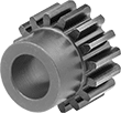
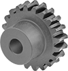
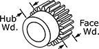
Metal Gears and Gear Racks—14 1/2° Pressure Angle
A former industry standard, 14½° pressure angle gears are often found on older machinery. Made of carbon steel, they have high strength and are better than plastic gears and gear racks for high-load, high-speed, and heavy duty applications.
Combine gears with different numbers of teeth to change speed and torque in your assembly. Combine a gear and rack to convert rotary motion into linear motion.
For components to mesh correctly, they must have the same pressure angle and pitch.
Gears with machinable bore have a large hub diameter so you can machine them to fit your shaft.
Gears with teeth that are not hardened can be hardened to fit your application. Hardening a gear's teeth increases its wear resistance.
![]() For technical drawings and 3-D models, click on a part number.
For technical drawings and 3-D models, click on a part number.
Hub | Keyway | ||||||||||||||
|---|---|---|---|---|---|---|---|---|---|---|---|---|---|---|---|
| Gear Pitch | Number of Teeth | Gear Pitch Dia. | OD | Face Wd. | Overall Wd. | For Shaft Dia. | Material | Teeth Heat Treatment | Dia. | Wd. | Wd. | Dp. | Set Screw Thread Size | Each | |
Round/Machinable Bore | |||||||||||||||
| 12 | 30 | 2 1/2" | 2.67" | 3/4" | 1.375" | 5/8"-1 5/16" | 1144 Carbon Steel | Not Hardened | 2.25" | 0.625" | __ | __ | __ | 0000000 | 000000 |
| 12 | 32 | 2.667" | 2.83" | 3/4" | 1.375" | 5/8"-1 5/16" | 1144 Carbon Steel | Not Hardened | 2.25" | 0.625" | __ | __ | __ | 0000000 | 00000 |
| 10 | 35 | 3 1/2" | 3.7" | 1" | 1.875" | 3/4"-1 5/16" | 1144 Carbon Steel | Not Hardened | 2.25" | 0.875" | __ | __ | __ | 000000 | 00000 |
| 10 | 40 | 4" | 4.2" | 1" | 1.875" | 7/8"-1 5/16" | 1144 Carbon Steel | Not Hardened | 2.25" | 0.875" | __ | __ | __ | 0000000 | 000000 |
Keyed Bore with Set Screw | |||||||||||||||
| 12 | 30 | 2 1/2" | 2.67" | 3/4" | 1.375" | 5/8" | 1144 Carbon Steel | Not Hardened | 2.25" | 0.625" | 0.188" | 0.094" | 1/4"-20 | 0000000 | 000000 |
| 12 | 32 | 2.667" | 2.83" | 3/4" | 1.375" | 5/8" | 1144 Carbon Steel | Not Hardened | 2.25" | 0.625" | 0.188" | 0.094" | 1/4"-20 | 0000000 | 000000 |
| 10 | 35 | 3 1/2" | 3.7" | 1" | 1.875" | 3/4" | 1144 Carbon Steel | Not Hardened | 2.25" | 0.875" | 0.188" | 0.094" | 1/4"-20 | 0000000 | 000000 |
Metal Worms and Worm Gears
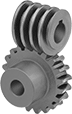
Worm gears use screw threads to make large reductions to shaft speed while transmitting motion at a right angle. They transmit motion from worm to gear and cannot be reversed. For gears and worms to mesh correctly, they must have the same pressure angle and pitch/module. These worms are compatible with plastic worm gears.
Speed ratio is the ratio by which output shaft speed is reduced. As speed decreases, torque increases.
Cast iron gears are strong and durable.
![]() For technical drawings and 3-D models, click on a part number.
For technical drawings and 3-D models, click on a part number.
Hub | |||||||||||||||||
|---|---|---|---|---|---|---|---|---|---|---|---|---|---|---|---|---|---|
| Gear Pitch | Speed Ratio | Number of Teeth | Pressure Angle | Gear Pitch Dia. | For Number of Thread Starts | OD | Face Wd. | Overall Wd. | For Shaft Dia. | Dia. | Wd. | Material | For Thread Direction | Teeth Heat Treatment | Teeth Fabrication | Each | |
Round Bore—Cast Iron | |||||||||||||||||
| 6 | 30:1 | 30 | 14 1/2° | 5" | 1 | 5.37" | 1" | 1.875" | 7/8" | 2.25" | 0.875" | Cast Iron | Right Hand | Not Hardened | Not Ground | 000000000 | 0000000 |
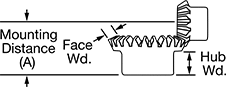
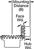
Metal Bevel Gears


A type of miter gear where one gear (sometimes called a pinion) is smaller than the other, bevel gears provide right-angle speed reduction at speed ratios ranging from 2:1 to 5:1. All are carbon steel for strength; they're compatible with plastic bevel gears. Teeth are not hardened so you can harden them to fit your application. Hardening a gear’s teeth increases its wear resistance.
A complete set consists of a gear and pinion (sold separately). For a gear and pinion to mesh correctly, they must have the same pressure angle, pitch/module, and face width. Speed ratio is the ratio by which shaft speed is reduced when transferring motion from pinion to gear. To increase shaft speed, transfer motion from gear to pinion. Changing shaft speed also changes torque: as speed decreases, torque increases.
![]() For technical drawings and 3-D models, click on a part number.
For technical drawings and 3-D models, click on a part number.
Hub | ||||||||||||||
|---|---|---|---|---|---|---|---|---|---|---|---|---|---|---|
| Face Wd. | Gear Pitch | Pressure Angle | Speed Ratio | Number of Teeth | Gear Pitch Dia. | OD | Overall Wd. | For Shaft Dia. | Mounting Distance (A) | Dia. | Wd. | Material | Each | |
Round Bore | ||||||||||||||
| 0.48" | 16 | 20° | 4:1 | 64 | 4" | 4.02" | 1.019" | 5/8" | 1.375" | 2.25" | 0.563" | 1144 Carbon Steel | 0000000 | 0000000 |

Hub | ||||||||||||||
|---|---|---|---|---|---|---|---|---|---|---|---|---|---|---|
| Face Wd. | Gear Pitch | Pressure Angle | Speed Ratio | Number of Teeth | Gear Pitch Dia. | OD | Overall Wd. | For Shaft Dia. | Mounting Distance (B) | Dia. | Wd. | Material | Each | |
Round Bore | ||||||||||||||
| 0.48" | 16 | 20° | 4:1 | 16 | 1" | 1.17" | 0.989" | 1/2" | 2.5" | 0.813" | 0.438" | 1144 Carbon Steel | 0000000 | 000000 |