Filter by
Number of Teeth
Shaft Diameter

OD
ID


Chain Type
Strand Type
Component

Width
Overall Width
Hub Diameter
Sprocket Type
RoHS
Export Control Classification Number (ECCN)
REACH
DFARS Specialty Metals
Shaft Mount Type

Sprockets
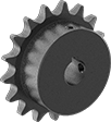 | 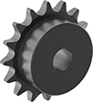 |
Finished Bore | Plain Bore |
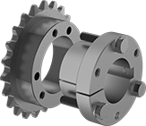
Sprocket teeth mesh with your roller chain to smoothly transmit power. These U.S.-made sprockets have machined teeth for a more precise fit than flame-cut or punched teeth, allowing them to glide in and out of the chain to reduce wear and extend chain life.
Steel—Steel is strong, but best for dry environments since moisture will cause it to rust.
Finished Bore—Mount these sprockets onto your shaft and secure with a set screw—no machining required.
Plain Bore—Plain bore sprockets give you options—machine a custom bore, weld, or press-fit them in place. They're sized to the minimum shaft diameter listed and are machinable up to the maximum.
For Roller Chain | Keyway | |||||||||||
|---|---|---|---|---|---|---|---|---|---|---|---|---|
Trade No. | Std. | Pitch | No. of Teeth | OD | Bore Type | For Shaft Dia. | Wd. | Dp. | Each | |||
For Single Strand | ||||||||||||
Steel | ||||||||||||
| 25 | ANSI | 1/4" | 45 | 3 3/4" | Finished | 1/2" | — | — | 2737T311 | 000000 | ||
| 25 | ANSI | 1/4" | 45 | 3 3/4" | Finished | 5/8" | 3/16" | 3/32" | 2737T312 | 00000 | ||
| 25 | ANSI | 1/4" | 45 | 3 3/4" | Finished | 3/4" | 3/16" | 3/32" | 2737T313 | 00000 | ||
| 25 | ANSI | 1/4" | 45 | 3 3/4" | Finished | 7/8" | 3/16" | 3/32" | 2737T314 | 00000 | ||
| 25 | ANSI | 1/4" | 45 | 3 3/4" | Finished | 1" | 1/4" | 1/8" | 2737T315 | 00000 | ||
| 25 | ANSI | 1/4" | 45 | 3 3/4" | Finished | 1 1/4" | 1/4" | 1/8" | 2737T316 | 00000 | ||
| 25 | ANSI | 1/4" | 45 | 3 3/4" | Finished | 1 3/8" | 5/16" | 5/32" | 2737T317 | 00000 | ||
| 25 | ANSI | 1/4" | 45 | 3 3/4" | Plain | 1/2" to 1 3/8" | — | — | 6793K22 | 00000 | ||
| 35 | ANSI | 3/8" | 45 | 5 9/16" | Finished | 3/4" | 3/16" | 3/32" | 6236K262 | 00000 | ||
| 35 | ANSI | 3/8" | 45 | 5 9/16" | Finished | 7/8" | 3/16" | 3/32" | 6236K265 | 00000 | ||
| 35 | ANSI | 3/8" | 45 | 5 9/16" | Finished | 1 1/8" | 1/4" | 1/8" | 6236K266 | 00000 | ||
| 35 | ANSI | 3/8" | 45 | 5 9/16" | Finished | 1 3/16" | 1/4" | 1/8" | 6236K267 | 00000 | ||
| 35 | ANSI | 3/8" | 45 | 5 9/16" | Finished | 1 1/4" | 1/4" | 1/8" | 6236K268 | 00000 | ||
| 35 | ANSI | 3/8" | 45 | 5 9/16" | Plain | 5/8" to 1 1/2" | — | — | 6793K138 | 00000 | ||
| 40 | ANSI | 1/2" | 45 | 7 7/16" | Finished | 5/8" | 3/16" | 3/32" | 6236K701 | 000000 | ||
| 40 | ANSI | 1/2" | 45 | 7 7/16" | Finished | 3/4" | 3/16" | 3/32" | 6236K365 | 000000 | ||
| 40 | ANSI | 1/2" | 45 | 7 7/16" | Finished | 7/8" | 3/16" | 3/32" | 6236K366 | 000000 | ||
| 40 | ANSI | 1/2" | 45 | 7 7/16" | Finished | 1" | 1/4" | 1/8" | 6236K361 | 000000 | ||
| 40 | ANSI | 1/2" | 45 | 7 7/16" | Finished | 1 1/8" | 1/4" | 1/8" | 6236K367 | 000000 | ||
| 40 | ANSI | 1/2" | 45 | 7 7/16" | Finished | 1 3/16" | 1/4" | 1/8" | 6236K368 | 000000 | ||
| 40 | ANSI | 1/2" | 45 | 7 7/16" | Finished | 1 1/4" | 1/4" | 1/8" | 6236K369 | 000000 | ||
| 40 | ANSI | 1/2" | 45 | 7 7/16" | Finished | 1 3/8" | 5/16" | 5/32" | 6236K838 | 000000 | ||
| 40 | ANSI | 1/2" | 45 | 7 7/16" | Finished | 1 7/16" | 3/8" | 3/16" | 6236K363 | 000000 | ||
| 40 | ANSI | 1/2" | 45 | 7 7/16" | Finished | 1 1/2" | 3/8" | 3/16" | 6236K771 | 000000 | ||
| 40 | ANSI | 1/2" | 45 | 7 7/16" | Plain | 3/4" to 2 3/8" | — | — | 6793K162 | 00000 | ||
| 41 | ANSI | 1/2" | 45 | 7 7/16" | Finished | 3/4" | 3/16" | 3/32" | 2737T682 | 000000 | ||
| 41 | ANSI | 1/2" | 45 | 7 7/16" | Finished | 1" | 1/4" | 1/8" | 2737T684 | 000000 | ||
| 41 | ANSI | 1/2" | 45 | 7 7/16" | Finished | 1 1/4" | 1/4" | 1/8" | 2737T685 | 000000 | ||
| 41 | ANSI | 1/2" | 45 | 7 7/16" | Finished | 1 1/2" | 3/8" | 3/16" | 2737T687 | 000000 | ||
| 50 | ANSI | 5/8" | 45 | 9 5/16" | Finished | 3/4" | 3/16" | 3/32" | 6236K467 | 000000 | ||
| 50 | ANSI | 5/8" | 45 | 9 5/16" | Finished | 7/8" | 3/16" | 3/32" | 6236K468 | 000000 | ||
| 50 | ANSI | 5/8" | 45 | 9 5/16" | Finished | 1" | 1/4" | 1/8" | 6236K461 | 000000 | ||
| 50 | ANSI | 5/8" | 45 | 9 5/16" | Finished | 1 1/8" | 1/4" | 1/8" | 6236K469 | 000000 | ||
| 50 | ANSI | 5/8" | 45 | 9 5/16" | Finished | 1 3/16" | 1/4" | 1/8" | 6236K466 | 000000 | ||
| 50 | ANSI | 5/8" | 45 | 9 5/16" | Finished | 1 1/4" | 1/4" | 1/8" | 6236K462 | 000000 | ||
| 50 | ANSI | 5/8" | 45 | 9 5/16" | Finished | 1 3/8" | 5/16" | 5/32" | 6236K746 | 000000 | ||
| 50 | ANSI | 5/8" | 45 | 9 5/16" | Finished | 1 7/16" | 3/8" | 3/16" | 6236K747 | 000000 | ||
| 50 | ANSI | 5/8" | 45 | 9 5/16" | Finished | 1 1/2" | 3/8" | 3/16" | 6236K748 | 000000 | ||
| 50 | ANSI | 5/8" | 45 | 9 5/16" | Finished | 1 5/8" | 3/8" | 3/16" | 6236K849 | 000000 | ||
| 50 | ANSI | 5/8" | 45 | 9 5/16" | Finished | 1 3/4" | 3/8" | 3/16" | 6236K749 | 000000 | ||
| 50 | ANSI | 5/8" | 45 | 9 5/16" | Finished | 1 15/16" | 1/2" | 1/4" | 6236K751 | 000000 | ||
| 50 | ANSI | 5/8" | 45 | 9 5/16" | Plain | 3/4" to 2 1/2" | — | — | 6793K185 | 000000 | ||
| 60 | ANSI | 3/4" | 45 | 11 3/16" | Finished | 1" | 1/4" | 1/8" | 6236K561 | 000000 | ||
| 60 | ANSI | 3/4" | 45 | 11 3/16" | Finished | 1 1/8" | 1/4" | 1/8" | 6236K568 | 000000 | ||
| 60 | ANSI | 3/4" | 45 | 11 3/16" | Finished | 1 3/16" | 1/4" | 1/8" | 6236K569 | 000000 | ||
| 60 | ANSI | 3/4" | 45 | 11 3/16" | Finished | 1 1/4" | 1/4" | 1/8" | 6236K703 | 000000 | ||
| 60 | ANSI | 3/4" | 45 | 11 3/16" | Finished | 1 3/8" | 5/16" | 5/32" | 6236K567 | 000000 | ||
| 60 | ANSI | 3/4" | 45 | 11 3/16" | Finished | 1 7/16" | 3/8" | 3/16" | 6236K704 | 000000 | ||
| 60 | ANSI | 3/4" | 45 | 11 3/16" | Finished | 1 1/2" | 3/8" | 3/16" | 6236K564 | 000000 | ||
| 60 | ANSI | 3/4" | 45 | 11 3/16" | Finished | 1 5/8" | 3/8" | 3/16" | 6236K705 | 000000 | ||
| 60 | ANSI | 3/4" | 45 | 11 3/16" | Finished | 1 3/4" | 3/8" | 3/16" | 6236K706 | 000000 | ||
| 60 | ANSI | 3/4" | 45 | 11 3/16" | Finished | 1 15/16" | 1/2" | 1/4" | 6236K707 | 000000 | ||
| 60 | ANSI | 3/4" | 45 | 11 3/16" | Finished | 2" | 1/2" | 1/4" | 6236K708 | 000000 | ||
| 60 | ANSI | 3/4" | 45 | 11 3/16" | Finished | 2 3/16" | 1/2" | 1/4" | 6236K709 | 000000 | ||
| 60 | ANSI | 3/4" | 45 | 11 3/16" | Finished | 2 7/16" | 5/8" | 5/16" | 6236K711 | 000000 | ||
| 06B | ISO | 3/8" | 45 | 142 mm | Plain | 16 mm to 45 mm | — | — | 2302K207 | 00000 | ||
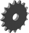
Flat Sprockets
 |
For Roller Chain | ||||||||||
|---|---|---|---|---|---|---|---|---|---|---|
Trade No. | Std. | Pitch | No. of Teeth | OD | Bore Type | For Shaft Dia. | Each | |||
For Single Strand | ||||||||||
Steel | ||||||||||
| 35 | ANSI | 3/8" | 45 | 5 9/16" | Plain | 19/32" to 4 61/64" | 2299K319 | 000000 | ||
| 40 | ANSI | 1/2" | 45 | 7 7/16" | Plain | 23/32" to 6 39/64" | 2299K37 | 00000 | ||
| 50 | ANSI | 5/8" | 45 | 9 5/16" | Plain | 23/32" to 8 9/32" | 2299K58 | 00000 | ||
| 60 | ANSI | 3/4" | 45 | 11 3/16" | Plain | 15/16" to 9 15/16" | 2299K82 | 00000 | ||
| 80 | ANSI | 1" | 45 | 14 7/8" | Plain | 1 1/4" to 13 9/32" | 2299K106 | 000000 | ||
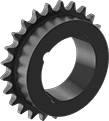
Quick-Disconnect (QD) Bushing-Bore Sprockets
 | 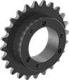 |
Sprocket Shown with Bushing (Sold Separately) | For Single Strand |
For Roller Chain | |||||||||
|---|---|---|---|---|---|---|---|---|---|
Trade No. | Std. | Pitch | No. of Teeth | OD | For Bushing Trade No. | Each | |||
For Single Strand | |||||||||
Steel | |||||||||
| 35 | ANSI | 3/8" | 45 | 5 9/16" | SH | 62375K21 | 000000 | ||
| 40 | ANSI | 1/2" | 45 | 7 7/16" | SDS | 62375K65 | 000000 | ||
| 50 | ANSI | 5/8" | 45 | 9 5/16" | SDS | 62375K85 | 000000 | ||
| 60 | ANSI | 3/4" | 45 | 11 3/16" | SF | 62375K105 | 000000 | ||
 |
Quick-Disconnect Bushing |
Bushing Trade No. | For Shaft Dia. | Each | |||
|---|---|---|---|---|---|
Quick-Disconnect Bushing | |||||
| SH | 1/2" | 6086K211 | 000000 | ||
| SH | 5/8" | 6086K212 | 00000 | ||
| SH | 11/16" | 6086K226 | 00000 | ||
| SH | 3/4" | 6086K213 | 00000 | ||
| SH | 7/8" | 6086K214 | 00000 | ||
| SH | 15/16" | 6086K215 | 00000 | ||
| SH | 1" | 6086K216 | 00000 | ||
| SH | 1 1/16" | 6086K217 | 00000 | ||
| SH | 1 1/8" | 6086K218 | 00000 | ||
| SH | 1 3/16" | 6086K219 | 00000 | ||
| SH | 1 1/4" | 6086K221 | 00000 | ||
| SH | 1 5/16" | 6086K848 | 00000 | ||
| SH | 1 3/8" | 6086K222 | 00000 | ||
| SH | 1 7/16" | 6086K849 | 00000 | ||
| SH | 1 1/2" | 6086K223 | 00000 | ||
| SH | 1 5/8" | 6086K224 | 00000 | ||
| SH | 1 11/16" | 6086K225 | 00000 | ||
| SH | 22 mm | 2344K71 | 00000 | ||
| SH | 24 mm | 2344K11 | 00000 | ||
| SH | 25 mm | 2344K12 | 00000 | ||
| SH | 28 mm | 2344K13 | 00000 | ||
| SH | 30 mm | 2344K14 | 00000 | ||
| SH | 32 mm | 2344K15 | 00000 | ||
| SH | 35 mm | 2344K16 | 00000 | ||
| SDS | 1/2" | 6086K311 | 00000 | ||
| SDS | 9/16" | 6086K131 | 00000 | ||
| SDS | 5/8" | 6086K312 | 00000 | ||
| SDS | 3/4" | 6086K313 | 00000 | ||
| SDS | 7/8" | 6086K314 | 00000 | ||
| SDS | 15/16" | 6086K315 | 00000 | ||
| SDS | 1" | 6086K316 | 00000 | ||
| SDS | 1 1/16" | 6086K317 | 00000 | ||
| SDS | 1 1/8" | 6086K318 | 00000 | ||
| SDS | 1 3/16" | 6086K319 | 00000 | ||
| SDS | 1 1/4" | 6086K321 | 00000 | ||
| SDS | 1 5/16" | 6086K851 | 00000 | ||
| SDS | 1 3/8" | 6086K322 | 00000 | ||
| SDS | 1 7/16" | 6086K323 | 00000 | ||
| SDS | 1 1/2" | 6086K324 | 00000 | ||
| SDS | 1 9/16" | 6086K132 | 00000 | ||
| SDS | 1 5/8" | 6086K325 | 00000 | ||
| SDS | 1 11/16" | 6086K852 | 00000 | ||
| SDS | 1 3/4" | 6086K326 | 00000 | ||
| SDS | 1 7/8" | 6086K853 | 00000 | ||
| SDS | 1 15/16" | 6086K854 | 00000 | ||
| SDS | 2" | 6086K327 | 00000 | ||
| SDS | 24 mm | 2344K21 | 00000 | ||
| SDS | 25 mm | 2344K22 | 00000 | ||
| SDS | 28 mm | 2344K23 | 00000 | ||
| SDS | 30 mm | 2344K24 | 00000 | ||
| SDS | 32 mm | 2344K25 | 00000 | ||
| SDS | 35 mm | 2344K26 | 00000 | ||
| SDS | 38 mm | 2344K27 | 00000 | ||
| SDS | 40 mm | 2344K28 | 00000 | ||
| SDS | 42 mm | 2344K29 | 00000 | ||
| SF | 1/2" | 6086K614 | 00000 | ||
| SF | 5/8" | 6086K615 | 00000 | ||
| SF | 3/4" | 6086K616 | 00000 | ||
| SF | 7/8" | 6086K617 | 00000 | ||
| SF | 1" | 6086K619 | 00000 | ||
| SF | 1 1/8" | 6086K622 | 00000 | ||
| SF | 1 3/16" | 6086K623 | 00000 | ||
| SF | 1 1/4" | 6086K624 | 00000 | ||
| SF | 1 3/8" | 6086K625 | 00000 | ||
| SF | 1 7/16" | 6086K626 | 00000 | ||
| SF | 1 1/2" | 6086K627 | 00000 | ||
| SF | 1 5/8" | 6086K628 | 00000 | ||
| SF | 1 11/16" | 6086K629 | 00000 | ||
| SF | 1 3/4" | 6086K631 | 00000 | ||
| SF | 1 7/8" | 6086K632 | 00000 | ||
| SF | 1 15/16" | 6086K633 | 00000 | ||
| SF | 2" | 6086K634 | 00000 | ||
| SF | 2 1/8" | 6086K635 | 00000 | ||
| SF | 2 3/16" | 6086K636 | 00000 | ||
| SF | 2 1/4" | 6086K637 | 00000 | ||
| SF | 2 3/8" | 6086K864 | 00000 | ||
| SF | 2 7/16" | 6086K865 | 00000 | ||
| SF | 2 1/2" | 6086K638 | 00000 | ||
| SF | 2 5/8" | 6086K866 | 00000 | ||
| SF | 2 3/4" | 6086K867 | 00000 | ||
| SF | 2 15/16" | 6086K639 | 00000 | ||
| SF | 30 mm | 2344K75 | 00000 | ||
| SF | 35 mm | 2344K62 | 00000 | ||
| SF | 40 mm | 2344K64 | 00000 | ||
| SF | 50 mm | 2344K67 | 00000 | ||
| SF | 55 mm | 2344K68 | 00000 | ||
| SF | 60 mm | 2344K69 | 00000 | ||
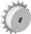
Plastic Sprockets
Taper-Lock Bushing-Bore Sprockets
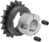 |  |
Sprocket Shown with Bushing (Sold Separately) | For Single Strand |
For Roller Chain | |||||||||
|---|---|---|---|---|---|---|---|---|---|
Trade No. | Std. | Pitch | No. of Teeth | OD | For Bushing Trade No. | Each | |||
For Single Strand | |||||||||
Steel | |||||||||
| 35 | ANSI | 3/8" | 45 | 5 9/16" | 1610 | 2590K26 | 0000000 | ||
| 40 | ANSI | 1/2" | 45 | 7 7/16" | 1610 | 2590K49 | 000000 | ||
| 50 | ANSI | 5/8" | 45 | 9 5/16" | 2012 | 2590K74 | 000000 | ||
| 60 | ANSI | 3/4" | 45 | 11 3/16" | 2012 | 2590K102 | 000000 | ||
 |
Taper-Lock Bushing |
Bushing Trade No. | For Shaft Dia. | Each | |||
|---|---|---|---|---|---|
Taper-Lock Bushing | |||||
| 1610 | 1/2" | 57095K169 | 000000 | ||
| 1610 | 5/8" | 57095K161 | 00000 | ||
| 1610 | 3/4" | 57095K162 | 00000 | ||
| 1610 | 13/16" | 57095K487 | 00000 | ||
| 1610 | 7/8" | 57095K159 | 00000 | ||
| 1610 | 15/16" | 57095K489 | 00000 | ||
| 1610 | 1" | 57095K163 | 00000 | ||
| 1610 | 1 1/16" | 57095K484 | 00000 | ||
| 1610 | 1 1/8" | 57095K164 | 00000 | ||
| 1610 | 1 3/16" | 57095K311 | 00000 | ||
| 1610 | 1 1/4" | 57095K165 | 00000 | ||
| 1610 | 1 5/16" | 57095K485 | 00000 | ||
| 1610 | 1 3/8" | 57095K166 | 00000 | ||
| 1610 | 1 7/16" | 57095K312 | 00000 | ||
| 1610 | 1 1/2" | 57095K167 | 00000 | ||
| 1610 | 1 9/16" | 57095K486 | 00000 | ||
| 1610 | 1 5/8" | 57095K168 | 00000 | ||
| 1610 | 1 11/16" | 57095K271 | 00000 | ||
| 1610 | 14 mm | 57095K488 | 00000 | ||
| 1610 | 16 mm | 57095K491 | 00000 | ||
| 1610 | 18 mm | 57095K492 | 00000 | ||
| 1610 | 19 mm | 57095K493 | 00000 | ||
| 1610 | 20 mm | 57095K494 | 00000 | ||
| 1610 | 22 mm | 57095K495 | 00000 | ||
| 1610 | 24 mm | 57095K496 | 00000 | ||
| 1610 | 25 mm | 57095K497 | 00000 | ||
| 1610 | 28 mm | 57095K498 | 00000 | ||
| 1610 | 30 mm | 57095K499 | 00000 | ||
| 1610 | 32 mm | 57095K511 | 00000 | ||
| 1610 | 35 mm | 57095K512 | 00000 | ||
| 1610 | 38 mm | 57095K513 | 00000 | ||
| 2012 | 1/2" | 57095K181 | 00000 | ||
| 2012 | 5/8" | 57095K294 | 00000 | ||
| 2012 | 3/4" | 57095K182 | 00000 | ||
| 2012 | 7/8" | 57095K295 | 00000 | ||
| 2012 | 15/16" | 57095K545 | 00000 | ||
| 2012 | 1" | 57095K183 | 00000 | ||
| 2012 | 1 1/8" | 57095K184 | 00000 | ||
| 2012 | 1 3/16" | 57095K199 | 00000 | ||
| 2012 | 1 1/4" | 57095K185 | 00000 | ||
| 2012 | 1 3/8" | 57095K186 | 00000 | ||
| 2012 | 1 7/16" | 57095K187 | 00000 | ||
| 2012 | 1 1/2" | 57095K188 | 00000 | ||
| 2012 | 1 9/16" | 57095K542 | 00000 | ||
| 2012 | 1 5/8" | 57095K189 | 00000 | ||
| 2012 | 1 11/16" | 57095K538 | 00000 | ||
| 2012 | 1 3/4" | 57095K191 | 00000 | ||
| 2012 | 1 7/8" | 57095K192 | 00000 | ||
| 2012 | 1 15/16" | 57095K313 | 00000 | ||
| 2012 | 2" | 57095K193 | 00000 | ||
| 2012 | 2 1/8" | 57095K196 | 000000 | ||
| 2012 | 20 mm | 57095K548 | 00000 | ||
| 2012 | 22 mm | 57095K549 | 00000 | ||
| 2012 | 24 mm | 57095K551 | 00000 | ||
| 2012 | 25 mm | 57095K552 | 00000 | ||
| 2012 | 28 mm | 57095K553 | 00000 | ||
| 2012 | 30 mm | 57095K554 | 00000 | ||
| 2012 | 32 mm | 57095K555 | 00000 | ||
| 2012 | 35 mm | 57095K556 | 00000 | ||
| 2012 | 38 mm | 57095K557 | 00000 | ||
| 2012 | 40 mm | 57095K558 | 00000 | ||
| 2012 | 42 mm | 57095K559 | 00000 | ||
| 2012 | 45 mm | 57095K561 | 00000 | ||
| 2012 | 50 mm | 57095K563 | 00000 | ||
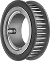
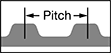
Ultra-High-Torque GT Timing Belt Pulleys
 |
 |
Pair these pulleys with the strongest timing belts we offer, Ultra-High-Torque GT Timing Belts. They can handle as much torque as roller chain. Their curved teeth fit snugly with matching belts for minimal play (backlash), so these pulleys are good for applications that require precise positioning. All are compatible with Gates Poly Chain GT timing belts.
Iron—Strong but best for dry environments since moisture will cause them to rust.
Bushing Bore—Quickly swap or service parts in tight spaces—no press-fitting or special tools required. Mount a bushing (sold separately) on your shaft and slide the pulley over it. As you tighten the included set screws, the bushing grips the shaft and draws it into the pulley, creating a final hold that is more secure than with set screws alone.
For Bushing | |||||||||||
|---|---|---|---|---|---|---|---|---|---|---|---|
For Max. Belt Wd., mm | Pitch, mm | No. of Teeth | Bore Type | Type | Trade No. | Pitch Dia., mm | No. of Flanges | Each | |||
For 8MGT Trade Size | |||||||||||
Iron | |||||||||||
| 12 | 8 | 45 | Bushing | Taper Lock | 2012 | 115 | 2 | 7970K13 | 0000000 | ||
| 21 | 8 | 45 | Bushing | Taper Lock | 2012 | 115 | 2 | 7970K17 | 000000 | ||
| 36 | 8 | 45 | Bushing | Taper Lock | 2012 | 114.6 | 2 | 7970K103 | 000000 | ||
 |
Taper-Lock Bushing |
Bushing | |||||
|---|---|---|---|---|---|
Type | Trade No. | For Shaft Dia. | Each | ||
| Taper Lock | 2012 | 1/2" | 57095K181 | 000000 | |
| Taper Lock | 2012 | 5/8" | 57095K294 | 00000 | |
| Taper Lock | 2012 | 3/4" | 57095K182 | 00000 | |
| Taper Lock | 2012 | 7/8" | 57095K295 | 00000 | |
| Taper Lock | 2012 | 15/16" | 57095K545 | 00000 | |
| Taper Lock | 2012 | 1" | 57095K183 | 00000 | |
| Taper Lock | 2012 | 1 1/8" | 57095K184 | 00000 | |
| Taper Lock | 2012 | 1 3/16" | 57095K199 | 00000 | |
| Taper Lock | 2012 | 1 1/4" | 57095K185 | 00000 | |
| Taper Lock | 2012 | 1 3/8" | 57095K186 | 00000 | |
| Taper Lock | 2012 | 1 7/16" | 57095K187 | 00000 | |
| Taper Lock | 2012 | 1 1/2" | 57095K188 | 00000 | |
| Taper Lock | 2012 | 1 9/16" | 57095K542 | 00000 | |
| Taper Lock | 2012 | 1 5/8" | 57095K189 | 00000 | |
| Taper Lock | 2012 | 1 11/16" | 57095K538 | 00000 | |
| Taper Lock | 2012 | 1 3/4" | 57095K191 | 00000 | |
| Taper Lock | 2012 | 1 7/8" | 57095K192 | 00000 | |
| Taper Lock | 2012 | 1 15/16" | 57095K313 | 00000 | |
| Taper Lock | 2012 | 2" | 57095K193 | 00000 | |
| Taper Lock | 2012 | 2 1/8" | 57095K196 | 000000 | |
| Taper Lock | 2012 | 20 mm | 57095K548 | 00000 | |
| Taper Lock | 2012 | 22 mm | 57095K549 | 00000 | |
| Taper Lock | 2012 | 24 mm | 57095K551 | 00000 | |
| Taper Lock | 2012 | 25 mm | 57095K552 | 00000 | |
| Taper Lock | 2012 | 28 mm | 57095K553 | 00000 | |
| Taper Lock | 2012 | 30 mm | 57095K554 | 00000 | |
| Taper Lock | 2012 | 32 mm | 57095K555 | 00000 | |
| Taper Lock | 2012 | 35 mm | 57095K556 | 00000 | |
| Taper Lock | 2012 | 38 mm | 57095K557 | 00000 | |
| Taper Lock | 2012 | 40 mm | 57095K558 | 00000 | |
| Taper Lock | 2012 | 42 mm | 57095K559 | 00000 | |
| Taper Lock | 2012 | 45 mm | 57095K561 | 00000 | |
| Taper Lock | 2012 | 50 mm | 57095K563 | 00000 | |
Metal Bevel Gears


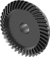
High-Load Metal Spiral Bevel Gears
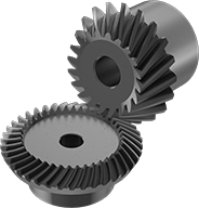 |
Gears Sold Separately |
 |
Large Gears |
The spiral teeth on these bevel gears stay in contact longer than straight teeth, so they can handle heavier loads at higher speeds. Use them to transmit motion at a right angle while changing shaft speed and torque. Their teeth engage gradually, which reduces vibration and noise, and they’re hardened for extra wear resistance. All are carbon steel for good strength. They have a machinable bore, so you can customize the size within the For Shaft Diameter range listed.
A complete set consists of a large gear and a small gear, also known as a pinion (sold separately). For the gears to mesh correctly, they must have the same face width, pitch or module, and pressure angle.
Speed Ratio—The ratio by which shaft speed is reduced when transferring motion from the smaller to the larger gear. To increase shaft speed, transfer motion from the larger to the smaller gear. Changing shaft speed also changes torque: as speed decreases, torque increases. To achieve the speed ratio listed, match it across a set of compatible gears.
Large Gears | ||||||||
|---|---|---|---|---|---|---|---|---|
Face Wd., mm | Gear Module | Pressure Angle | Speed Ratio | Material | For Shaft Dia., mm | Each | ||
| 15 | 2 | 20° | 3:1 | 1045 Carbon Steel | 12 to 30 | 6010N38 | 0000000 | |
Metal Spur Gears
Gears
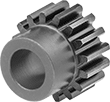 |  |
20° Pressure Angle Round Bore | Gear with Round Bore and Set Screw |
20° Pressure Angle—The current industry standard, these 20° pressure angle spur gears have thicker, stronger teeth than 14½° pressure angle gears.
Steel—Steel gears have hard, strong, and wear-resistant teeth, although they will rust when exposed to moisture and corrosive chemicals.
Hub, mm | ||||||||||||||
|---|---|---|---|---|---|---|---|---|---|---|---|---|---|---|
Gear Module | No. of Teeth | Gear Pitch Dia., mm | OD, mm | Face Wd., mm | Dia. | Wd. | Bore Type | For Shaft Dia., mm | Tooth Heat Treatment | Material | Each | |||
20° Pressure Angle | ||||||||||||||
Steel | ||||||||||||||
| 0.5 | 45 | 22.5 | 23.5 | 5 | 20 | 7 | Round Bore with Set Screw | 5 | Not Hardened | Black-Oxide 1045 Carbon Steel | 2664N324 | 000000 | ||
| 0.8 | 45 | 36 | 37.6 | 8 | 28 | 8 | Round Bore with Set Screw | 6 | Not Hardened | Black-Oxide 1045 Carbon Steel | 2664N342 | 00000 | ||
| 1 | 45 | 45 | 47 | 10 | 35 | 10 | Round Bore with Set Screw | 8 | Not Hardened | Black-Oxide 1045 Carbon Steel | 2664N14 | 00000 | ||
| 1 | 45 | 45 | 47 | 10 | 35 | 10 | Round Bore with Set Screw | 8 | Not Hardened | Black-Oxide 1045 Carbon Steel | 2664N366 | 00000 | ||
| 2 | 45 | 90 | 94 | 20 | 55 | 10 | Round Bore | 15 | Not Hardened | Black-Oxide 1045 Carbon Steel | 2664N403 | 00000 | ||
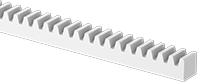
Gear Racks
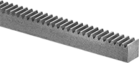 | 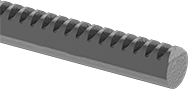 |
20° Pressure Angle—Rectangular | 20° Pressure Angle—Round |
These racks match with spur gears to convert rotary motion to linear motion. For components to mesh correctly, they must have the same pressure angle and pitch/module.
Steel—Steel gear racks have strong and wear-resistant teeth, although they will rust when exposed to moisture and corrosive chemicals.
Gear Module | Lg., mm | Pitch Ht., mm | Ht., mm | Face Wd., mm | Dia., mm | Tooth Heat Treatment | Material | Features | Each | |||
|---|---|---|---|---|---|---|---|---|---|---|---|---|
20° Pressure Angle—Rectangular | ||||||||||||
Steel | ||||||||||||
| 0.5 | 100 | 11.5 | 12 | 5 | — | Not Hardened | Black-Oxide 1045 Carbon Steel | — | 2485N242 | 000000 | ||
| 0.5 | 300 | 11.5 | 12 | 5 | — | Not Hardened | Black-Oxide 1045 Carbon Steel | Machined Ends | 2485N241 | 00000 | ||
| 0.8 | 100 | 11.5 | 12.3 | 8 | — | Not Hardened | Black-Oxide 1045 Carbon Steel | — | 2485N214 | 00000 | ||
| 1 | 100 | 11 | 12 | 10 | — | Not Hardened | Black-Oxide 1045 Carbon Steel | — | 2485N217 | 00000 | ||
| 1 | 300 | 11 | 12 | 10 | — | Not Hardened | Black-Oxide 1045 Carbon Steel | — | 2485N218 | 00000 | ||
| 1 | 500 | 8.8 | 9.8 | 10 | — | Not Hardened | 1045 Carbon Steel | — | 2485N201 | 00000 | ||
| 1 | 1,000 | 8.8 | 9.8 | 10 | — | Not Hardened | 1045 Carbon Steel | — | 2485N202 | 000000 | ||
| 2 | 100 | 23 | 25 | 20 | — | Not Hardened | Black-Oxide 1045 Carbon Steel | — | 2485N219 | 00000 | ||
| 2 | 300 | 23 | 25 | 20 | — | Not Hardened | Black-Oxide 1045 Carbon Steel | — | 2485N221 | 00000 | ||
| 2 | 500 | 17.8 | 19.8 | 20 | — | Not Hardened | 1045 Carbon Steel | — | 2485N205 | 000000 | ||
| 2 | 1,000 | 17.8 | 19.8 | 20 | — | Not Hardened | 1045 Carbon Steel | — | 2485N206 | 000000 | ||
| 2 | 1,000 | 18 | 20 | 20 | — | Not Hardened | Black-Oxide 1045 Carbon Steel | Machined Ends | 2485N224 | 000000 | ||
20° Pressure Angle—Round | ||||||||||||
Steel | ||||||||||||
| 1 | 500 | 9 | — | — | 10 | Not Hardened | Black-Oxide 1045 Carbon Steel | — | 2485N226 | 000000 | ||
| 2 | 1,000 | 18 | — | — | 20 | Not Hardened | Black-Oxide 1045 Carbon Steel | — | 2485N227 | 000000 | ||
Internal Gears
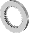 |
Save space without losing power. Insert a standard spur gear inside one of these gears for a compact assembly that smoothly transmits motion. Combine gears with different numbers of teeth to change speed and torque in your assembly. For components to mesh correctly, they must have the same pressure angle and pitch/module.
Steel—Steel gears have strong and wear-resistant teeth, although they will rust when exposed to moisture and corrosive chemicals.
Gear Module | No. of Teeth | Gear Pitch Dia., mm | OD, mm | ID, mm | Face Wd., mm | Tooth Heat Treatment | Finished Material | Each | |||
|---|---|---|---|---|---|---|---|---|---|---|---|
20° Pressure Angle | |||||||||||
Steel | |||||||||||
| 0.5 | 60 | 30 | 50 | 29 | 5 | Not Hardened | Black-Oxide 1045 Carbon Steel | 2696N16 | 000000 | ||
| 0.5 | 100 | 50 | 70 | 49 | 5 | Not Hardened | Black-Oxide 1045 Carbon Steel | 2696N15 | 00000 | ||
| 1 | 60 | 60 | 90 | 58 | 10 | Not Hardened | Black-Oxide 1045 Carbon Steel | 2696N27 | 00000 | ||
| 1 | 100 | 100 | 130 | 98 | 10 | Not Hardened | Black-Oxide 1045 Carbon Steel | 2696N26 | 000000 | ||
| 2 | 100 | 200 | 250 | 196 | 20 | Not Hardened | Black-Oxide 1045 Carbon Steel | 2696N33 | 000000 | ||
Precision High-Torque GT Timing Belt Pulleys
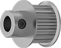 |
Finished Bore |
|
When precise synchronization is crucial, these pulleys minimize play (backlash). They’re often found in 3D printers, where accurate positioning is essential. Their curved teeth fit snugly with matching belts. Compared to pulleys with standard trapezoidal teeth, these pulleys transmit about three times more torque and run at higher speeds. All are compatible with Gates PowerGrip GT, 2GT, GT2, GT3, and GT4 series.
Corrosion-Resistant Aluminum—Won't rust in wet environments and one-third the weight of steel and iron. However, aluminum pulleys are not as strong as iron and steel.
Finished Bore—Mount these pulleys onto the shaft and secure with a set screw—no machining required.
For Max. Belt Wd., mm | Pitch, mm | No. of Teeth | Bore Type | For Shaft Dia. | Pitch Dia., mm | No. of Flanges | Hub Type | Each | |||
|---|---|---|---|---|---|---|---|---|---|---|---|
For 3MGT Trade Size | |||||||||||
Corrosion-Resistant Aluminum | |||||||||||
| 9 | 3 | 45 | Finished | 1/4" | 43 | 2 | Standard | 3764N141 | 000000 | ||
Timing Belt Pulleys
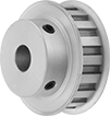 |
Finished Bore |
 |
For Max. Belt Wd. | Pitch | No. of Teeth | Bore Type | For Shaft Dia. | Pitch Dia. | Hub Type | Each | |||
|---|---|---|---|---|---|---|---|---|---|---|
For XL Trade Size | ||||||||||
Corrosion-Resistant Aluminum | ||||||||||
| 3/8" | 0.200" | 45 | Finished | 3/8" | 2.865" | Standard | 1277N29 | 000000 | ||
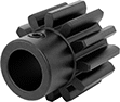
Plastic Spur Gears
Gears
 |
20° Pressure Angle |
20° Pressure Angle—The current industry standard, these 20° pressure angle spur gears have thicker, stronger teeth than 14½° pressure angle gears.
Acetal—Acetal gears absorb less water than nylon gears, so they’re less likely to swell.