


About Gears
More
About Roller Chain and Sprockets
More
Sprockets for Metric Roller Chain
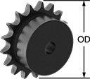
Designed to meet ISO 606 and DIN 8187 international dimensional standards, these sprockets are for use with compatible ISO and DIN roller chain. They come machined to the shaft diameter size listed and are machinable up to the maximum shaft diameter size.
![]() For technical drawings and 3-D models, click on a part number.
For technical drawings and 3-D models, click on a part number.
| Number of Teeth | For Shaft Dia., mm | For Max. Shaft Dia., mm | OD, mm | Overall Wd., mm | Hub Dia., mm | Material | Specifications Met | Each | |
For ISO 06B Roller Chain (9.53 mm Pitch) | |||||||||
|---|---|---|---|---|---|---|---|---|---|
| 26 | 12 | 38 | 83 | 28 | 60 | Steel | DIN 8187, ISO 606 | 0000000 | 000000 |
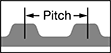
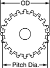
XL Series Lightweight Timing Belt Pulleys
Acetal and aluminum construction makes these pulleys useful in weight-sensitive applications. All are XL series (extra light) and have trapezoidal teeth. Select a pulley with a maximum belt width that’s the same or larger than your timing belt width.
![]() For technical drawings and 3-D models, click on a part number.
For technical drawings and 3-D models, click on a part number.

Hub | |||||||||||||||
|---|---|---|---|---|---|---|---|---|---|---|---|---|---|---|---|
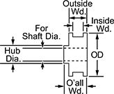
| OD | Number of Teeth | Pitch | For Shaft Dia. | Bore Type | Inside Wd. | Outside Wd. | Overall Wd. | Pitch Dia. | Number of Flanges | Fabrication | Material | Material | Dia. | Each | |
For 3/8" Max. Belt Wd. | |||||||||||||||
Metric | |||||||||||||||
| 83mm | 48 | 5.000mm | 12mm | Finished | 13mm | 16mm | 22mm | 77.62mm | 2 | Molded | Acetal | Aluminum | 22mm | 0000000 | 000000 |
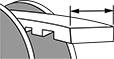
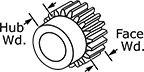
Metal Worms and Worm Gears
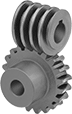
Worm gears use screw threads to make large reductions to shaft speed while transmitting motion at a right angle. They transmit motion from worm to gear and cannot be reversed. For gears and worms to mesh correctly, they must have the same pressure angle and pitch/module. These worms are compatible with plastic worm gears.
Speed ratio is the ratio by which output shaft speed is reduced. As speed decreases, torque increases.
Cast iron gears are strong and durable.
![]() For technical drawings and 3-D models, click on a part number.
For technical drawings and 3-D models, click on a part number.
Hub | |||||||||||||||||
|---|---|---|---|---|---|---|---|---|---|---|---|---|---|---|---|---|---|
| Module | Speed Ratio | Number of Teeth | Pressure Angle | Gear Pitch Dia., mm | For Number of Thread Starts | OD, mm | Face Wd., mm | Overall Wd., mm | For Shaft Dia., mm | Dia., mm | Wd., mm | Material | For Thread Direction | Teeth Heat Treatment | Teeth Fabrication | Each | |
Round Bore—Cast Iron | |||||||||||||||||
| 1 | 80:1 | 80 | 20° | 80 | 1 | 83 | 10 | 20 | 10 | 35 | 10 | Cast Iron | Right Hand | Not Hardened | Not Ground | 000000000 | 000000 |