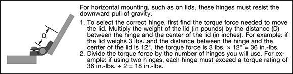
About Hinges
More
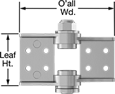
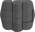
Friction Hinges
Constant resistance through the full range of motion holds lids, panels, and doors at any angle. All hinges have a nonremoveable pin to deter tampering. Style 3 includes a snap-on cover to hide the mounting fasteners.
304 stainless steel hinges are more corrosion resistant than zinc and aluminum. They also have good chemical resistance.
![]() For technical drawings and 3-D models, click on a part number.
For technical drawings and 3-D models, click on a part number.
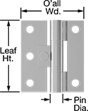
Door Leaf | Frame Leaf | |||||||||||||||
|---|---|---|---|---|---|---|---|---|---|---|---|---|---|---|---|---|
| Ht. | Wd. | Ht. | Wd. | O'all Wd. | Leaf Thick. | Range of Motion | Torque, in.-lbs. | Pin Dia. | Pin Material | Mounting Fasteners Included | No. of Mounting Holes | Mounting Hole Style | Mounting Screw Size | Each | ||
304 Stainless Steel—Dull | ||||||||||||||||
| 2 | 1 9/16" | 11/16" | 1 9/16" | 11/16" | 1 3/8" | 0.063" | 180° | 4 | 5/32" | 303 Stainless Steel | No | 5 | Straight | No. 8 | 000000 | 000000 |
| 2 | 1 15/16" | 27/32" | 1 15/16" | 27/32" | 1 11/16" | 0.078" | 180° | 8 | 15/64" | 303 Stainless Steel | No | 5 | Straight | No. 8 | 000000 | 00000 |
| 2 | 1 15/16" | 27/32" | 1 15/16" | 27/32" | 1 11/16" | 0.078" | 180° | 15 | 15/64" | 303 Stainless Steel | No | 5 | Straight | No. 8 | 000000 | 00000 |
| 2 | 3 9/16" | 1 5/8" | 3 9/16" | 1 5/8" | 3 1/4" | 0.094" | 180° | 30 | 5/16" | 303 Stainless Steel | No | 8 | Straight | No. 8 | 000000 | 00000 |
| 2 | 3 9/16" | 1 5/8" | 3 9/16" | 1 5/8" | 3 1/4" | 0.094" | 180° | 50 | 5/16" | 303 Stainless Steel | No | 8 | Straight | No. 8 | 000000 | 00000 |
304 Stainless Steel—Polished | ||||||||||||||||
| 3 | 2 1/8" | 27/32" | 1 15/16" | 27/32" | 1 11/16" | 0.078" | 180° | 20 | 17/32" | 303 Stainless Steel | No | 6 | Straight | No. 6, No. 8 | 000000 | 00000 |
| 3 | 2 1/8" | 27/32" | 1 15/16" | 27/32" | 1 11/16" | 0.078" | 180° | 30 | 17/32" | 303 Stainless Steel | No | 6 | Straight | No. 6, No. 8 | 000000 | 00000 |
| 3 | 2 1/8" | 1 9/16" | 1 7/8" | 1 9/16" | 3 1/8" | 0.078" | 180° | 40 | 29/32" | 303 Stainless Steel | No | 6 | Straight | No. 10, No. 8 | 000000 | 00000 |
| 3 | 2 1/8" | 1 9/16" | 1 7/8" | 1 9/16" | 3 1/8" | 0.078" | 180° | 60 | 29/32" | 303 Stainless Steel | No | 6 | Straight | No. 10, No. 8 | 000000 | 00000 |
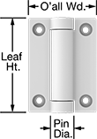
Adjustable-Friction Hinges

Tighten or loosen an adjustment screw to change the hinge resistance. Constant resistance through the full range of motion holds lids, panels, and doors at any angle. These hinges discourage tampering, since they can’t be taken apart without damaging the hinge. Capacity is based on one hinge per door.
Stainless steel hinges are stronger and more corrosion resistant than plastic hinges.
![]() For technical drawings and 3-D models, click on a part number.
For technical drawings and 3-D models, click on a part number.
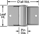
Door Leaf | Frame Leaf | Mounting | ||||||||||||||
|---|---|---|---|---|---|---|---|---|---|---|---|---|---|---|---|---|
| Ht. | Wd. | Thick. | Ht. | Wd. | Thick. | O'all Wd. | Range of Motion | Cap., lbs. | Torque, in.-lbs. | Max. Temp., °F | Fasteners Included | No. of Holes | Hole Style | Screw Size | Each | |
430 Stainless Steel | ||||||||||||||||
| 1 11/16" | 1 1/8" | 0.197" | 1 7/16" | 1 1/8" | 0.098" | 3 5/32" | 85° | Not Rated | 70 | Not Rated | No | 8 | Straight | M4.5 | 00000000 | 000000 |
Plastic Friction Hinges
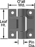
Plastic hinges are a lightweight alternative to metal hinges and provide smooth, silent operation. Constant resistance through the full range of motion holds lids, panels, and doors at any angle. All of these hinges have a nonremoveable pin to deter tampering.
Acetal hinges are more moisture resistant than nylon.
![]() For technical drawings and 3-D models, click on a part number.
For technical drawings and 3-D models, click on a part number.
Door Leaf | Frame Leaf | |||||||||||||||
|---|---|---|---|---|---|---|---|---|---|---|---|---|---|---|---|---|
| Ht. | Wd. | Ht. | Wd. | O'all Wd. | Leaf Thick. | Range of Motion | Torque, in.-lbs. | Pin Dia. | Pin Material | Max. Temp., °F | Mounting Fasteners Included | No. of Mounting Holes | Mounting Hole Style | Mounting Screw Size | Each | |
White Acetal Plastic | ||||||||||||||||
| 13/16" | 1/2" | 13/16" | 1/2" | 1" | 0.079" | 260° | 0.6 | 1/8" | 304 Stainless Steel | Not Rated | No | 4 | Countersunk | M2 | 00000000 | 00000 |
| 1 3/16" | 1/2" | 1 3/16" | 1/2" | 1" | 0.079" | 260° | 1.2 | 1/8" | 304 Stainless Steel | Not Rated | No | 4 | Countersunk | M3 | 00000000 | 0000 |
| 1 9/16" | 9/16" | 1 9/16" | 9/16" | 1 1/8" | 0.079" | 255° | 2 | 1/8" | 304 Stainless Steel | Not Rated | No | 4 | Countersunk | M3 | 00000000 | 0000 |
Black Acetal Plastic | ||||||||||||||||
| 13/16" | 1/2" | 13/16" | 1/2" | 1" | 0.063" | 260° | 0.6 | 1/8" | 304 Stainless Steel | Not Rated | No | 4 | Countersunk | M2 | 000000 | 0000 |
| 1 3/16" | 1/2" | 1 3/16" | 1/2" | 1" | 0.063" | 260° | 1.2 | 1/8" | 304 Stainless Steel | Not Rated | No | 4 | Countersunk | M3 | 000000 | 0000 |
| 1 9/16" | 9/16" | 1 9/16" | 9/16" | 1 1/8" | 0.125" | 255° | 2 | 1/8" | 304 Stainless Steel | Not Rated | No | 4 | Countersunk | M3 | 000000 | 0000 |
Multi-Axis Friction Hinges
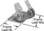
In addition to rotating 360°, these hinges tilt up and down. Constant resistance through the full range of motion holds lids, panels, and doors at any angle.
![]() For technical drawings and 3-D models, click on a part number.
For technical drawings and 3-D models, click on a part number.
Door Leaf | Frame Leaf | Rotation | Tilt | |||||||||||
|---|---|---|---|---|---|---|---|---|---|---|---|---|---|---|
| Ht. | Wd. | Ht. | Wd. | Range of Motion | Range of Motion | Torque, in.-lbs. | Range of Motion | Torque, in.-lbs. | Mounting Fasteners Included | No. of Mounting Holes | Mounting Hole Style | Mounting Screw Size | Each | |
430 Stainless Steel—Polished | ||||||||||||||
| 1 3/16" | 2 1/8" | 1 3/16" | 2 3/8" | 200° | 360° | 13 | 200° | 26 | No | 8 | Straight | M4 | 0000000 | 000000 |
| 1 7/16" | 2" | 2" | 3" | 200° | 360° | 27 | 360° | 62 | No | 8 | Countersunk | M4 | 0000000 | 00000 |
Set-Angle Position Hinges
A stop keeps these hinges open at a set angle; push past the stop to open them to 180°. All have a nonremoveable pin to deter tampering. Capacity is based on one hinge per door.
Hinges with a snap-on cover hide the mounting screws.
![]() For technical drawings and 3-D models, click on a part number.
For technical drawings and 3-D models, click on a part number.
Door Leaf | Frame Leaf | ||||||||||||||||
|---|---|---|---|---|---|---|---|---|---|---|---|---|---|---|---|---|---|
| Set Angle | Ht. | Wd. | Ht. | Wd. | O'all Wd. | Leaf Thick. | Range of Motion | Capacity, lbs. | Torque, in.-lbs. | Pin Dia. | Pin Material | Max. Temp., °F | Mounting Fasteners Included | No. of Mounting Holes | Mounting Screw Size | Each | |
Hinge with Snap-On Cover | |||||||||||||||||
Black Acetal Plastic | |||||||||||||||||
| 45°, 90°, 135° | 2 3/4" | 1 9/16" | 2 3/4" | 1 9/16" | 3 3/16" | 0.354" | 180° | 17 | 17.5 | 19/32" | Stainless Steel | Not Rated | No | 8 | No. 10 | 00000000 | 000000 |
| 80° | 1 15/16" | 1 1/8" | 1 15/16" | 1 1/8" | 2 1/4" | 0.360" | 180° | 100 | 10 | 29/64" | Stainless Steel | 180° | No | 4 | No. 10 | 00000000 | 00000 |
| 80° | 2 1/16" | 1 3/16" | 2 1/16" | 1 3/16" | 2 5/16" | 0.291" | 180° | 100 | 6 | 17/32" | Stainless Steel | 180° | No | 4 | No. 10 | 000000000 | 00000 |
| 80° | 2 1/16" | 1 3/16" | 2 1/16" | 1 3/16" | 2 5/16" | 0.291" | 180° | 100 | 15 | 17/32" | Stainless Steel | 180° | No | 4 | No. 10 | 000000000 | 00000 |
| 90° | 2" | 1 3/16" | 2" | 1 3/16" | 2 3/8" | 0.313" | 180° | Not Rated | 5 | 11/64" | 303 Stainless Steel | 180° | No | 4 | No. 8 | 00000000 | 0000 |
| 115° | 1 15/16" | 1 1/8" | 1 15/16" | 1 1/8" | 2 1/4" | 0.360" | 180° | 100 | 10 | 29/64" | Stainless Steel | 180° | No | 4 | No. 10 | 00000000 | 00000 |
| 115° | 2 1/16" | 1 3/16" | 2 1/16" | 1 3/16" | 2 5/16" | 0.291" | 180° | 100 | 6 | 17/32" | Stainless Steel | 180° | No | 4 | No. 10 | 000000000 | 00000 |
| 115° | 2 1/16" | 1 3/16" | 2 1/16" | 1 3/16" | 2 5/16" | 0.291" | 180° | 100 | 15 | 17/32" | Stainless Steel | 180° | No | 4 | No. 10 | 000000000 | 00000 |
| 150° | 1 15/16" | 1 1/8" | 1 15/16" | 1 1/8" | 2 1/4" | 0.360" | 180° | 100 | 10 | 29/64" | Stainless Steel | 180° | No | 4 | No. 10 | 00000000 | 00000 |
| 150° | 2 1/16" | 1 3/16" | 2 1/16" | 1 3/16" | 2 5/16" | 0.291" | 180° | 100 | 6 | 17/32" | Stainless Steel | 180° | No | 4 | No. 10 | 000000000 | 00000 |
| 150° | 2 1/16" | 1 3/16" | 2 1/16" | 1 3/16" | 2 5/16" | 0.291" | 180° | 100 | 15 | 17/32" | Stainless Steel | 180° | No | 4 | No. 10 | 000000000 | 00000 |
White Acetal Plastic | |||||||||||||||||
| 90° | 2" | 1 3/16" | 2" | 1 3/16" | 2 3/8" | 0.313" | 180° | Not Rated | 5 | 11/64" | 303 Stainless Steel | 180° | No | 4 | No. 8 | 00000000 | 0000 |
Lever-Lock Position Hinges
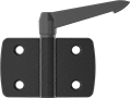
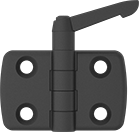
Lock these hinges open at any angle within their range of motion. Pull the lever up and turn it a quarter turn to make adjustments. All hinges have a nonremoveable pin to deter tampering.
Zinc hinges have mild corrosion resistance.
Nickel-plated aluminum hinges are about half the weight of zinc hinges. They have mild corrosion resistance.
Nylon hinges are a lightweight alternative to metal hinges. They open as wide as 220°.
![]() For technical drawings and 3-D models, click on a part number.
For technical drawings and 3-D models, click on a part number.
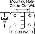
Door Leaf | Frame Leaf | |||||||||||||||
|---|---|---|---|---|---|---|---|---|---|---|---|---|---|---|---|---|
| Ht. | Wd. | Ht. | Wd. | O'all Wd. | Leaf Thick. | Range of Motion | Pin Dia. | Pin Material | Handle Material | Mounting Fasteners Included | Number of Mounting Holes | Mounting Hole Ctr.-to-Ctr. Wd. | Mounting Hole Style | Mounting Screw Size | Each | |
Black Zinc—Polished | ||||||||||||||||
| 1 1/2" | 1 7/16" | 1 1/2" | 1 7/16" | 3" | 0.315" | 180° | 1/4" | 304 Stainless Steel | Black Nylon | No | 4 | 1 25/32" | Straight | M8 | 0000000 | 000000 |
| 1 1/2" | 1 7/16" | 1 1/2" | 1 7/16" | 3" | 0.315" | 180° | 1/4" | 304 Stainless Steel | Black Nylon | No | 4 | 1 7/8" | Straight | M8 | 0000000 | 00000 |
| 1 1/2" | 1 7/16" | 1 1/2" | 1 7/16" | 3" | 0.315" | 180° | 1/4" | 304 Stainless Steel | Black Nylon | No | 4 | 1 31/32" | Straight | M8 | 0000000 | 00000 |
Black Nickel-Plated Aluminum—Dull | ||||||||||||||||
| 1 7/8" | 1 3/16" | 1 7/8" | 1 3/16" | 2 3/8" | 0.315" | 180° | 1/4" | 304 Stainless Steel | Black Nylon | No | 4 | 1 3/8" | Countersunk | M6 | 0000000 | 00000 |
| 1 7/8" | 1 1/2" | 1 7/8" | 1 1/2" | 3" | 0.315" | 180° | 1/4" | 304 Stainless Steel | Black Nylon | No | 4 | 1 25/32" | Countersunk | M6 | 0000000 | 00000 |
| 1 7/8" | 1 29/32" | 1 7/8" | 1 29/32" | 3 13/16" | 0.315" | 180° | 1/4" | 304 Stainless Steel | Black Nylon | No | 4 | 2 5/32" | Countersunk | M6 | 0000000 | 00000 |
| 1 7/8" | 2 9/32" | 1 7/8" | 2 9/32" | 4 9/16" | 0.315" | 180° | 1/4" | 304 Stainless Steel | Black Nylon | No | 4 | 2 9/16" | Countersunk | M6 | 0000000 | 00000 |
Black Nylon—Dull | ||||||||||||||||
| 1 7/8" | 1" | 1 7/8" | 1" | 2" | 0.315" | 220° | 1/4" | 304 Stainless Steel | Black Nylon | No | 4 | 1 3/16" | Countersunk | M6 | 0000000 | 00000 |
| 1 7/8" | 1 3/16" | 1 7/8" | 1 3/16" | 2 5/16" | 0.315" | 220° | 1/4" | 304 Stainless Steel | Black Nylon | No | 4 | 1 3/8" | Countersunk | M6 | 0000000 | 00000 |
| 1 7/8" | 1 13/32" | 1 7/8" | 1 13/32" | 2 7/8" | 0.315" | 220° | 1/4" | 304 Stainless Steel | Black Nylon | No | 4 | 1 9/16" | Countersunk | M6 | 0000000 | 00000 |
| 1 7/8" | 1 1/2" | 1 7/8" | 1 1/2" | 3" | 0.315" | 220° | 1/4" | 304 Stainless Steel | Black Nylon | No | 4 | 1 25/32" | Countersunk | M6 | 0000000 | 00000 |
| 1 7/8" | 1 23/32" | 1 7/8" | 1 23/32" | 3 7/16" | 0.315" | 220° | 1/4" | 304 Stainless Steel | Black Nylon | No | 4 | 2" | Countersunk | M6 | 0000000 | 00000 |
| 1 7/8" | 1 7/8" | 1 7/8" | 1 7/8" | 3 13/16" | 0.315" | 220° | 1/4" | 304 Stainless Steel | Black Nylon | No | 4 | 2 5/32" | Countersunk | M6 | 0000000 | 00000 |
| 1 7/8" | 2 1/4" | 1 7/8" | 2 1/4" | 4 1/2" | 0.315" | 220° | 1/4" | 304 Stainless Steel | Black Nylon | No | 4 | 2 9/16" | Countersunk | M6 | 0000000 | 00000 |
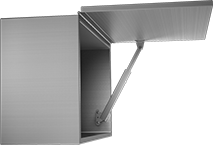
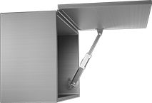
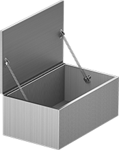
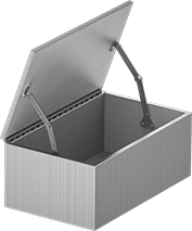
Self-Opening Lid Supports
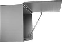
Springs provide lifting assistance to raise and hold lids open—slightly lift the lid to get it started and the support will do the rest. Manually shut the lids and the supports will hold them in the closed position. All of these supports are rated for maximum lid weight—do not exceed the weight listed. They can be used individually but should be used in pairs for lids longer than 24". They are reversible for right-side or left-side mounting positions.
Supports for lids that open up from the side are often used in overhead installations.
Supports for lids that open up from the top are often used on crates, hatches, and tool chests.
![]() For technical drawings and 3-D models, click on a part number.
For technical drawings and 3-D models, click on a part number.
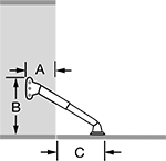
Min. Mounting | For Max. Lid Weight, lbs. | Mounting | ||||||||||||
|---|---|---|---|---|---|---|---|---|---|---|---|---|---|---|
| Dp. (A) | Clearance (B) | Lid Mounting Clearance (C) | For Lid Opening Angle | One Lid Support | Two Lid Supports | Material | Appearance | Spring Material | Hold Lid Closed | Hardware Included | Screw Size | No. of Holes | Each | |
Side Mount, Opens Up or Top Mount, Opens Up | ||||||||||||||
| 2.2" | 10.83" | 3.44" | 90° | 2.75 | 5.5 | 304 Stainless Steel | Dull | Nickel Steel | Yes | No | No. 6 | 5 | 00000000 | 000000 |
| 2.2" | 15.43" | 4.23" | 90° | 3.4 | 6.8 | 304 Stainless Steel | Dull | Nickel Steel | Yes | No | No. 6 | 5 | 00000000 | 00000 |
Top Mount, Opens Up | ||||||||||||||
| 2.2" | 14.13" | 4.82" | 110° | 2.75 | 5.5 | 304 Stainless Steel | Dull | Nickel Steel | Yes | No | No. 6 | 5 | 00000000 | 00000 |
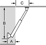
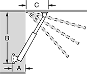
Lid Supports
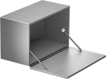
Manually control these standard free-moving lid supports through their full range of motion. Raise or lower the lid until the hold-open mechanism on the support is engaged; slightly lift it again to release the hold and close the lid. To secure the lid in a closed position, use a latch or lock (not included). These supports are rated for maximum lid weight—do not exceed the weight listed. They can be used individually but should be used in pairs for lids longer than 24". All are reversible for right-side or left-side mounting positions.
Supports for lids that open up from the side are often used in overhead installations.
Supports for lids that open down from the side allow lids to double as a work surface when they are open, similar to a drop-leaf desk.
![]() For technical drawings and 3-D models, click on a part number.
For technical drawings and 3-D models, click on a part number.
Min. Mounting | For Max. Lid Weight, lbs. | Mounting | |||||||||||
|---|---|---|---|---|---|---|---|---|---|---|---|---|---|
| Dp. (A) | Clearance (B) | Lid Mounting Clearance (C) | For Lid Opening Angle | One Lid Support | Two Lid Supports | Material | Appearance | Hold Lid Closed | Hardware Included | Screw Size | No. of Holes | Each | |
Side Mount, Opens Up | |||||||||||||
| 1.81" | 9.21" | 4.13" | 75° | 33 | 66 | 304 Stainless Steel | Dull | No | No | No. 6, No. 8 | 5 | 00000000 | 000000 |
| 1.81" | 11.3" | 5.12" | 90° | 33 | 66 | 304 Stainless Steel | Dull | No | No | No. 6, No. 8 | 5 | 00000000 | 00000 |
Side Mount, Opens Down | |||||||||||||
| 7.09" | 5" | 5" | 90° | 22 | 44 | 304 Stainless Steel | Dull | No | No | No. 8 | 4 | 00000000 | 00000 |
| 8.27" | 5.85" | 5.85" | 90° | 26 | 52 | 304 Stainless Steel | Dull | No | No | No. 8 | 4 | 00000000 | 00000 |
| 9.45" | 6.68" | 6.68" | 90° | 28 | 56 | 304 Stainless Steel | Dull | No | No | No. 8 | 4 | 00000000 | 00000 |
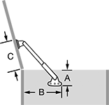
High-Capacity Lid Supports
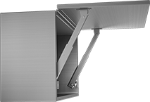
Hold heavy lids open with these supports. They mount to the side, so they’re often used in overhead installations. Raise the lid until the hold-open mechanism on the support is engaged; slightly lift it again to release the hold and close the lid. To secure the lid in a closed position, use a latch or lock (not included). All of these supports are rated for maximum lid weight—do not exceed the weight listed. They can be used individually but should be used in pairs for lids longer than 24".
Manually control free-moving supports through their full range of motion.
Ratchet supports hold lids still at multiple angles.
![]() For technical drawings and 3-D models, click on a part number.
For technical drawings and 3-D models, click on a part number.
Min. Mounting | For Max. Lid Weight, lbs. | Mounting | ||||||||||||
|---|---|---|---|---|---|---|---|---|---|---|---|---|---|---|
| Dp. (A) | Clearance (B) | Lid Mounting Clearance (C) | For Lid Opening Angle | One Lid Support | Two Lid Supports | Material | Appearance | Mounting Position | Hold Lid Closed | Hardware Included | Screw Size | No. of Holes | Each | |
Side Mount, Opens Up | ||||||||||||||
Free Moving | ||||||||||||||
| 2" | 14.66" | 5.91" | 90° | 293 | 586 | 304 Stainless Steel | Dull | Reversible | No | No | No. 10 | 6 | 0000000 | 0000000 |
| 2" | 18.66" | 7.48" | 90° | 214 | 428 | 304 Stainless Steel | Dull | Reversible | No | No | No. 10 | 6 | 0000000 | 000000 |
Ratchet | ||||||||||||||
| 2" | 14.92" | 5.91" | 45°-90° | 154 | 308 | 304 Stainless Steel | Dull | Left Side | No | No | M5 | 6 | 0000000 | 000000 |
| 2" | 14.92" | 5.91" | 45°-90° | 154 | 308 | 304 Stainless Steel | Dull | Right Side | No | No | M5 | 6 | 0000000 | 000000 |
| 2" | 18.07" | 7.48" | 45°-90° | 154 | 308 | 304 Stainless Steel | Dull | Left Side | No | No | M5 | 6 | 0000000 | 000000 |
| 2" | 18.07" | 7.48" | 45°-90° | 154 | 308 | 304 Stainless Steel | Dull | Right Side | No | No | M5 | 6 | 0000000 | 000000 |
Clean Room Lid Supports
Keep environments free of contaminants—with plastic bushings, there's no metal-to-metal contact that can release particles as these supports open and close. Manually control these free-moving lid supports through their full range of motion. Raise the lid until the hold-open mechanism on the support is engaged; slightly lift it again to release the hold and close the lid. To secure the lid in a closed position, use a latch or lock (not included; see our clean room magnetic latches).
These supports can be used on lids that open up from the side, which are good for overhead installations, and on lids that open up from the top, which are good for crates, hatches, and tool chests. They are rated for maximum lid weight—do not exceed the weight listed. The supports can be used individually but should be used in pairs for lids longer than 24". They are reversible for right-side or left-side mounting positions.
Min. Mounting | For Max. Lid Weight, lbs. | Mounting | |||||||||||
|---|---|---|---|---|---|---|---|---|---|---|---|---|---|
| Dp. (A) | Clearance (B) | Lid Mounting Clearance (C) | For Lid Opening Angle | One Lid Support | Two Lid Supports | Material | Appearance | Hold Lid Closed | Hardware Included | Screw Size | No. of Holes | Each | |
Side Mount, Opens Up or Top Mount, Opens Up | |||||||||||||
| 1.57" | 8.43" | 2.81" | 90° | 33 | 66 | 304 Stainless Steel | Dull | No | No | M4 | 4 | 0000000 | 000000 |
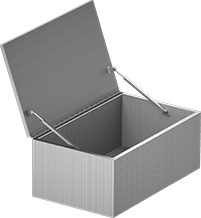
Spring Lid Supports
Also known as hatch springs, these supports are commonly used on hatches and other top-opening lids. Raise the lid to extend the spring, which props the lid open—an internal cable keeps the spring from overextending. Press the center of the spring to release the hold and close the lid. To secure the lid in a closed position, use a latch or lock (not included). These supports are rated for maximum lid weight—do not exceed the weight listed. They can be used individually but should be used in pairs for lids longer than 24". Both are reversible for right-side or left-side mounting positions.
Min. Mounting | For Max. Lid Weight, lbs. | Mounting | ||||||||||||
|---|---|---|---|---|---|---|---|---|---|---|---|---|---|---|
| Dp. (A) | Clearance (B) | Lid Mounting Clearance (C) | For Lid Opening Angle | One Lid Support | Two Lid Supports | Lg. | Dia. | Material | Hold Lid Closed | Hardware Included | Screw Size | No. of Holes | Each | |
Top Mount, Opens Up | ||||||||||||||
| 2" | 5" | 5" | 90° | 20 | 40 | 10 1/8" | 9/16" | 304 Stainless Steel | No | No | No. 10 | 4 | 0000000 | 000000 |
| 2" | 5.75" | 5.75" | 90° | 85 | 170 | 11 5/8" | 7/8" | 304 Stainless Steel | No | No | No. 10 | 8 | 0000000 | 00000 |
| 2.5" | 6.36" | 3.86" | 90° | 20 | 40 | 9" | 7/16" | 304 Stainless Steel | No | No | No. 6 | 4 | 0000000 | 00000 |
Friction Lid Supports
 Top Mount, Opens Up | 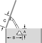 | 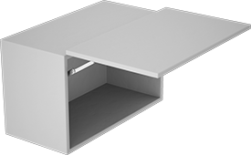 Side Mount, Opens Up |
Free Moving |
Providing constant resistance through the full range of motion, these supports hold lids open at any angle up to 70° or 90°. Simply raise or lower the lid and let go—friction keeps it in position. These supports can be used individually but should be used in pairs for lids longer than 24". Mounting position is determined as you look into your cabinet or chest.
Supports for lids that open up from the top are often used on crates, hatches, and tool chests.
Supports for lids that open up from the side are often used in overhead installations.
All of these supports are rated for torque instead of maximum lid weight. Calculate your lid's torque and make sure it falls within the range listed—too much torque will cause your lid to slam; too little will prevent it from closing. Torque = Lid Height (inches) × 0.5 × Lid Weight (lbs.).
Min. Mounting | Torque Range, in.-lbs. | Mounting | ||||||||||||
|---|---|---|---|---|---|---|---|---|---|---|---|---|---|---|
| Dp. (A) | Clearance (B) | Lid Mounting Clearance (C) | Hold-Open Angle | One Lid Support | Two Lid Supports | Material | Appearance | Mounting Position | Hold Lid Closed | Hardware Included | Screw Size | No. of Holes | Each | |
Top Mount, Opens Up | ||||||||||||||
| 2.32" | 6.5" | 6.75" | 0°-70° | 22 to 31 | 43 to 63 | 430 Stainless Steel | Dull | Left Side | Yes | No | M4 | 4 | 0000000 | 000000 |
| 2.32" | 6.5" | 6.75" | 0°-70° | 22 to 31 | 43 to 63 | 430 Stainless Steel | Dull | Right Side | Yes | No | M4 | 4 | 0000000 | 00000 |
Side Mount, Opens Up | ||||||||||||||
| 1.5" | 3.31" | 3.46" | 0°-70° | 11 to 15 | 16 to 23 | 430 Stainless Steel | Dull | Left Side | Yes | Yes | __ | __ | 0000000 | 00000 |
| 1.5" | 3.31" | 3.46" | 0°-70° | 11 to 15 | 16 to 23 | 430 Stainless Steel | Dull | Right Side | Yes | Yes | __ | __ | 0000000 | 00000 |
Frame-Mount Door Holders
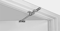
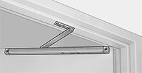
Hold doors open within the 85° to 110° range without adding clutter to your floor or walls. The hold-open function can be turned on or off by turning a knob or nut on the holder. In the off position, holders act as a shock-absorbing stop to prevent doors from opening too far.
Holders with a 1 7/8" minimum required door-to-frame clearance have a broader mounting footprint than those with 7/8" minimum required door-to-frame clearance for increased stability.
| Min. Required Door-to-Frame Clearance | For Door Opening Wd. | Material | Rod Dia. | Mounting Hardware Included | Each | |
| 7/8" | 27 1/16"-33" | Dull Bronze-Plated 300 Series Stainless Steel | 1/2" | Yes | 0000000 | 0000000 |
| 7/8" | 27 1/16"-33" | Dull Chrome-Plated 300 Series Stainless Steel | 1/2" | Yes | 0000000 | 000000 |
| 7/8" | 33 1/16"-39" | Dull Bronze-Plated 300 Series Stainless Steel | 1/2" | Yes | 0000000 | 000000 |
| 7/8" | 33 1/16"-39" | Dull Chrome-Plated 300 Series Stainless Steel | 1/2" | Yes | 0000000 | 000000 |
| 1 7/8" | 27 1/16"-33" | Dull 300 Series Stainless Steel | __ | Yes | 0000000 | 000000 |
| 1 7/8" | 33 1/16"-39" | Dull 300 Series Stainless Steel | __ | Yes | 0000000 | 000000 |
| 1 7/8" | 45 1/16"-54" | Dull 300 Series Stainless Steel | __ | Yes | 0000000 | 000000 |
Fold-Away Brackets for Drop-Leaf Shelves
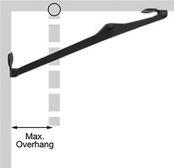
Brackets are designed to be used in pairs. To ensure proper operation, do not exceed the maximum overhang listed.
Stainless steel bracket is corrosion resistant.
![]() For technical drawings and 3-D models, click on a part number.
For technical drawings and 3-D models, click on a part number.
| For Max. Overhang | Extended Lg. | Overall Wd. | Cap., lbs. | Release Type | Appearance | Mounting Fasteners Included | Screw Size | Each | |
Stainless Steel | |||||||||
|---|---|---|---|---|---|---|---|---|---|
| 3 7/8" | 11 5/8" | 1 3/4" | 7 | Pull Ring | Polished | No | No. 10 | 0000000 | 000000 |
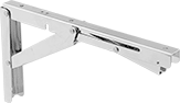
Heavy Duty Fold-Away Shelf Brackets
These brackets have greater weight capacities than standard duty fold-away shelf brackets.
Style B brackets are stainless steel. They’re more corrosion resistant than steel and galvanized steel brackets. Brackets with a speed limiter fold softly and safely.
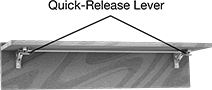
Add quick-release levers to release multiple brackets at the same time.
Speed limiters prevent slamming, cushioning brackets so they fold down softly and safely.
![]() For technical drawings and 3-D models, click on a part number.
For technical drawings and 3-D models, click on a part number.
Brackets | |||||||||||||
|---|---|---|---|---|---|---|---|---|---|---|---|---|---|
Overall | Optional Speed Limiters | ||||||||||||
| Dp. | Ht. | Wd. | Projection | Cap., lbs. | Appearance | Mounting Fasteners Included | Screw Size | Specifications Met | Features | Each | Each | ||
Style B—Stainless Steel | |||||||||||||
| 7 7/8" | 4 5/8" | 1 1/8" | 1 1/8" | 380 | Polished | No | 3/16" | NSF/ANSI 2 | __ | 00000000 | 000000 | 00000000 | 0000000 |
| 12" | 6 1/2" | 1" | 1 1/4" | 330 | Polished | No | 3/16" | __ | Speed Limiter | 00000000 | 00000 | 000000 | 00 |
| 12" | 6 1/2" | 1 1/4" | 1 1/4" | 330 | Polished | No | No. 10 | NSF/ANSI 2 | __ | 00000000 | 00000 | 00000000 | 000000 |
| 12 1/2" | 6 3/4" | 1 3/8" | 1 1/8" | 440 | Polished | No | 1/4" | NSF/ANSI 2 | __ | 00000000 | 00000 | 00000000 | 000000 |