


About Push-to-Close Latches
More
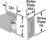
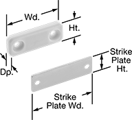
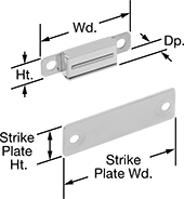
Grab Latches
A catch grabs and holds the strike plate to keep doors shut.
![]() For technical drawings and 3-D models, click on a part number.
For technical drawings and 3-D models, click on a part number.
Strike Plate | Mounting | |||||||||||||
|---|---|---|---|---|---|---|---|---|---|---|---|---|---|---|
| Material | Wd. | Dp. | Max. Pull Strength, lbs. | Projection | Mounting Hole Ctr.-to-Ctr. | Ht. | Wd. | Mounting Hole Ctr.-to-Ctr. | Roller Material | Fasteners Included | Screw Size | Each | ||
Roller Grab | ||||||||||||||
Surface Mount—Screw On | ||||||||||||||
| 3 | 304 Stainless Steel | 1 7/8" | 5/8" | 6 | 5/8" | 1 9/16" | 1/4" | 1 5/16" | 1" | Plastic | No | No. 4 | 000000 | 00000 |
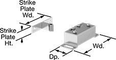
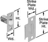
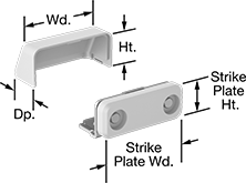
Multidirectional Ball-Style Grab Latches
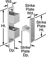
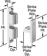
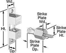
Each latch has top and bottom spring-loaded balls that can grab the strike plate from different directions.
Latches with a force adjustment screw allow adjustments to the force needed to open and close the latches.
Brass latches have good corrosion resistance and are nonmagnetic.
316 stainless steel latches have excellent corrosion resistance.
![]() For technical drawings and 3-D models, click on a part number.
For technical drawings and 3-D models, click on a part number.
Strike Plate | ||||||||||||||
|---|---|---|---|---|---|---|---|---|---|---|---|---|---|---|
| Material | Ht. | Wd. | Dp. | Max. Pull Strength, lbs. | Mounting Hole Ctr.-to-Ctr. | Ht. | Wd. | Dp. | Mounting Hole Ctr.-to-Ctr. | Ball Material | Mounting Fasteners Included | Features | Each | |
Ball Grab | ||||||||||||||
Left and Right Grab Direction | ||||||||||||||
| Bronze-Plated Brass | 2 3/16" | 1/2" | 1/2" | 4 | 1 3/4" | 1 3/8" | 3/8" | 5/8" | 15/16" | 304 Stainless Steel | Yes | Force Adjustment Screw | 0000000 | 000000 |
| Chrome-Plated Brass | 2 3/16" | 1/2" | 1/2" | 4 | 1 3/4" | 1 3/8" | 3/8" | 5/8" | 15/16" | 304 Stainless Steel | Yes | Force Adjustment Screw | 000000 | 00000 |
| Brass | 2 3/16" | 1/2" | 1/2" | 4 | 1 3/4" | 1 3/8" | 3/8" | 5/8" | 15/16" | 304 Stainless Steel | Yes | Force Adjustment Screw | 0000000 | 00000 |
Left, Right, and Front Grab Direction | ||||||||||||||
| 316 Stainless Steel | 1 11/16" | 5/16" | 3/8" | 3 | 1 3/8" | 1" | 5/16" | 7/16" | 5/8" | 316 Stainless Steel | Yes | __ | 000000 | 00000 |
| 316 Stainless Steel | 2" | 3/8" | 1/2" | 4 | 1 9/16" | 1 3/16" | 3/8" | 1/2" | 13/16" | 316 Stainless Steel | Yes | __ | 000000 | 00000 |
| 316 Stainless Steel | 2 3/4" | 1/2" | 11/16" | 9 | 2 3/8" | 1 11/16" | 7/16" | 3/4" | 1 3/16" | 316 Stainless Steel | Yes | __ | 000000 | 00000 |
| 316 Stainless Steel | 3 3/8" | 5/8" | 9/16" | 21 | 2 13/16" | 2 1/16" | 5/8" | 15/16" | 1 1/4" | 316 Stainless Steel | Yes | Force Adjustment Screw | 0000000 | 000000 |
Left, Right, Front, and Back Grab Direction | ||||||||||||||
| Bronze-Plated Brass | 3" | 3/4" | 3/4" | 8 | 2 1/2" | 3/4" | 13/16" | 1 1/2" | __ | 304 Stainless Steel | Yes | Force Adjustment Screw | 0000000 | 00000 |
| Chrome-Plated Brass | 3" | 3/4" | 3/4" | 4 | 2 1/2" | 1 3/4" | 7/16" | 7/8" | 1 1/4" | 304 Stainless Steel | Yes | Force Adjustment Screw | 000000 | 00000 |
| Chrome-Plated Brass | 3" | 3/4" | 3/4" | 8 | 2 1/2" | 3/4" | 13/16" | 1 1/2" | __ | 304 Stainless Steel | Yes | Force Adjustment Screw | 0000000 | 00000 |
| Brass | 3" | 3/4" | 3/4" | 4 | 2 1/2" | 1 3/4" | 7/16" | 7/8" | 1 1/4" | 304 Stainless Steel | Yes | Force Adjustment Screw | 000000 | 00000 |
| Brass | 3" | 3/4" | 3/4" | 8 | 2 1/2" | 3/4" | 13/16" | 1 1/2" | __ | 304 Stainless Steel | Yes | Force Adjustment Screw | 0000000 | 00000 |
Soft-Close Heavy Duty Roller Latches
To prevent doors from slamming, these latches are hydraulic. Mount them vertically at the top of walk-in freezer doors. The arm rolls into the strike plate as the door closes for a secure hold. A firm tug releases the roller and opens the door. Door offset is the space between the door face and the frame when the door is closed.
![]() For technical drawings and 3-D models, click on a part number.
For technical drawings and 3-D models, click on a part number.
| Material | Ht. | Wd. | Dp. | Roller Material | Mounting Fasteners Included | Each | |
| 304 Stainless Steel | 7 7/8" | 1 15/16" | 2 1/2" | Rubber | Yes | 00000000 | 0000000 |
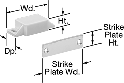
Roller Latches
Doors stay closed with the pressure of rollers against the strike plate.
Styles 3-5 latches have a projection adjustment screw to adjust the roller projection from 0" to 3/8" to compensate for misalignment.
![]() For technical drawings and 3-D models, click on a part number.
For technical drawings and 3-D models, click on a part number.
Strike Plate | For Cutout | Mounting | |||||||||||||||
|---|---|---|---|---|---|---|---|---|---|---|---|---|---|---|---|---|---|
| Style | Material | Ht. | Wd. | Dp. | Max. Pull Strength, lbs. | Mounting Hole Ctr.-to-Ctr. | Ht. | Wd. | Mounting Hole Ctr.-to-Ctr. | Ht. | Wd. | Dp. | Roller Material | Fasteners Included | Screw Size | Each | |
Surface Mount | |||||||||||||||||
| 3 | 304 Stainless Steel | 2" | __ | 1 7/16" | 17 | 1" | 2 1/8" | 1" | 1 1/2" | __ | __ | __ | Plastic | Yes | No. 6 | 0000000 | 000000 |
Mortise Mount | |||||||||||||||||
| 4 | 304 Stainless Steel | 2 1/4" | 1" | __ | 17 | 1 5/8" | 2 3/4" | 1 1/8" | 2 1/8" | 7/8" | 7/8" | 2" | Plastic | Yes | No. 8 | 0000000 | 00000 |
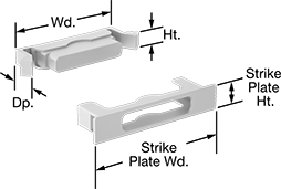
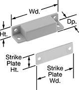
Magnetic Latches
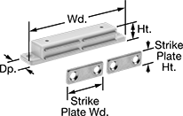
Magnetic force holds doors closed. These latches can often be found on audio/visual cabinets. Note: Maximum pull-strength rating given is based on installation with the furnished strike plate; pull strength may be different based on the application.
Styles 2 and 7 have a two-piece strike plate for double doors that meet in the center.
![]() For technical drawings and 3-D models, click on a part number.
For technical drawings and 3-D models, click on a part number.
Magnetic Latches | ||||||||||||||||
|---|---|---|---|---|---|---|---|---|---|---|---|---|---|---|---|---|
Strike Plate | Mounting | Replacement Strike Plates | ||||||||||||||
| Style | Max. Pull Strength, lbs. | Ht. | Wd. | Dp. | Mounting Hole Ctr.-to-Ctr. | Material | Ht. | Wd. | Dp. | Mounting Hole Ctr.-to-Ctr. | Fasteners Included | Screw Size | Each | Each | ||
White Plastic | ||||||||||||||||
| 2 | 11 | 1/2" | 3 3/8" | 11/16" | 3" | Stainless Steel | 7/16" | 1 3/16" | __ | 13/16" | Yes | M2.6 | 0000000 | 00000 | 0000000 | 00000 |
| 2 | 12 | 5/8" | 4 3/16" | 13/16" | 3 11/16" | Stainless Steel | 9/16" | 1 1/2" | __ | 1" | Yes | M2.6 | 0000000 | 00000 | 0000000 | 0000 |
Stainless Steel | ||||||||||||||||
| 2 | 10 | 1/2" | 3 1/8" | 11/16" | 2 3/4" | Steel | 5/8" | 1" | __ | __ | Yes | M3 | 0000000 | 0000 | 000000 | 00 |
| 3 | 6 | 1/2" | 1 3/8" | 1/8" | 1" | Stainless Steel | 9/16" | 1 3/8" | 1/16" | 1" | Yes | M3 | 0000000 | 00000 | 0000000 | 000 |
Steel | ||||||||||||||||
| 3 | 4 | 3/8" | 1 7/16" | 3/16" | 1 1/8" | Stainless Steel | 5/8" | 1 15/16" | __ | 1 9/16" | No | M3 | 0000000 | 0000 | 0000000 | 0000 |
304 Stainless Steel | ||||||||||||||||
| 3 | 7 | 7/16" | 1 9/16" | 1/4" | 1 3/16" | Stainless Steel | 5/8" | 1 15/16" | __ | 1 9/16" | No | M4.2 | 0000000 | 0000 | 0000000 | 0000 |
430 Stainless Steel | ||||||||||||||||
| 3 | 11 | 11/16" | 1 5/8" | 1/8" | 1 1/8" | Nickel-Plated Steel | 5/8" | 1 3/16" | 1/16" | 5/8" | Yes | M3 | 0000000 | 00000 | 0000000 | 000 |
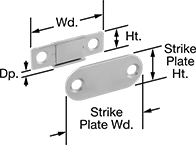
Clean Room Magnetic Latches
To keep your environments free of contaminants, the magnet is encapsulated so it won't release particles when it meets the strike plate. Magnetic force holds doors closed.
On latches with a pivoting strike plate, the strike plate moves for better contact with the magnetic latch.
Note: Maximum pull-strength rating given is based on installation with the furnished strike plate; pull strength may be different based on the application.
![]() For technical drawings and 3-D models, click on a part number.
For technical drawings and 3-D models, click on a part number.
Strike Plate | Mounting | |||||||||||||||
|---|---|---|---|---|---|---|---|---|---|---|---|---|---|---|---|---|
| Max. Pull Strength, lbs. | Material | Ht. | Wd. | Dp. | Mounting Hole Ctr.-to-Ctr. | Mounting Hole Diameter | Material | Ht. | Wd. | Mounting Hole Ctr.-to-Ctr. | Fasteners Included | Screw Size | Features | Each | ||
| 1 | 7 | White Plastic | 11/16" | 1 13/16" | 1/4" | 1 3/16" | 4.4mm, 9.6mm | Stainless Steel | 5/8" | 1 15/16" | 1 9/16" | No | No. 6, No. 8 | __ | 0000000 | 000000 |
| 2 | 7 | White Plastic | 3/4" | 1 3/4" | 1 1/16" | 1 3/16" | 4.4mm, 8.4mm | Stainless Steel | 11/16" | 1 3/4" | 1" | Yes | No. 6 | Pivoting Strike Plate | 0000000 | 00000 |
| 3 | 7 | Black Plastic | 1/2" | 2" | 13/16" | 1 9/16" | 4.4mm | Stainless Steel | 5/8" | 1 15/16" | 1 9/16" | No | M4, No. 6 | __ | 0000000 | 00000 |
| 3 | 7 | White Plastic | 9/16" | 2" | 7/8" | 1 9/16" | 4.4mm, 9.6mm | Stainless Steel | 5/8" | 1 15/16" | 1 9/16" | No | M4, No. 6 | __ | 0000000 | 00000 |
| 4 | 6 | Black Plastic | 5/16" | 1 7/8" | 11/16" | __ | __ | Stainless Steel | 3/8" | 2 1/8" | __ | __ | __ | Pivoting Strike Plate | 0000000 | 00000 |
| 4 | 6 | White Plastic | 5/16" | 1 7/8" | 11/16" | __ | __ | Stainless Steel | 3/8" | 2 1/8" | __ | __ | __ | Pivoting Strike Plate | 0000000 | 00000 |
High-Temperature Magnetic Latches
These latches withstand temperatures up to 480° or 570° F. They have a magnetic force that holds doors closed.
Note: Maximum pull-strength rating given is based on installation with the furnished strike plate; pull strength may be different based on the application.
![]() For technical drawings and 3-D models, click on a part number.
For technical drawings and 3-D models, click on a part number.
Strike Plate | Temperature Range, F° | Mounting | ||||||||||||
|---|---|---|---|---|---|---|---|---|---|---|---|---|---|---|
| Max. Pull Strength, lbs. | Ht. | Wd. | Dp. | Mounting Hole Ctr.-to-Ctr. | Mounting Hole Diameter | Ht. | Wd. | Mounting Hole Ctr.-to-Ctr. | Min. | Max. | Fasteners Included | Screw Size | Each | |
304 Stainless Steel | ||||||||||||||
| 4 | 7/16" | 1 9/16" | 5/16" | 1 3/16" | 4.2 mm | 5/8" | 1 15/16" | 1 9/16" | -145° | 480° | No | No. 6, No. 8 | 0000000 | 000000 |
| 11 | 7/16" | 1 9/16" | 5/16" | 1 3/16" | 4.2 mm | 5/8" | 1 15/16" | 1 9/16" | -145° | 480° | No | No. 6, No. 8 | 0000000 | 00000 |
| 15 | 11/16" | 2" | 9/16" | 1 9/16" | 3.5 mm | 5/8" | 1 15/16" | 1 9/16" | -145° | 480° | No | No. 6 | 0000000 | 00000 |
| 31 | 11/16" | 2" | 9/16" | 1 9/16" | 3.5 mm | 5/8" | 1 15/16" | 1 9/16" | -145° | 480° | No | No. 6 | 0000000 | 00000 |
Food Industry Magnetic Latches
Made to NSF/ANSI standards, this latch has a completely sealed magnet to eliminate crevices that can trap food particles. Magnetic force holds doors closed.
Note: Maximum pull-strength rating given is based on installation with the furnished strike plate; pull strength may be different based on the application.
![]() For technical drawings and 3-D models, click on a part number.
For technical drawings and 3-D models, click on a part number.
Strike Plate | Mounting | ||||||||||||||
|---|---|---|---|---|---|---|---|---|---|---|---|---|---|---|---|
| Max. Pull Strength, lbs. | Ht. | Wd. | Dp. | Mounting Hole Ctr.-to-Ctr. | Mounting Hole Diameter, mm | Material | Ht. | Wd. | Mounting Hole Ctr.-to-Ctr. | Fasteners Included | Screw Size | Specifications Met | Each | ||
Light Gray Plastic | |||||||||||||||
| 1 | 3 | 9/16" | 2 1/2" | 3/4" | 2 1/16" | 4.2 | Stainless Steel | 5/8" | 1 15/16" | 1 9/16" | No | M4, No. 6 | NSF/ANSI 2 | 0000000 | 000000 |
| 1 | 7 | 9/16" | 2 1/2" | 3/4" | 2 1/16" | 4.2 | Stainless Steel | 5/8" | 1 15/16" | 1 9/16" | No | M4, No. 6 | NSF/ANSI 2 | 0000000 | 00000 |
| 1 | 11 | 9/16" | 2 1/2" | 3/4" | 2 1/16" | 4.2 | Stainless Steel | 5/8" | 1 15/16" | 1 9/16" | No | M3.5, No. 6 | NSF/ANSI 2 | 0000000 | 00000 |
Push-to-Close Latches with Push-Button Release
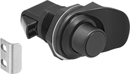
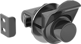
Push in the knob to open these latches.
To open latches with a pull tab, push the knob and pull the tab.
![]() For technical drawings and 3-D models, click on a part number.
For technical drawings and 3-D models, click on a part number.
Mounting | |||||||||||
|---|---|---|---|---|---|---|---|---|---|---|---|
| For Max. Door Thick. | Max. Latching Distance | For Through Hole Dia. | Dia. | Projection | Rear Projection | Latch Bolt Projection | Strike Plate Material | Fasteners Included | Screw Size | Each | |
Through-Hole Mount | |||||||||||
Black Plastic | |||||||||||
| 1/2" | 15/16" | 1" | 1 1/8" | 5/8" | 1 9/16" | 5/16" | Stainless Steel | No | No. 6 | 0000000 | 000000 |
Black Plastic with In-Line Pull Tab | |||||||||||
| 3/8" | 15/16" | 1" | 1 1/8" | 5/8" | 1 1/2" | 5/16" | Stainless Steel | No | No. 6 | 0000000 | 00000 |
Black Plastic with Perpendicular Pull Tab | |||||||||||
| 3/8" | 15/16" | 1" | 1 1/4" | 5/8" | 1 1/2" | 5/16" | Stainless Steel | No | No. 6 | 0000000 | 00000 |
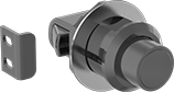
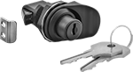
Push-to-Close Latches with Pop-Out Knob
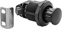
When not in use, push the knob in so it's flush and out of the way; it pops out with a touch. Latches open with a turn of the knob and can be secured with the knob in or out.
![]() For technical drawings and 3-D models, click on a part number.
For technical drawings and 3-D models, click on a part number.
Mounting | |||||||||||
|---|---|---|---|---|---|---|---|---|---|---|---|
| For Max. Door Thick. | Max. Latching Distance | For Through Hole Dia. | Dia. | Projection | Rear Projection | Latch Bolt Projection | Strike Plate Material | Fasteners Included | Screw Size | Each | |
Through-Hole Mount | |||||||||||
Black Plastic | |||||||||||
| 3/4" | 1 3/8" | 1 1/4" | 1 1/2" | 1/4" | 1 7/8" | 5/16" | Stainless Steel | No | No. 10 | 0000000 | 000000 |
Gray Plastic | |||||||||||
| 3/4" | 1 3/8" | 1 1/4" | 1 1/2" | 1/4" | 1 7/8" | 5/16" | Stainless Steel | No | No. 10 | 0000000 | 00000 |
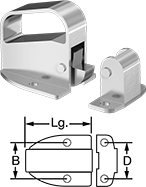
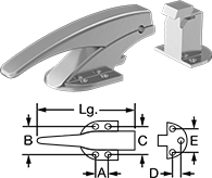
Vibration-Resistant Push-to-Close Latches with Handle
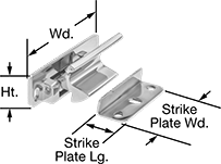
Their spring-loaded design withstands vibration, rattling, and shaking better than other face-mount push-to-close latches for a more secure hold. Mount these latches horizontally to the face of the door with the strike plate mounted on the frame.
![]() For technical drawings and 3-D models, click on a part number.
For technical drawings and 3-D models, click on a part number.
Strike Plate | ||||||||||
|---|---|---|---|---|---|---|---|---|---|---|
| Material | Appearance | Wd. | Ht. | Projection | Lg. | Wd. | Mounting Fasteners Included | Each | ||
| 4 | 316 Stainless Steel | Polished | 2 5/8" | 3/4" | 1" | 11/16" | 1 13/16" | Yes | 00000000 | 000000 |
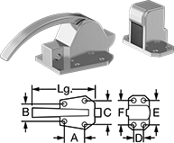
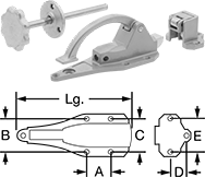
Pressure-Venting Push-to-Close Latches with Handle
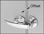
For use on spray booths and drying ovens, these latches automatically open when the internal pressure of the enclosure reaches a set level. They can also be manually opened by pulling on the handle. Mount latches horizontally to the face of the door with the strike plate mounted on the frame. To determine door mounting location, look at the outside face of the door: if the hinges are on the right, order a right-side latch; if the hinges are on the left, order a left-side latch.
Door offset is the space between the door face and the frame when the door is closed. Pressure release force is the amount of pressure an enclosed area can sustain before the latch opens. Adjust the catch to make the latch more or less sensitive to pressure. Styles 1 and 2 adjust with a slotted screwdriver.
![]() For technical drawings and 3-D models, click on a part number.
For technical drawings and 3-D models, click on a part number.
Mounting | ||||||||||
|---|---|---|---|---|---|---|---|---|---|---|
| For Door Offset | Pressure Release Force Range, lbs./sq. ft. | Lg. | Projection | Mounting Hole Ctr.-to-Ctr. (B) | Strike Plate Mounting Hole Ctr.-to-Ctr. (D) | Fasteners Included | Screw Size | Specifications Met | Each | |
316 Stainless Steel—Polished | ||||||||||
| 0" to 3/16" | 4 to 17 | 2 3/8" | 2 5/16" | 1 3/8" | 1 3/8" | No | 1/4" | FM Approved | 000000 | 0000000 |
Ring-Handle Push-to-Close Latches
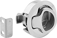
When released, the spring-loaded ring handle returns to its recessed position to stay out of the way. These latches open from the inside as well as the outside. From the outside, pull the recessed ring to unlatch. From the inside, slide the release tab on the back of the latch.
![]() For technical drawings and 3-D models, click on a part number.
For technical drawings and 3-D models, click on a part number.
Mounting | |||||||||||
|---|---|---|---|---|---|---|---|---|---|---|---|
| For Door Thick. | Max. Latching Distance | For Through Hole Dia. | Dia. | Projection | Rear Projection | Latch Bolt Projection | Strike Plate Material | Fasteners Included | Screw Size | Each | |
Through-Hole Mount | |||||||||||
Black Plastic | |||||||||||
| 1/8"-1/4" | 1" | 2" | 2 7/16" | 1/8" | 1 7/16" | 1/4" | Stainless Steel | No | No. 10 | 0000000 | 000000 |
| 5/16"-7/16" | 1" | 2" | 2 7/16" | 1/8" | 1 7/16" | 1/4" | Stainless Steel | No | No. 10 | 0000000 | 00000 |
| 1/2"-5/8" | 1" | 2" | 2 7/16" | 1/8" | 1 7/16" | 1/4" | Stainless Steel | No | No. 10 | 0000000 | 00000 |
| 11/16"-7/8" | 1" | 2" | 2 7/16" | 1/8" | 1 7/16" | 1/4" | Stainless Steel | No | No. 10 | 0000000 | 00000 |
316 Stainless Steel—Polished | |||||||||||
| 1/8"-1/4" | 1" | 2" | 2 7/16" | 1/8" | 1 7/16" | 1/4" | Stainless Steel | No | No. 10 | 0000000 | 00000 |
| 5/16"-7/16" | 1" | 2" | 2 7/16" | 1/8" | 1 7/16" | 1/4" | Stainless Steel | No | No. 10 | 0000000 | 00000 |
| 1/2"-5/8" | 1" | 2" | 2 7/16" | 1/8" | 1 7/16" | 1/4" | Stainless Steel | No | No. 10 | 0000000 | 00000 |
| 11/16"-7/8" | 1" | 2" | 2 7/16" | 1/8" | 1 7/16" | 1/4" | Stainless Steel | No | No. 10 | 0000000 | 00000 |
Paddle-Handle Push-to-Close Latches
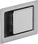
Also known as paddle latches, these are often used on electrical panels, cabinets, and lockers.
![]() For technical drawings and 3-D models, click on a part number.
For technical drawings and 3-D models, click on a part number.
For Cutout | ||||||||||
|---|---|---|---|---|---|---|---|---|---|---|
| For Max. Door Thick. | Max. Latching Distance | Ht. | Wd. | Ht. | Wd. | Rear Projection | Latch Bolt Projection | Mounting Fasteners Included | Each | |
304 Stainless Steel—Dull | ||||||||||
| 1/16" | 1/8" | 1" | 1 9/16" | 1 1/8" | 1 3/4" | 5/16" | 7/16" | Yes | 00000000 | 000000 |
| 1/16" | 3/16" | 1 7/16" | 1 7/8" | 1 7/8" | 2 1/4" | 1" | 1/2" | Yes | 00000000 | 00000 |
| 1/4" | 5/16" | 2 3/16" | 2 13/16" | 2 11/16" | 3 5/16" | 1 7/16" | 5/16" | Yes | 00000000 | 00000 |
| 3/8" | 15/32" | 3 1/4" | 4 1/4" | 4" | 5" | 1 15/16" | 7/16" | Yes | 00000000 | 00000 |
For Cutout | Mounting Hole | Mounting | ||||||||||||
|---|---|---|---|---|---|---|---|---|---|---|---|---|---|---|
| For Max. Door Thick. | Max. Latching Distance | Ht. | Wd. | Ht. | Wd. | Rear Projection | Latch Bolt Projection | Ctr.-to-Ctr. | Thread Size | Dp. | Fasteners Included | Screw Size | Each | |
300 Series Stainless Steel—Dull | ||||||||||||||
| 3/16" | 3/16" | 3 1/8" | 2" | 3 5/16" | 2 1/4" | 1/2" | 1/4" | 2" | 8-32 | 0.25" | No | No. 8 | 00000000 | 0000000 |
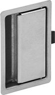
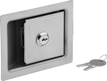
Paddle-Handle Keyed Push-to-Close Locks
Also known as paddle locks, these are often used on electrical panels, cabinets, and lockers. They're keyed alike, choose them if you need several locks that open with the same key.
![]() For technical drawings and 3-D models, click on a part number.
For technical drawings and 3-D models, click on a part number.
For Cutout | ||||||||||||
|---|---|---|---|---|---|---|---|---|---|---|---|---|
| For Max. Door Thick. | Max. Latching Distance | Ht. | Wd. | Ht. | Wd. | Rear Projection | Latch Bolt Projection | Mounting Fasteners Included | Key Number | No. of Keys Included | Each | |
304 Stainless Steel—Dull | ||||||||||||
| 3/8" | 1/2" | 3 1/4" | 4 1/4" | 4" | 5" | 1 15/16" | 7/16" | Yes | CH751 | 2 | 00000000 | 000000 |
Keyed Push-to-Close Locks with Push-Button-Release
To open, push in the knob and pull the tab. Choose these keyed alike locks if you need several that open with the same key.
![]() For technical drawings and 3-D models, click on a part number.
For technical drawings and 3-D models, click on a part number.
Mounting | |||||||||||||
|---|---|---|---|---|---|---|---|---|---|---|---|---|---|
| For Max. Door Thick. | Max. Latching Distance | For Through Hole Dia. | Dia. | Projection | Rear Projection | Latch Bolt Projection | Strike Plate Material | Fasteners Included | Screw Size | Key Number | Number of Keys Included | Each | |
Through-Hole Mount | |||||||||||||
Black Plastic | |||||||||||||
| 3/8" | 15/16" | 1" | 1 1/8" | 5/8" | 1 1/2" | 5/16" | Stainless Steel | No | No. 6 | CH751 | 2 | 0000000 | 000000 |
Padlockable Push-to-Close Latches with Handle
Mount these padlockable latches horizontally to the face of doors on refrigerators, ovens, and industrial enclosures with the strike plate mounted on the frame. Latches have an adjustable strike plate to compensate for changes in offset caused by sagging doors and worn or flattened gaskets. Door offset is the space between the door face and the frame when the door is closed.
![]() For technical drawings and 3-D models, click on a part number.
For technical drawings and 3-D models, click on a part number.
Mounting Hole Ctr.-to-Ctr. | Strike Plate Mounting Hole Ctr.-to-Ctr. | Mounting | ||||||||||||
|---|---|---|---|---|---|---|---|---|---|---|---|---|---|---|
| For Door Offset | Lg. | Projection | (A) | (B) | (C) | (D) | (E) | (F) | For Max. Padlock Shackle Dia. | Fasteners Included | Screw Size | Each | ||
304 Stainless Steel—Polished | ||||||||||||||
| 1 | 0" to 5/16" | 5 1/4" | 2" | 13/16" | 1 5/16" | 1 1/2" | 7/8" | 1 1/2" | __ | 1/4" | No | No. 8 | 000000 | 000000 |
| 1 | 5/8" to 1 1/4" | 5 1/4" | 2" | 13/16" | 1 5/16" | 1 1/2" | 7/8" | 1 1/2" | __ | 1/4" | No | No. 8 | 000000 | 00000 |
| 2 | 0" to 3/8" | 5 1/4" | 2 5/16" | 1 1/4" | 1 3/4" | 2 1/16" | 3/4" | 2 1/16" | 2 1/16" | 1/4" | No | No. 10 | 000000 | 000000 |
| 2 | 0" to 1/2" | 4 1/4" | 2 1/2" | 1 3/8" | 1 3/32" | 1 5/8" | 5/8" | 1 5/8" | 1 5/8" | 1/4" | No | No. 8 | 000000 | 000000 |
| 2 | 1/2" to 1 1/4" | 5 1/4" | 2 5/16" | 1 1/4" | 1 3/4" | 2 1/16" | 3/4" | 2 1/16" | 2 1/16" | 1/4" | No | No. 10 | 000000 | 000000 |
| 2 | 9/16" to 1 1/4" | 4 1/4" | 2 1/2" | 1 3/8" | 1 3/32" | 1 5/8" | 5/8" | 1 5/8" | 1 5/8" | 1/4" | No | No. 8 | 000000 | 000000 |
Padlockable Push-to-Close Latches with Emergency Release Handle

An emergency release handle offers a means of escape if a door closes with someone inside an enclosure. Mount these padlockable latches horizontally to the face of doors on refrigerators, ovens, and industrial enclosures with the strike plate mounted on the frame.
Latches have an adjustable strike plate to compensate for changes in offset caused by sagging doors and worn or flattened gaskets. Door offset is the space between the door face and the frame when the door is closed.
![]() For technical drawings and 3-D models, click on a part number.
For technical drawings and 3-D models, click on a part number.
Mounting Hole Ctr.-to-Ctr. | Strike Plate Mounting Hole Ctr.-to-Ctr. | Emergency Release | Mounting | ||||||||||||
|---|---|---|---|---|---|---|---|---|---|---|---|---|---|---|---|
| For Door Offset | Lg. | Projection | For Max. Padlock Shackle Dia. | (A) | (B) | (C) | (D) | (E) | Handle Material | Rod Material | Fasteners Included | Screw Size | Each | ||
304 Stainless Steel—Polished | |||||||||||||||
| 2 | 0" to 1/2" | 8" | 3 7/16" | 5/16" | 1 3/4" | 2 3/8" | 2 3/8" | 1 3/16" | 2 7/16" | Stainless Steel | Stainless Steel | No | 1/4" | 0000000 | 0000000 |
| 2 | 5/8" to 1 1/4" | 8" | 3 7/16" | 5/16" | 1 3/4" | 2 3/8" | 2 3/8" | 1 3/16" | 2 7/16" | Stainless Steel | Stainless Steel | No | 1/4" | 0000000 | 000000 |
| Replacement Steel Handle | 000000 | Each | 000000 |
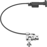
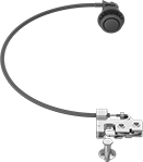
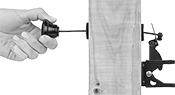
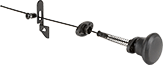
Self-Aligning Remote-Release Latches
Also known as rotary latches, these compensate for door misalignment when closing and then firmly grip the strike bolt for a secure hold. Operate the latches around corners and other obstructions—a flexible cable connects the latch and the handle. Maximum cumulative bend is the combination of individual bend angles the cable can withstand.
For T-handle release latches, pull on the handle to retract the spring-loaded latch.
For push-button release latches, push the button to retract the spring-loaded latch.
![]() For technical drawings and 3-D models, click on a part number.
For technical drawings and 3-D models, click on a part number.
Handle | Handle Plate | Strike Bolt | ||||||||||
|---|---|---|---|---|---|---|---|---|---|---|---|---|
| Cable Dia. | Max. Latch. Distance | Wd. | Mount. Hole Dia. | Lg. | Wd. | Mount. Hole Ctr.-to-Ctr. | Dia. | Lg. | Proj. | Max. Cumulative Bend | Each | |
3-ft. Cable Lg. | ||||||||||||
Left-Side Door Mount | ||||||||||||
| 1/4" | 5/8" | 7/8" | 3/16" | 2 3/16" | 1 3/4" | 1", 1 9/16" | 3/8" | 1 1/2" | 1" | 720° | 0000000 | 000000 |
Right-Side Door Mount | ||||||||||||
| 1/4" | 5/8" | 7/8" | 3/16" | 2 3/16" | 1 3/4" | 1", 1 9/16" | 3/8" | 1 1/2" | 1" | 720° | 0000000 | 00000 |
5-ft. Cable Lg. | ||||||||||||
Left-Side Door Mount | ||||||||||||
| 1/4" | 5/8" | 7/8" | 3/16" | 2 3/16" | 1 3/4" | 1", 1 9/16" | 3/8" | 1 1/2" | 1" | 720° | 0000000 | 00000 |
Right-Side Door Mount | ||||||||||||
| 1/4" | 5/8" | 7/8" | 3/16" | 2 3/16" | 1 3/4" | 1", 1 9/16" | 3/8" | 1 1/2" | 1" | 720° | 0000000 | 00000 |
Keyed Locks for Sliding Gates
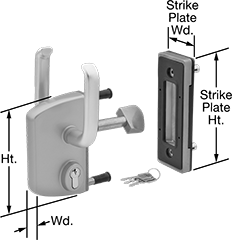
In addition to sliding gates, this lock is for use on cantilever and fixed-roller gates. With a key-locking mechanism, it provides more security than other gate locks. Choose this lock if you need locks that each open with a different key.
![]() For technical drawings and 3-D models, click on a part number.
For technical drawings and 3-D models, click on a part number.
Strike Plate | |||||||||
|---|---|---|---|---|---|---|---|---|---|
| Material | For Through Hole Dia. | Ht. | Wd. | Ht. | Wd. | Mounting Fasteners Included | No. of Keys Included | Each | |
Through-Hole Mount | |||||||||
| Gray Powder-Coated 300 Series Stainless Steel | 7/8" | 6 5/16" | 3 3/4" | 7 11/16" | 2 3/4" | Yes | 3 | 0000000 | 0000000 |
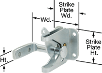
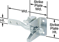
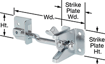
Padlockable Gate Latches
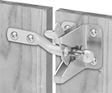
Push to close and pull up on the latch arm to open these padlockable latches. They are self-latching, meaning that a catch grabs and holds the strike plate to keep doors shut. All of these latches are reversible for left or right-hand mounting. The arm has a hole to add a pull cord or chain.
Fasten surface-mounted latches to the front of the gate and post, so the two pieces are parallel.
Latches with 90° bolt are for gates that overlap the post when closed. Latches with straight bolt are for gates that close flush with the post.
Mount latches with a fixed bolt directly to the gate. These latches are quick to install and require less mounting space than adjustable-bolt latches, but are difficult to adjust once installed. Latches with an adjustable bolt have multiple mounting holes for the bolt, so you can change its alignment without moving the whole latch. Adjustable latches with a button are the easiest to adjust—depress a button to move the bolt instead of unscrewing it from the mounting plate.
The smooth finish on powder-coated steel latches protects the underlying steel from rust in wet environments. If the coating is chipped or scratched, the steel will rust.
Stainless steel latches are the most corrosion-resistant, and will hold up to water and chemicals.
Attach pull cords to a hole on the arm to open an unlocked gate from either side of the fence.
![]() For technical drawings and 3-D models, click on a part number.
For technical drawings and 3-D models, click on a part number.
Strike Plate | Mounting | ||||||||||||
|---|---|---|---|---|---|---|---|---|---|---|---|---|---|
| Material | Appearance | Ht. | Wd. | Projection | Ht. | Wd. | Pull Cord Hole Dia. | For Max. Padlock Shackle Dia. | Fasteners Included | Screw Size | Adjustable Bolt Type | Each | |
Fixed 90° Bolt | |||||||||||||
| 304 Stainless Steel | Dull | 1/2" | 4" | 2 3/4" | 1 3/4" | 1 1/2" | 3/16" | 5/16" | No | No. 8 | __ | 0000000 | 000000 |
Fixed Straight Bolt | |||||||||||||
| Black Powder-Coated 302 Stainless Steel | __ | 9/16" | 4 1/2" | 2 3/16" | 1 11/16" | 1 3/8" | 3/16" | 5/16" | __ | __ | __ | 0000000 | 00000 |
| 304 Stainless Steel | Dull | 1/2" | 4 3/4" | 2 3/4" | 1 3/4" | 1 1/2" | 3/16" | 5/16" | No | No. 8 | __ | 0000000 | 00000 |
Adjustable Straight Bolt | |||||||||||||
| 302 Stainless Steel | Dull | 1 13/16" | 4 1/8" | 2 1/8" | 1 13/16" | 1 3/8" | 3/16" | 5/16" | __ | __ | Button | 0000000 | 00000 |
| Lg. | Mounting Fasteners Included | Each | |
| 10 3/4" | Yes | 0000000 | 000000 |