


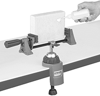
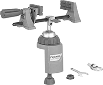
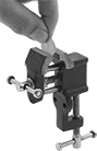
Bench Vises for Dremel
 |  |  |
Swivel Base | Swivel Base Removable Clamp | Swivel Base |
Jaw | Overall | |||||||||||||||||
|---|---|---|---|---|---|---|---|---|---|---|---|---|---|---|---|---|---|---|
Wd. | Max. Opening | Material | Texture | Throat Dp. | Lg. | Wd. | Ht. | Wt., lb. | For Max. Mounting Surface Thk. | Body Material | Mount Type | For Mfr. Model No. | Features | Includes | Each | |||
360° Swivel Base | ||||||||||||||||||
| 7 1/2" | 7" | Rubber | Grooved | 2 1/4" | 13" | 4 1/4" | 13" | 2.7 | 2 1/2" | Plastic | Clamp On | 100, 100-N/7, 200, 285, 300, 395, 400, 800, 3000, 3000-1/24, 4000, 4000-2/30, 4200, 8100-N/21, 8200, 8220, 8220-1/28 | Removable Clamp | Tool Holder Ring | 4729N11 | 000000 | ||
Heavy Duty Positioning Arms
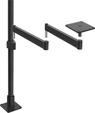 | 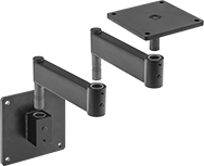 |
Arm Built with Floor- and Bench-Mount Pole Base, Pole, Pole-to-Pin Adapter, Two Rigid Connectors, and Pivoting Mounting Plate | Arm Built with Wall-Mount Pin Base, Two Rigid Connectors, and Pivoting Mounting Plate |
 |  |
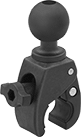
Clamp-On Adapter with Quick-Adjust Lever | Clamp-On Adapter |
Lg. | Wd. | Ht. | For Pin Dia. | For Pole Dia. | Max. Load Cap., lb. | Material | Color | Each | |||
|---|---|---|---|---|---|---|---|---|---|---|---|
Clamp-On Adapter | |||||||||||
| 4 5/8" | 2 15/16" | 2 3/8" | 7/8" | 2" | 100 | Anodized Aluminum | Black | 5164T941 | 000000 | ||
| 4 5/8" | 2 15/16" | 2 5/8" | 7/8" | 1 1/2" | 100 | Anodized Aluminum | Black | 5164T41 | 000000 | ||
Clamp-On Adapter with Quick-Adjust Lever | |||||||||||
| 7 13/16" | 3 1/8" | 3 7/16" | 7/8" | 2" | 100 | Powder-Coated Steel | Black | 5164T42 | 00000 | ||
Ball-Grip Positioning Arms
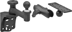 |
Arm Built with Rotating Complete Arm with Ball, Rigid Connector, and Universal Mounting Plate |
 | 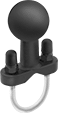 | 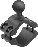 | 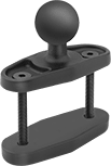 |
Clamp-On Pipe-Mount Bases, Style A | Clamp-On Pipe-Mount Bases, Style B | Clamp-On Pipe-Mount Bases, Style C | Clamp-On Rectangular Bar Mount Bases, Style D |
| | |
Style A | Style B | Style C |
Base | |||||||||||||
|---|---|---|---|---|---|---|---|---|---|---|---|---|---|
Style | Clamping Distance Range | Ht. | Ball Dia. | Max. Load Cap., lb. | Material | Ball Material | Color | Lg. | Wd. | Each | |||
Rotate, Tilt, Side to Side, In/Out | |||||||||||||
| A | 5/8" to 1 1/8" | 4 3/16" | 1" | 1 | Plastic | Rubber | Black | — | 1 7/16" | 5031T104 | 000000 | ||
| A | 5/8" to 1 1/8" | 4 1/4" | 1 1/2" | 3 | Plastic | Rubber | Black | — | 1 7/16" | 5031T567 | 00000 | ||
| B | 1" to 1 1/4" | 3" | 1 1/2" | 3 | Powder-Coated Aluminum | Rubber | Black | 2 3/8" | 7/8" | 5031T38 | 00000 | ||
| C | 2" to 2 1/2" | 3 1/2" | 1 1/2" | 3 | Powder-Coated Aluminum | Rubber | Black | 4" | 2 1/8" | 5031T131 | 00000 | ||
|
Style D |
Base | |||||||||||||
|---|---|---|---|---|---|---|---|---|---|---|---|---|---|
Style | Clamping Distance Range | Ht. | Ball Dia. | Max. Load Cap., lb. | Material | Ball Material | Color | Lg. | Wd. | Each | |||
Rotate, Tilt, Side to Side, In/Out | |||||||||||||
| D | 0" to 2 1/2" | 2 1/2" | 1 1/2" | 3 | Powder-Coated Aluminum | Rubber | Black | 3 1/8" | 1 1/4" | 5031T28 | 000000 | ||
| D | 0" to 3" | 4 11/16" | 1" | 1 | Powder-Coated Aluminum | Rubber | Black | 4 7/8" | 1 13/16" | 5031T106 | 00000 | ||
| D | 0" to 4" | 5 7/16" | 1 1/2" | 3 | Powder-Coated Aluminum | Rubber | Black | 5 7/8" | 2 9/16" | 5031T112 | 00000 | ||
| D | 0" to 4" | 8 5/16" | 2 1/4" | 6 | Powder-Coated Aluminum | Rubber | Black | 5 13/16" | 2 9/16" | 5031T115 | 00000 | ||
Leveling Jacks with Wheel
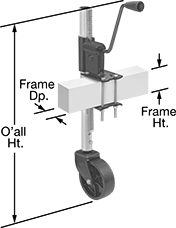 | 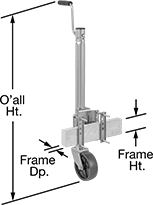 | 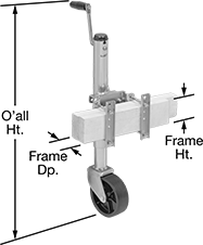 |
Style A | Style B | Style C |
For Frame | ||||||||||||||
|---|---|---|---|---|---|---|---|---|---|---|---|---|---|---|
Style | Weight Capacity | Ht. | Max. Lift | Overall Ht. | Ht. | Dp. | Handle Lg. | Body Material | Mounting Fasteners Included | Wheel Material | Each | |||
Clamp On Side Mount | ||||||||||||||
| A | 1/4 ton/750 lb. | 7 1/2" to 23 1/2" | 16" | 27 7/8" | 0" to 5" | 1 7/8" to 2 7/8" | 5 1/2" | Steel | Yes | Plastic | 2958T6 | 0000000 | ||
| B | 1/2 ton/1,000 lb. | 10 13/16" to 25 1/2" | 14 11/16" | 33 7/8" | 3" to 5" | 2" to 3" | 6 1/8" | Steel | Yes | Plastic | 8792T31 | 000000 | ||
Clamp On Side Mount with Locking Pin | ||||||||||||||
| C | 1/2 ton/1,200 lb. | 12 1/2" to 22 1/2" | 10" | 28 1/8" | 2" to 4" | 1 1/2" to 3" | 6" | Steel | Yes | Plastic | 8792T44 | 000000 | ||
| C | 3/4 ton/1,500 lb. | 12 7/8" to 22 7/8" | 10" | 31 5/8" | 3" to 5" | 2" to 3" | 6 1/8" | Steel | Yes | Plastic | 8792T32 | 000000 | ||
Flashlight Mounts
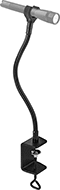 |
Clamp On |
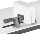
Miniature Clamp-On Bench Vises
 | 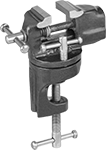 |
Fixed Base | Swivel Base |
Jaw | Overall | Mounting Holes | |||||||||||||||||
|---|---|---|---|---|---|---|---|---|---|---|---|---|---|---|---|---|---|---|---|
Wd. | Max. Opening | Material | Texture | Replaceable | Throat Dp. | Lg. | Wd. | Ht. | Wt., lb. | For Max. Mounting Surface Thk. | Body Material | Mount Type | Mounting Fasteners Included | No. of | Dia. | Each | |||
Fixed Base | |||||||||||||||||||
| 1 3/32" | 1" | Iron | Smooth | No | 5/16" | 4 1/2" | 1 1/4" | 3" | 1 | 1" | Iron | Bolt On, Clamp On | No | 2 | 3/16" | 6015A33 | 00000 | ||
| 1 3/4" | 1 1/4" | Steel | Smooth | No | 3/4" | 3 1/2" | 1 3/4" | 4 1/4" | 1.3 | 1 1/2" | Iron | Clamp On | — | — | — | 6015A34 | 00000 | ||
| 2 3/16" | 1 1/4" | Steel | Smooth | No | 3/4" | 3 1/2" | 2 1/4" | 4 1/4" | 1.4 | 1 1/2" | Iron | Clamp On | — | — | — | 6015A35 | 00000 | ||
180° Swivel Base | |||||||||||||||||||
| 1 1/2" | 1" | Steel | Smooth | No | 3/4" | 4" | 2 1/4" | 4 1/4" | 1.7 | 1 1/8" | Steel | Clamp On | — | — | — | 6015A36 | 00000 | ||
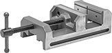
Any-Orientation Drill-Press Vises
 |
Jaw | Body | |||||||||||||
|---|---|---|---|---|---|---|---|---|---|---|---|---|---|---|
Wd. | Ht. | Max. Opening | Material | Texture | Replaceable | Overall Ht. | Lg. | Material | Mount Type | Features | Each | |||
Fixed Base | ||||||||||||||
| 1 1/2" | 1" | 1 1/2" | Steel | Smooth, Grooved | Yes | 1 7/8" | 5 1/8" | Iron | Clamp On | Open Base | 5226A2 | 000000 | ||
| 2 7/16" | 1 1/2" | 3" | Steel | Smooth, Grooved | Yes | 2 5/8" | 7 1/2" | Iron | Clamp On | Open Base | 5226A3 | 000000 | ||
| 3" | 1 3/4" | 3" | Steel | Smooth | Yes | 3" | 9" | Iron | Clamp On | Open Base | 5226A7 | 000000 | ||
| 4" | 1 3/4" | 4" | Steel | Smooth, Grooved | Yes | 3 1/4" | 10 3/4" | Iron | Clamp On | Open Base | 5226A6 | 000000 | ||
| 6" | 2" | 6" | Steel | Smooth, Grooved | Yes | 3 1/2" | 11 3/8" | Iron | Clamp On | Open Base | 5226A75 | 000000 | ||
Clamp-On Bench Vises
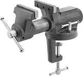 |
Swivel Base |
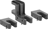
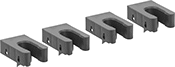
Vises | Replacement Flat Jaws | ||||||||||||||||||
|---|---|---|---|---|---|---|---|---|---|---|---|---|---|---|---|---|---|---|---|
Jaw | Overall | ||||||||||||||||||
Wd. | Max. Opening | Material | Texture | Replaceable | Throat Dp. | Lg. | Wd. | Ht. | Wt., lb. | For Max. Mounting Surface Thk. | Body Material | Mount Type | Features | Each | Each | ||||
45° Swivel Base | |||||||||||||||||||
| 2 1/2" | 2 1/8" | Steel | Grooved | Yes | 1 3/4" | 10" | 10 1/4" | 5 1/2" | 11 | 3" | Iron | Clamp On | Anvil | 4985A1 | 0000000 | 8467A91 | 000000 | ||
| 4" | 2 1/4" | Steel | Grooved | Yes | 2" | 10" | 10 1/4" | 5 1/2" | 18 | 3" | Iron | Clamp On | Anvil | 4985A2 | 000000 | 8467A92 | 00000 | ||
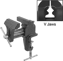 | 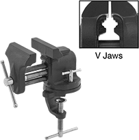 |
Fixed Base | Swivel Base |
Flat Jaw | Overall | Mounting Holes | |||||||||||||||||||
|---|---|---|---|---|---|---|---|---|---|---|---|---|---|---|---|---|---|---|---|---|---|
Wd. | Max. Opening | Material | Texture | V Jaw For Dia. | Throat Dp. | Lg. | Wd. | Ht. | Wt., lb. | For Max. Mounting Surface Thk. | Body Material | Mount Type | Mounting Fasteners Included | No. of | Flat Jaw Dia. | V Jaw Dia. | Features | Each | |||
Fixed Base | |||||||||||||||||||||
| 3" | 2 1/2" | Iron | Smooth | 3/8" to 2" | 2 5/8" | 6" | 6" | 6" | 4 | 2" | Iron | Bolt On, Clamp On | No | 2 | 3/16" | — | Anvil | 5312A2 | 000000 | ||
360° Swivel Base | |||||||||||||||||||||
| 3" | 2 1/2" | Iron | Smooth | 3/8" to 2" | 2 5/8" | 6" | 6" | 6" | 6 | 1 7/8" | Iron | Bolt On, Clamp On | No | 2 | 1/4" | 5/16" | Anvil | 5312A3 | 000000 | ||
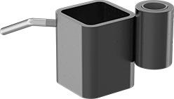
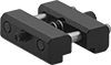
Pipettor Holders
 |  |
Clamp On | Additional Extenders (Sold Separately) |
Ultra-Precision Machine Vises
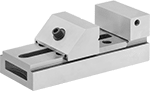 |
Jaw | Body | Mounting Holes | ||||||||||||||||
|---|---|---|---|---|---|---|---|---|---|---|---|---|---|---|---|---|---|---|
Wd. | Ht. | Max. Opening | Material | Texture | Replaceable | Parallel Tolerance | Overall Ht. | Lg. | Material | Base/Bed Parallel Tolerance | Mount Type | Mounting Fasteners Included | No. of | Dia. | Each | |||
Fixed Base | ||||||||||||||||||
| 3" | 1 5/16" | 4 3/4" | Steel | Smooth, Grooved | No | 0.0002" | 2 5/8" | 7 1/2" | Steel | 0.0002" | Bolt On, Clamp On | No | 4 | 5/16" | 5218A54 | 000000000 | ||
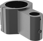
Clamp-On Machine Vise Stops
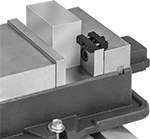 |  |
For Jaw Thk. | Lg. | Wd. | Ht. | Material | Each | ||
|---|---|---|---|---|---|---|---|
| 1/2" to 1" | 1 7/16" | 1" | 1/2" | Steel | 51985A67 | 000000 |
Vehicle-Mount Ladder Racks
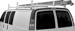 | 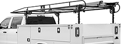 |
Style A Shown Mounted with a Ladder | Style C Shown Mounted with a Ladder |
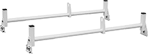 | 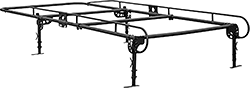 |
Style A | Style C |
Racks | Crossbars | ||||||||||||||
|---|---|---|---|---|---|---|---|---|---|---|---|---|---|---|---|
Style | Lg. | Wd. | Ht. | Overall Wt. Cap., lb. | Material | Color | Mount Type | Assembly | Includes | Each | Each | ||||
For Cargo Van | |||||||||||||||
| A | — | 41" to 72" | — | 600 | Powder-Coated Steel | White | Clamp On | Unassembled | 2 Crossbars, 2 Clamps, Mounting Hardware | 8929N112 | 0000000 | 8929N113 | 000000 | ||
For Pickup Truck | |||||||||||||||
| C | 138" | 56" | 36" | 1,000 | Powder-Coated Steel | Black | Clamp On, Bolt On | Unassembled | 3 Crossbars, Mounting Hardware | 8929N115 | 000000 | ——— | 0 | ||
