


Filter by
Body Shape
Maximum Holding Torque
Number of Shafts
Mounting Position
Full Step Increment
Face Shape

Number of Wire Leads
Enclosure Material
Voltage
Motor Type
Direction of Operation


Component
U.S.–Mexico–Canada Agreement (USMCA) Qualifying
DFARS Specialty Metals
Export Control Classification Number (ECCN)
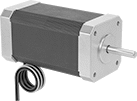
Clean Room Stepper Motors
Motors
 |
 |  |
Maximum Holding Torque—Holding torque is the force needed to move the shaft out of position when it is stationary. When the shaft is in motion, torque generally decreases as speed increases. Use a torque-speed curve to confirm which motor will work for your application. Click on a part number and select “Product Detail” to view the curve for a motor.
Full Step Increment—Full step increment is the rotation of the shaft from one position to the next. A smaller full step increment means the rotor has more teeth, producing smoother and more precise motion. 1.8° is considered standard.
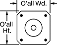
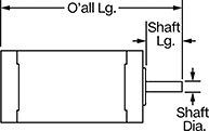
Overall | Shaft | Temp. Range, ° F | ||||||||||||||||||
|---|---|---|---|---|---|---|---|---|---|---|---|---|---|---|---|---|---|---|---|---|
Max. Holding Torque, in·ozf | Max. Rotation Speed, rpm | Max. Current per Phase, amp | Full Step Increment | Stepper Motor Polarity | No. of Wire Leads | Lg. | Wd. | Ht. | Dia., mm | Lg., mm | Type | No. of Shafts | Vacuum Rating, Torr | Min. | Max. | Clean Room Std. | Each | |||
Square Body | ||||||||||||||||||||
NEMA 11 Frame Size | ||||||||||||||||||||
| 10 | 3,250 | 0.67 | 1.8° | Bipolar | 4 | 2.1" | 1.1" | 1.1" | 5 | 18 | Solid | 1 | 1× 10^-7 | 0 | 120 | ISO Class 1 | 4799N11 | 000000000 | ||
| 19.5 | 1,550 | 0.67 | 1.8° | Bipolar | 4 | 2.8" | 1.1" | 1.1" | 5 | 18 | Solid | 1 | 1× 10^-7 | 0 | 120 | ISO Class 1 | 4799N12 | 00000000 | ||
NEMA 17 Frame Size | ||||||||||||||||||||
| 85.4 | 850 | 1.05 | 1.8° | Bipolar | 4 | 2.9" | 1.7" | 1.7" | 5 | 22 | Solid | 1 | 1× 10^-7 | 0 | 120 | ISO Class 1 | 4799N13 | 00000000 | ||
| 115.1 | 1,150 | 2 | 1.8° | Bipolar | 4 | 3.3" | 1.7" | 1.7" | 5 | 22 | Solid | 1 | 1× 10^-7 | 0 | 120 | ISO Class 1 | 4799N14 | 00000000 | ||
NEMA 23 Frame Size | ||||||||||||||||||||
| 181 | 1,300 | 2.8 | 1.8° | Bipolar | 4 | 3.1" | 2.3" | 2.3" | 6 | 21 | D-Profile | 1 | 1× 10^-7 | 0 | 120 | ISO Class 1 | 4799N15 | 00000000 | ||
| 237 | 2,000 | 4 | 1.8° | Bipolar | 4 | 4" | 2.3" | 2.3" | 6 | 21 | D-Profile | 1 | 1× 10^-7 | 0 | 120 | ISO Class 1 | 4799N16 | 00000000 | ||
Clean Room Electric Positioning Slides
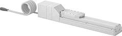 |
Slide |
 |
Controller (Included) |
Prevent dust from circulating while precisely positioning parts for drilling, fastening, assembly, and measuring. These slides have a built-in vacuum port to remove fine particles that could damage electronics or contaminate batches in clean rooms. Because they have an integrated stepper motor with an included controller, you can adjust the speed, timing, and positioning. At -0.02 to 0.02 mm, these slides have a repeatability thinner than a single sheet of paper, so the carriage hits the same spot every time. Unlike air-powered actuators, they’ll hold their position even if power fails. They’re also more energy efficient.
Dynamic load capacity is the maximum load slides can move. If you increase the speed, the dynamic load capacity decreases. Use a load-speed chart to confirm which slides will work for your application. Click on a part number and select "Product Detail" to view the chart.
814.5 mm Overall Length—814.5 mm lg. slides come pre-programmed with no extra software required.
Maximum Speed—Maximum speed is how fast the slide will move under no-load conditions. If you increase the load, the slide speed will decrease.
Travel Distance per Full Step—Travel distance per full step determines the control you have over the slide’s positioning. The smaller the measurement, the finer positioning control you have.
Travel Distance per Turn—Travel distance per turn, also known as screw lead, is how far the carriage moves with one rotation of the ball screw.
Cords—Use a USB cord (sold separately) and free downloadable software to program the controller for slides that are not 814.5 mm long.
Slides | Cords | ||||||||||||||||||||
|---|---|---|---|---|---|---|---|---|---|---|---|---|---|---|---|---|---|---|---|---|---|
Dynamic Load Cap., lb. | Travel Distance per, mm | Overall, mm | Carriage | ||||||||||||||||||
Horiz. | Vert. | Max. Speed, mm/s | Full Step | Turn | Repeatability, mm | Lg. | Wd. | Ht. | Lg., mm | Wd., mm | Bearing Type | Base Material | Full Load Current, amp | Voltage, V DC | Clean Room Std. | Each | Each | ||||
200 mm Stroke Length | |||||||||||||||||||||
| 110 | 44 | 250 | 0.08 | 8 | -0.02 to 0.02 | 541 | 70 | 84 | 122 | 60 | Ball | Aluminum | 5 | 24 | Fed. Std. Class 10, ISO Class 4 | 6833N32 | 000000000 | 6449N17 | 0000000 | ||
| 143 | 50 | 250 | 0.1 | 10 | -0.02 to 0.02 | 614.5 | 90 | 85.5 | 170 | 74 | Ball | Aluminum | 5 | 24 | Fed. Std. Class 10, ISO Class 4 | 6833N42 | 00000000 | 6449N17 | 000000 | ||
300 mm Stroke Length | |||||||||||||||||||||
| 110 | 44 | 250 | 0.08 | 8 | -0.02 to 0.02 | 641 | 70 | 84 | 122 | 60 | Ball | Aluminum | 5 | 24 | Fed. Std. Class 10, ISO Class 4 | 6833N33 | 00000000 | 6449N17 | 000000 | ||
400 mm Stroke Length | |||||||||||||||||||||
| 110 | 44 | 250 | 0.08 | 8 | -0.02 to 0.02 | 741 | 70 | 84 | 122 | 60 | Ball | Aluminum | 5 | 24 | Fed. Std. Class 10, ISO Class 4 | 6833N34 | 00000000 | 6449N17 | 000000 | ||
| 143 | 50 | 250 | 0.1 | 10 | -0.02 to 0.02 | 814.5 | 90 | 85.5 | 170 | 74 | Ball | Aluminum | 5 | 24 | Fed. Std. Class 10, ISO Class 4 | 6833N24 | 00000000 | ——— | 0 | ||
600 mm Stroke Length | |||||||||||||||||||||
| 143 | 50 | 250 | 0.1 | 10 | -0.02 to 0.02 | 1,014.5 | 90 | 85.5 | 170 | 74 | Ball | Aluminum | 5 | 24 | Fed. Std. Class 10, ISO Class 4 | 6833N46 | 00000000 | 6449N17 | 000000 | ||
800 mm Stroke Length | |||||||||||||||||||||
| 143 | 50 | 250 | 0.1 | 10 | -0.02 to 0.02 | 1,214.5 | 90 | 85.5 | 170 | 74 | Ball | Aluminum | 5 | 24 | Fed. Std. Class 10, ISO Class 4 | 6833N48 | 00000000 | 6449N17 | 000000 | ||
