Filter by
Motor Frame Size
Shaft Diameter
Body Shape
Maximum Holding Torque
Overall Width
Number of Shafts
Direction of Operation
Full Step Increment
Mounting Position
Motor Type
Number of Wire Leads
Thrust Load Capacity
Face Shape
Voltage
RoHS
Export Control Classification Number (ECCN)
REACH
DFARS Specialty Metals
U.S.–Mexico–Canada Agreement (USMCA) Qualifying
Stepper Motors
Motors
Overall | Shaft | Temp. Range, ° F | |||||||||||||||||||||||||||||||||||||||||||||||||||||||||||||||||||||||||||||||||||||||||||||||||
|---|---|---|---|---|---|---|---|---|---|---|---|---|---|---|---|---|---|---|---|---|---|---|---|---|---|---|---|---|---|---|---|---|---|---|---|---|---|---|---|---|---|---|---|---|---|---|---|---|---|---|---|---|---|---|---|---|---|---|---|---|---|---|---|---|---|---|---|---|---|---|---|---|---|---|---|---|---|---|---|---|---|---|---|---|---|---|---|---|---|---|---|---|---|---|---|---|---|---|---|
Max. Holding Torque, in·ozf | Max. Rotation Speed, rpm | Max. Current per Phase, amp | Full Step Increment | Stepper Motor Polarity | No. of Wire Leads | Lg. | Wd. | Ht. | Dia., mm | Lg., mm | Ctr.-to-Base Lg. | Type | No. of Shafts | Min. | Max. | Each | |||||||||||||||||||||||||||||||||||||||||||||||||||||||||||||||||||||||||||||||||||
Square Body | |||||||||||||||||||||||||||||||||||||||||||||||||||||||||||||||||||||||||||||||||||||||||||||||||||
NEMA 11 Frame Size | |||||||||||||||||||||||||||||||||||||||||||||||||||||||||||||||||||||||||||||||||||||||||||||||||||
| 8.5 | 3,300 | 0.67 | 1.8° | Bipolar | 4 | 2.1" | 1.1" | 1.1" | 5 | 18 | 0.56" | Solid | 1 | 0 | 120 | 0000000 | 0000000 | ||||||||||||||||||||||||||||||||||||||||||||||||||||||||||||||||||||||||||||||||||
| 14 | 2,475 | 0.67 | 1.8° | Bipolar | 4 | 2.6" | 1.1" | 1.1" | 5 | 18 | 0.56" | Solid | 1 | 0 | 120 | 00000000 | 000000 | ||||||||||||||||||||||||||||||||||||||||||||||||||||||||||||||||||||||||||||||||||
| 17 | 2,475 | 0.67 | 1.8° | Bipolar | 4 | 2.8" | 1.1" | 1.1" | 5 | 18 | 0.56" | Solid | 1 | 0 | 120 | 00000000 | 000000 | ||||||||||||||||||||||||||||||||||||||||||||||||||||||||||||||||||||||||||||||||||
Clean Room Stepper Motors
Motors
Overall | Shaft | Temp. Range, ° F | |||||||||||||||||||||||||||||||||||||||||||||||||||||||||||||||||||||||||||||||||||||||||||||||||
|---|---|---|---|---|---|---|---|---|---|---|---|---|---|---|---|---|---|---|---|---|---|---|---|---|---|---|---|---|---|---|---|---|---|---|---|---|---|---|---|---|---|---|---|---|---|---|---|---|---|---|---|---|---|---|---|---|---|---|---|---|---|---|---|---|---|---|---|---|---|---|---|---|---|---|---|---|---|---|---|---|---|---|---|---|---|---|---|---|---|---|---|---|---|---|---|---|---|---|---|
Max. Holding Torque, in·ozf | Max. Rotation Speed, rpm | Max. Current per Phase, amp | Full Step Increment | Stepper Motor Polarity | No. of Wire Leads | Lg. | Wd. | Ht. | Dia., mm | Lg., mm | Type | No. of Shafts | Vacuum Rating, Torr | Min. | Max. | Clean Room Std. | Each | ||||||||||||||||||||||||||||||||||||||||||||||||||||||||||||||||||||||||||||||||||
Square Body | |||||||||||||||||||||||||||||||||||||||||||||||||||||||||||||||||||||||||||||||||||||||||||||||||||
NEMA 11 Frame Size | |||||||||||||||||||||||||||||||||||||||||||||||||||||||||||||||||||||||||||||||||||||||||||||||||||
| 10 | 3,250 | 0.67 | 1.8° | Bipolar | 4 | 2.1" | 1.1" | 1.1" | 5 | 18 | Solid | 1 | 1× 10^-7 | 0 | 120 | ISO Class 1 | 0000000 | 000000000 | |||||||||||||||||||||||||||||||||||||||||||||||||||||||||||||||||||||||||||||||||
| 19.5 | 1,550 | 0.67 | 1.8° | Bipolar | 4 | 2.8" | 1.1" | 1.1" | 5 | 18 | Solid | 1 | 1× 10^-7 | 0 | 120 | ISO Class 1 | 0000000 | 00000000 | |||||||||||||||||||||||||||||||||||||||||||||||||||||||||||||||||||||||||||||||||
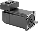
Stepper Servomotors with Integrated Drive
 |
Overall | Shaft | No. of Inputs/Outputs | |||||||||||||||||||||||||||||||||||||||||||||||||||||||||||||||||||||||||||||||||||||||||||||||||
|---|---|---|---|---|---|---|---|---|---|---|---|---|---|---|---|---|---|---|---|---|---|---|---|---|---|---|---|---|---|---|---|---|---|---|---|---|---|---|---|---|---|---|---|---|---|---|---|---|---|---|---|---|---|---|---|---|---|---|---|---|---|---|---|---|---|---|---|---|---|---|---|---|---|---|---|---|---|---|---|---|---|---|---|---|---|---|---|---|---|---|---|---|---|---|---|---|---|---|---|
Max. Holding Torque, in·ozf | Max. Rotation Speed, rpm | Voltage, V DC | Current, amp | Step Resolution | Full Step Increment | Lg. | Wd. | Ht. | Dia., mm | Lg., mm | Ctr.-to-Base Lg. | Communication Protocol | Digital Inputs | Digital Outputs | Enclosure Rating | Each | |||||||||||||||||||||||||||||||||||||||||||||||||||||||||||||||||||||||||||||||||||
NEMA 11 Frame Size | |||||||||||||||||||||||||||||||||||||||||||||||||||||||||||||||||||||||||||||||||||||||||||||||||||
| 9.2 | 3,000 | 15 to 30 | 0.9 | 1 to 1/256 | 1.8° | 2.7" | 1.1" | 1.5" | 5 | 13 | 0.57" | Modbus RTU | 4 | 2 | IP20 | 0000000 | 0000000 | ||||||||||||||||||||||||||||||||||||||||||||||||||||||||||||||||||||||||||||||||||
| 11.3 | 3,000 | 15 to 30 | 1 | 1 to 1/256 | 1.8° | 3" | 1.1" | 1.5" | 5 | 13 | 0.57" | Modbus RTU | 4 | 2 | IP20 | 0000000 | 000000 | ||||||||||||||||||||||||||||||||||||||||||||||||||||||||||||||||||||||||||||||||||
| 17.7 | 3,000 | 15 to 30 | 1 | 1 to 1/256 | 1.8° | 3.5" | 1.1" | 1.5" | 5 | 13 | 0.57" | Modbus RTU | 4 | 2 | IP20 | 0000000 | 000000 | ||||||||||||||||||||||||||||||||||||||||||||||||||||||||||||||||||||||||||||||||||
