Filter by
Motor Frame Size
Maximum Holding Torque
Body Shape
Mounting Position
Component
Shaft Type
Voltage
Number of Shafts
Face Shape
Direction of Operation
Overall Width
Number of Wire Leads
Full Step Increment
Thrust Load Capacity
DFARS Specialty Metals
Export Control Classification Number (ECCN)
REACH
RoHS
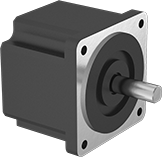
Stepper Motors
Motors
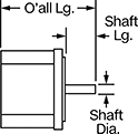
Overall | Shaft | Temp. Range, ° F | |||||||||||||||||||||||||||||||||||||||||||||||||||||||||||||||||||||||||||||||||||||||||||||||||
|---|---|---|---|---|---|---|---|---|---|---|---|---|---|---|---|---|---|---|---|---|---|---|---|---|---|---|---|---|---|---|---|---|---|---|---|---|---|---|---|---|---|---|---|---|---|---|---|---|---|---|---|---|---|---|---|---|---|---|---|---|---|---|---|---|---|---|---|---|---|---|---|---|---|---|---|---|---|---|---|---|---|---|---|---|---|---|---|---|---|---|---|---|---|---|---|---|---|---|---|
Max. Holding Torque, in·ozf | Max. Rotation Speed, rpm | Max. Current per Phase, amp | Full Step Increment | Stepper Motor Polarity | No. of Wire Leads | Lg. | Wd. | Ht. | Dia. | Lg. | Ctr.-to-Base Lg. | Type | No. of Shafts | Min. | Max. | Each | |||||||||||||||||||||||||||||||||||||||||||||||||||||||||||||||||||||||||||||||||||
Square Body | |||||||||||||||||||||||||||||||||||||||||||||||||||||||||||||||||||||||||||||||||||||||||||||||||||
NEMA 24 Frame Size | |||||||||||||||||||||||||||||||||||||||||||||||||||||||||||||||||||||||||||||||||||||||||||||||||||
| 153 | 2,100 | 2.8 | 1.8° | Bipolar | 8 | 2.7" | 2.4" | 2.4" | 1/4" | 13/16" | 1.18" | D-Profile | 1 | 0 | 120 | 00000000 | 000000 | ||||||||||||||||||||||||||||||||||||||||||||||||||||||||||||||||||||||||||||||||||
| 229 | 2,100 | 2.8 | 1.8° | Bipolar | 8 | 3" | 2.4" | 2.4" | 1/4" | 13/16" | 1.18" | D-Profile | 1 | 0 | 120 | 00000000 | 00000 | ||||||||||||||||||||||||||||||||||||||||||||||||||||||||||||||||||||||||||||||||||
| 292 | 3,000 | 5.6 | 1.8° | Bipolar | 8 | 3.5" | 2.4" | 2.4" | 1/4" | 13/16" | 1.18" | D-Profile | 1 | 0 | 120 | 00000000 | 000000 | ||||||||||||||||||||||||||||||||||||||||||||||||||||||||||||||||||||||||||||||||||
| 380 | 2,400 | 2.8 | 1.8° | Bipolar | 8 | 3.8" | 2.4" | 2.4" | 1/4" | 13/16" | 1.18" | D-Profile | 1 | 0 | 120 | 00000000 | 000000 | ||||||||||||||||||||||||||||||||||||||||||||||||||||||||||||||||||||||||||||||||||
| 431 | 1,800 | 5.6 | 1.8° | Bipolar | 8 | 4.3" | 2.4" | 2.4" | 1/4" | 13/16" | 1.18" | D-Profile | 1 | 0 | 120 | 00000000 | 000000 | ||||||||||||||||||||||||||||||||||||||||||||||||||||||||||||||||||||||||||||||||||
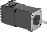
Stepper Motors with Integrated Motion Control
 |
Current per Phase, amp | Overall | Shaft | Temp. Range, ° F | ||||||||||||||||||||||||||||||||||||||||||||||||||||||||||||||||||||||||||||||||||||||||||||||||
|---|---|---|---|---|---|---|---|---|---|---|---|---|---|---|---|---|---|---|---|---|---|---|---|---|---|---|---|---|---|---|---|---|---|---|---|---|---|---|---|---|---|---|---|---|---|---|---|---|---|---|---|---|---|---|---|---|---|---|---|---|---|---|---|---|---|---|---|---|---|---|---|---|---|---|---|---|---|---|---|---|---|---|---|---|---|---|---|---|---|---|---|---|---|---|---|---|---|---|---|
Max. Holding Torque, in·ozf | Max. Rotation Speed, rpm | Min. | Max. | Voltage, V DC | Full Step Increment | Step Resolution | No. of Inputs/Outputs | Lg. | Wd. | Ht. | Dia., mm | Lg., mm | Ctr.-to-Base Lg. | Type | Min. | Max. | Each | ||||||||||||||||||||||||||||||||||||||||||||||||||||||||||||||||||||||||||||||||||
Motor/Controller/Drive/Encoders | |||||||||||||||||||||||||||||||||||||||||||||||||||||||||||||||||||||||||||||||||||||||||||||||||||
NEMA 24 Frame Size | |||||||||||||||||||||||||||||||||||||||||||||||||||||||||||||||||||||||||||||||||||||||||||||||||||
| 340 | 2,400 | 3 | 5 | 12 to 70 | 1.8° | 1 to 1/256 | 1 Analog-Input, 4 Digital-Inputs/Outputs | 4.9" | 2.4" | 3.8" | 8 | 21 | 1.18" | D-Profile | 35 | 100 | 00000000 | 000000000 | |||||||||||||||||||||||||||||||||||||||||||||||||||||||||||||||||||||||||||||||||
