


Filter by
Shaft Diameter
Component
Mounting Position
Body Shape
Voltage
Face Shape

Direction of Operation


Number of Steps per Revolution
Maximum Holding Torque

Export Control Classification Number (ECCN)
Full Step Increment
RoHS
DFARS Specialty Metals
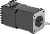
Stepper Motors with Integrated Motion Control
 |
Current per Phase, amp | Overall | Shaft | Temp. Range, ° F | |||||||||||||||||
|---|---|---|---|---|---|---|---|---|---|---|---|---|---|---|---|---|---|---|---|---|
Max. Holding Torque, in·ozf | Max. Rotation Speed, rpm | Min. | Max. | Voltage, V DC | Full Step Increment | Step Resolution | No. of Inputs/Outputs | Lg. | Wd. | Ht. | Dia., mm | Lg., mm | Ctr.-to-Base Lg. | Type | Min. | Max. | Each | |||
Motor/Controller/Drive/Encoders | ||||||||||||||||||||
NEMA 24 Frame Size | ||||||||||||||||||||
| 340 | 2,400 | 3 | 5 | 12 to 70 | 1.8° | 1 to 1/256 | 1 Analog-Input, 4 Digital-Inputs/Outputs | 4.9" | 2.4" | 3.8" | 8 | 21 | 1.18" | D-Profile | 35 | 100 | 6627T107 | 000000000 | ||
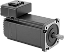
Stepper Servomotors with Integrated Drive
 |
Overall | Shaft | No. of Inputs/Outputs | ||||||||||||||||||
|---|---|---|---|---|---|---|---|---|---|---|---|---|---|---|---|---|---|---|---|---|
Max. Holding Torque, in·ozf | Max. Rotation Speed, rpm | Voltage, V DC | Current, amp | Step Resolution | Full Step Increment | Lg. | Wd. | Ht. | Dia., mm | Lg., mm | Ctr.-to-Base Lg. | Control Communication Protocol | Digital Inputs | Analog Inputs | Digital Outputs | Enclosure Rating | Each | |||
NEMA 23 Frame Size | ||||||||||||||||||||
| 212 | 3,000 | 12 to 70 | 3 | 1 to 1/256 | 1.8° | 5.6" | 2.3" | 3" | 8 | 22.4 | 1.1" | Modbus RTU | 8 | 1 | 4 | IP20 | 5361N22 | 0000000 | ||
| 340 | 3,000 | 12 to 70 | 4 | 1 to 1/256 | 1.8° | 5.6" | 2.3" | 3.2" | 8 | 18 | 1.1" | Modbus TCP/IP | 3 | 1 | 1 | IP20 | 5361N19 | 000000 | ||
| 340 | 3,000 | 12 to 70 | 4.3 | 1 to 1/256 | 1.8° | 5.7" | 2.3" | 3" | 8 | 22.4 | 1.1" | Modbus RTU | 8 | 1 | 4 | IP20 | 5361N23 | 000000 | ||
DC Servomotors
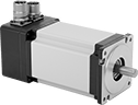 |
Often used for small automation applications, such as pick-and-place machines, these servomotors deliver lots of power in a small package. With accurate positioning and fine motor control, they create rotary motion based on signals from a drive (sold separately). The commands for speed and positioning are the same as those used for stepper motors, so you can upgrade your system without the hassle of reprogramming it. As these servomotors move, their encoder relays the shaft’s distance, direction, and speed back to the drive. The drive increases your system’s efficiency by taking the electrical signal from the encoder and dynamically adapting the motor’s movements, also accounting for inconsistent loads and unexpected forces.
Maximum Torque—Torque generally decreases as speed increases. Use a torque-speed curve to confirm which motor will work for your application. Click on a part number and select "Product Detail" to view the curve for a motor.
Servomotors | Servomotor Encoder Cords | Servomotor Power Cords | |||||||||||||||||
|---|---|---|---|---|---|---|---|---|---|---|---|---|---|---|---|---|---|---|---|
Shaft, mm | |||||||||||||||||||
Motor Frame Size | Max. Torque, in·lbf | Continuous Torque, in·lbf | Max. Rotation Speed, rpm | Current, amp | Max. Current, amp | Wattage, W | Voltage, V DC | Dia. | Lg. | No. of Counts per Rev. | Enclosure Rating | Each | Each | Each | |||||
Without Brake | |||||||||||||||||||
| 40 mm | 8.5 | 2.8 | 2,900 | 5.2 | 15.6 | 100 | 24 | 8 | 22.5 | 10,000 | IP65 | 5082N28 | 0000000 | 5082N102 | 0000000 | 5082N101 | 0000000 | ||
 |
Drives have several control modes that power the motor—step and direction, position, speed, or torque. Use a computer to set motion parameters and calibrate the servomotor to your system. After initial setup, you can use a separate controller, such as a programmable logic controller (PLC), microcontroller, or indexer. A brake resistor protects the drive from regenerated electricity as the motor slows or stops.
Overall, mm | No. of Inputs/Outputs | |||||||||||||
|---|---|---|---|---|---|---|---|---|---|---|---|---|---|---|
For Motor Frame Size | Control Communication Protocol | For Max. Motor Torque | Current, amp | Operating Voltage, V DC | Lg. | Wd. | Ht. | Digital Inputs | Analog Inputs | Outputs | Each | |||
For 24V, 48V, and 60V DC Motor Voltage | ||||||||||||||
| 40 mm, 60 mm, 80 mm | — | 8.5 in·lbf to 61.1 in·lbf | 12 | 24 to 60 | 97 | 41 | 150 | 12 | 2 | 6 | 5082N35 | 0000000 | ||
| 40 mm, 60 mm, 80 mm | Modbus RTU | 8.5 in·lbf to 61.1 in·lbf | 12 | 24 to 60 | 97 | 41 | 150 | 12 | 2 | 6 | 5082N37 | 000000 | ||
| 40 mm, 60 mm, 80 mm | Modbus TCP/IP | 8.5 in·lbf to 61.1 in·lbf | 12 | 24 to 60 | 97 | 41 | 150 | 12 | 2 | 6 | 5082N36 | 000000 | ||
| 40 mm, 60 mm, 80 mm | EtherNet/IP | 8.5 in·lbf to 61.1 in·lbf | 12 | 24 to 60 | 97 | 41 | 150 | 12 | 2 | 6 | 5082N34 | 000000 | ||
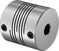
Clamping Precision Flexible Shaft Couplings
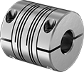 |
Spiral Cut |
Designed to grip evenly around your shaft, these couplings provide more holding power than set screw couplings without marring the shaft. Tighten the clamping screws to secure.
Spiral Cut—Spiral couplings have long cuts in their body for flexibility to handle parallel, axial, and angular misalignment better than parallel couplings. However, they’re not as rigid. Often used for light duty encoder and stepper drive applications, they allow zero backlash (no play) and never need lubrication. They’re also known as helical beam couplings.
7075 Aluminum—7075 aluminum couplings are lightweight with good corrosion resistance.
303 Stainless Steel—303 stainless steel couplings offer excellent corrosion resistance.
Misalignment Capability | ||||||||||||
|---|---|---|---|---|---|---|---|---|---|---|---|---|
For Shaft Diameter | Overall Lg., mm | OD, mm | Max. Rotation Speed, rpm | Max. Torque, in·lbf | Parallel, mm | Angular | Axial, mm | For Rotary Motion | Each | |||
Spiral Cut | ||||||||||||
7075 Aluminum | ||||||||||||
| 8 mm × 1/4" | 30 | 25 | 6,000 | 27 | 0.38 | 3° | 0.25 | Forward/Reverse, Start/Stop | 2464K19 | 000000 | ||
| 8 mm × 3/8" | 30 | 25 | 6,000 | 27 | 0.38 | 3° | 0.25 | Forward/Reverse, Start/Stop | 2464K25 | 00000 | ||
| 8 mm × 3/8" | 38 | 30 | 6,000 | 58 | 0.38 | 3° | 0.25 | Forward/Reverse, Start/Stop | 2464K27 | 000000 | ||
| 8 mm × 1/2" | 38 | 30 | 6,000 | 58 | 0.38 | 3° | 0.25 | Forward/Reverse, Start/Stop | 2464K32 | 000000 | ||
| 8 mm × 5/8" | 38 | 30 | 6,000 | 58 | 0.38 | 3° | 0.25 | Forward/Reverse, Start/Stop | 2464K36 | 000000 | ||
| 8 mm × 6 mm | 30 | 25 | 6,000 | 27 | 0.38 | 3° | 0.25 | Forward/Reverse, Start/Stop | 2463K6 | 00000 | ||
| 8 mm × 7 mm | 30 | 25 | 6,000 | 27 | 0.38 | 3° | 0.25 | Forward/Reverse, Start/Stop | 2463K27 | 00000 | ||
| 8 mm × 8 mm | 30 | 25 | 6,000 | 27 | 0.38 | 3° | 0.25 | Forward/Reverse, Start/Stop | 2463K28 | 00000 | ||
| 8 mm × 8 mm | 38 | 30 | 6,000 | 58 | 0.381 | 3° | 0.25 | Forward/Reverse, Start/Stop | 2463K39 | 000000 | ||
| 9 mm × 8 mm | 30 | 25 | 6,000 | 27 | 0.38 | 3° | 0.25 | Forward/Reverse, Start/Stop | 2463K32 | 00000 | ||
| 9 mm × 8 mm | 38 | 30 | 6,000 | 58 | 0.381 | 3° | 0.25 | Forward/Reverse, Start/Stop | 2463K41 | 000000 | ||
| 10 mm × 8 mm | 30 | 25 | 6,000 | 27 | 0.38 | 3° | 0.25 | Forward/Reverse, Start/Stop | 2463K36 | 00000 | ||
| 10 mm × 8 mm | 38 | 30 | 6,000 | 58 | 0.381 | 3° | 0.25 | Forward/Reverse, Start/Stop | 2463K43 | 000000 | ||
| 11 mm × 8 mm | 38 | 30 | 6,000 | 58 | 0.381 | 3° | 0.25 | Forward/Reverse, Start/Stop | 2463K46 | 000000 | ||
| 12 mm × 8 mm | 38 | 30 | 6,000 | 58 | 0.381 | 3° | 0.25 | Forward/Reverse, Start/Stop | 2463K51 | 000000 | ||
303 Stainless Steel | ||||||||||||
| 6 mm × 8 mm | 30 | 25 | 6,000 | 40 | 0.38 | 3° | 0.25 | Forward/Reverse, Start/Stop | 2463K304 | 000000 | ||
| 8 mm × 8 mm | 30 | 25 | 6,000 | 40 | 0.38 | 3° | 0.25 | Forward/Reverse, Start/Stop | 2463K306 | 000000 | ||
| 8 mm × 9 mm | 30 | 25 | 6,000 | 40 | 0.38 | 3° | 0.25 | Forward/Reverse, Start/Stop | 2463K309 | 000000 | ||
| 8 mm × 10 mm | 30 | 25 | 6,000 | 40 | 0.38 | 3° | 0.25 | Forward/Reverse, Start/Stop | 2463K314 | 000000 | ||
Set Screw Precision Flexible Shaft Couplings
 |
Tighten the set screws to fasten these couplings to your shaft. Set screws bite into the shaft to hold the couplings in place. All are lightweight, corrosion-resistant aluminum.
Spiral Cut—Spiral couplings have long, continuous cuts in the body, making them flexible enough to handle parallel, axial, and angular misalignment. Often used for light duty encoder and stepper drive applications, they allow zero backlash (no play) and never need lubrication. They’re also known as helical beam couplings. Spiral couplings are less rigid than parallel couplings.
Misalignment Capability | |||||||||||
|---|---|---|---|---|---|---|---|---|---|---|---|
For Shaft Diameter | Overall Lg., mm | OD, mm | Max. Rotation Speed | Max. Torque, in·lbf | Angular | Axial, mm | For Rotary Motion | Each | |||
Spiral Cut | |||||||||||
7075 Aluminum | |||||||||||
| 8 mm × 4 mm | 25.4 | 19.1 | Not Rated | 25 | 3° | 0.2 | Forward/Reverse, Start/Stop | 4147N158 | 000000 | ||
| 8 mm × 5 mm | 19.1 | 19.1 | Not Rated | 20 | 3° | 0.15 | Forward/Reverse, Start/Stop | 4147N146 | 00000 | ||
| 8 mm × 5 mm | 25.4 | 19.1 | Not Rated | 25 | 3° | 0.2 | Forward/Reverse, Start/Stop | 4147N159 | 00000 | ||
| 8 mm × 5 mm | 38.1 | 25.4 | Not Rated | 63 | 3° | 0.2 | Forward/Reverse, Start/Stop | 4147N168 | 00000 | ||
| 8 mm × 6 mm | 19.1 | 19.1 | Not Rated | 20 | 3° | 0.15 | Forward/Reverse, Start/Stop | 4147N147 | 00000 | ||
| 8 mm × 6 mm | 25.4 | 19.1 | Not Rated | 25 | 3° | 0.2 | Forward/Reverse, Start/Stop | 4147N161 | 00000 | ||
| 8 mm × 6 mm | 38.1 | 25.4 | Not Rated | 63 | 3° | 0.2 | Forward/Reverse, Start/Stop | 4147N169 | 00000 | ||
| 8 mm × 8 mm | 19.1 | 19.1 | Not Rated | 20 | 3° | 0.15 | Forward/Reverse, Start/Stop | 4147N148 | 00000 | ||
| 8 mm × 8 mm | 25.4 | 19.1 | Not Rated | 25 | 3° | 0.2 | Forward/Reverse, Start/Stop | 4147N162 | 00000 | ||
| 8 mm × 8 mm | 25.4 | 25.4 | Not Rated | 42 | 3° | 0.15 | Forward/Reverse, Start/Stop | 4147N185 | 00000 | ||
| 8 mm × 8 mm | 31.8 | 31.8 | Not Rated | 84 | 3° | 0.15 | Forward/Reverse, Start/Stop | 4147N199 | 000000 | ||
| 8 mm × 8 mm | 38.1 | 25.4 | Not Rated | 63 | 3° | 0.2 | Forward/Reverse, Start/Stop | 4147N171 | 00000 | ||
| 10 mm × 8 mm | 25.4 | 25.4 | Not Rated | 42 | 3° | 0.15 | Forward/Reverse, Start/Stop | 4147N189 | 00000 | ||
| 10 mm × 8 mm | 31.8 | 31.8 | Not Rated | 84 | 3° | 0.15 | Forward/Reverse, Start/Stop | 4147N214 | 000000 | ||
| 10 mm × 8 mm | 38.1 | 25.4 | Not Rated | 63 | 3° | 0.2 | Forward/Reverse, Start/Stop | 4147N175 | 00000 | ||
| 13 mm × 8 mm | 31.8 | 31.8 | Not Rated | 84 | 3° | 0.15 | Forward/Reverse, Start/Stop | 4147N224 | 000000 | ||
