Jack Posts
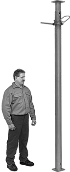
Support beams and joists.
To adjust the height of locking-pin jack posts, extend the post to the approximate height needed and insert the locking pin through the hole to secure. Then turn the threaded handle counterclockwise to raise it up to 6" for more precise height adjustments.
To adjust the height of locking-ring jack posts, slide the safety lock into the notch to secure at the approximate height needed. Then turn the 10" long handle for final height adjustments.
Ht. | Capacity | Base | Top Plate | |||||||||||
|---|---|---|---|---|---|---|---|---|---|---|---|---|---|---|
| Min. | Max. | @ Min. Ht. | @ Max. Ht. | Material | Wd. | Dp. | Wd. | Dp. | Mounting Hole Dia. (No. of) | Mounting Fasteners Included | Center-to-Center Adjustments | Handle Lg. | Each | |
Locking Pin | ||||||||||||||
| 78" | 138" | 6,400 lbs. @ 78" | 3,800 lbs. @ 138" | Steel | 4 3/4" | 4 3/4" | 4 3/4" | 4 3/4" | 9/16" (8) | No | 6" | __ | 0000000 | 0000000 |
| 120" | 216" | 9,300 lbs. @ 120" | 2,700 lbs. @ 216" | Steel | 4 3/4" | 4 3/4" | 4 3/4" | 4 3/4" | 9/16" (8) | No | 6" | __ | 0000000 | 000000 |
Locking Ring | ||||||||||||||
| 16" | 24" | 18,000 lbs. @ 16" | 18,000 lbs. @ 24" | Steel | 4" | 4" | 4" | 4" | 3/8" (4), 5/8" (4) | No | 4" | 10" | 000000 | 000000 |
| 25" | 41" | 18,000 lbs. @ 25" | 17,000 lbs. @ 41" | Steel | 4" | 4" | 4" | 4" | 3/8" (4), 5/8" (4) | No | 4" | 10" | 000000 | 000000 |
| 40" | 64" | 18,000 lbs. @ 40" | 17,000 lbs. @ 64" | Steel | 4" | 4" | 4" | 4" | 3/8" (4), 5/8" (4) | No | 4" | 10" | 000000 | 000000 |
| 68" | 100" | 17,000 lbs. @ 68" | 14,000 lbs. @ 100" | Steel | 4" | 4" | 4" | 4" | 3/8" (4), 5/8" (4) | No | 4" | 10" | 000000 | 000000 |
Jack Stands—Not for Lifting

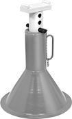
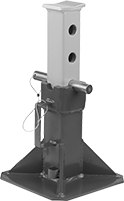
After raising a load, add these steel stands for support.
Locking handles lock the ratchet bar in place to support the load.
Locking pins are inserted through the riser to lock the bar in place.
Note: Do not raise or lower stands while under load. Always use stands in pairs and on a hard, flat surface.
Warning: Never use to support people or loads over people.
Capacity per Pair | Saddle | Base | |||||||||
|---|---|---|---|---|---|---|---|---|---|---|---|
| tons | lbs. | Ht. | Ht. Adjustment Increments | Lg. | Wd. | Dia. | Lg. | Wd. | Pair | ||
Locking Handle | |||||||||||
| A | 6 | 12,000 | 12"-17 3/4" | 9/16" | 1" | 3 1/2" | __ | 7 1/2" | 8 1/4" | 0000000 | 000000 |
| A | 12 | 24,000 | 15 5/8"-23 3/4" | 11/16" | 1 1/4" | 4 1/4" | __ | 10 3/8" | 11 5/8" | 0000000 | 000000 |
Locking Pin | |||||||||||
| B | 12 | 24,000 | 19"-29 1/2" | 1 1/2" | 3" | 6" | 15 7/8" | __ | __ | 0000000 | 000000 |
| C | 44 | 88,000 | 13 7/8"-19 7/8" | 3" | 3" | 3 3/4" | __ | 11" | 11" | 0000000 | 000000 |
Screw Jack Stands
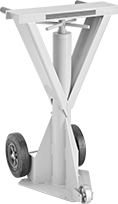
Hold and adjust the height of heavy loads such as truck trailers. The screw adjustment lets you make small changes to the height of your load.
Note: Jack stands should not be moved when under load.
Warning: Never use to support people or loads over people.

Cap. | Holding Cap. | Saddle | ||||||||
|---|---|---|---|---|---|---|---|---|---|---|
| tons | lbs. | tons | lbs. | Ht. | Max. Lift | Lg. | Wd. | Base Dia. | Each | |
| 2 1/2 | 5,000 | 25 | 50,000 | 44"-51" | 7" | 5" | 5" | 14" | 0000000 | 0000000 |

Cap. | Holding Cap. | Saddle | Base | ||||||||||||
|---|---|---|---|---|---|---|---|---|---|---|---|---|---|---|---|
| tons | lbs. | tons | lbs. | Ht. | Max. Lift | Dia. | Lg. | Wd. | Lg. | Wd. | Handle Lg. | Wheel Material | Features | Each | |
With Two Axle-Mounted Wheels | |||||||||||||||
| 20 | 40,000 | 50 | 100,000 | 39"-51" | 11 1/2" | 8" | __ | __ | 16" | 17 5/8" | 20" | Rubber | Removable Handle | 0000000 | 0000000 |
With Three Axle-Mounted Wheels | |||||||||||||||
| 20 | 40,000 | 50 | 100,000 | 40"-51" | 11 1/2" | __ | 24" | 6" | 16" | 17 5/8" | 20" | Rubber, Steel | Removable Handle | 0000000 | 000000 |


| Component | For Wheel Configuration | Wheel Material | Includes | Each | |
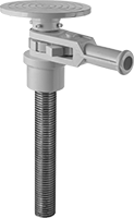
| Grip for Stationary Jack Stands | __ | __ | __ | 0000000 | 000000 |
| Grip for Mobile Jack Stands | Two Axle-Mounted Wheels, Three Axle-Mounted Wheels | __ | __ | 0000000 | 0000 |
| Handle for Mobile Jack Stands | Two Axle-Mounted Wheels, Three Axle-Mounted Wheels | __ | 1 Grip | 0000000 | 00000 |
| Saddle for Mobile Jack Stands | Two Axle-Mounted Wheels | __ | __ | 0000000 | 000000 |
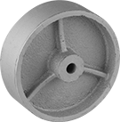
| Wheel for Mobile Jack Stands | Three Axle-Mounted Wheels | Steel | __ | 0000000 | 00000 |
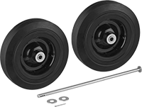
| Wheel Kit for Mobile Jack Stands | Two Axle-Mounted Wheels, Three Axle-Mounted Wheels | Rubber | 1 Axle, 1 Cotter Pin, 2 Wheels | 0000000 | 000000 |
Ratchet Jack Stands
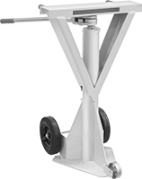
The ratcheting action of these jacks stands makes adjusting them under load easier than screw jack stands. Use them to hold and adjust the height of heavy loads such as truck trailers.
Note: Jack stands should not be moved when under load.
Warning: Never use to support people or loads over people.

Cap. | Holding Cap. | Saddle | Base | ||||||||||||
|---|---|---|---|---|---|---|---|---|---|---|---|---|---|---|---|
| tons | lbs. | tons | lbs. | Ht. | Max. Lift | Dia. | Lg. | Wd. | Lg. | Wd. | Handle Lg. | Wheel Material | Features | Each | |
With Two Axle-Mounted Wheels | |||||||||||||||
| 20 | 40,000 | 50 | 100,000 | 39"-51" | 12" | 8" | __ | __ | 16" | 17 5/8" | 20" | Rubber | Removable Handle | 0000000 | 0000000 |
With Three Axle-Mounted Wheels | |||||||||||||||
| 20 | 40,000 | 50 | 100,000 | 40"-51" | 11 1/2" | __ | 24" | 6" | 16" | 17 5/8" | 20" | Rubber and Steel | Removable Handle | 0000000 | 000000 |


| Component | For Wheel Configuration | Wheel Material | Includes | Each | |
| Grip | Two Axle-Mounted Wheels, Three Axle-Mounted Wheels | __ | __ | 0000000 | 00000 |
| Handle | Two Axle-Mounted Wheels, Three Axle-Mounted Wheels | __ | 1 Grip | 0000000 | 00000 |
| Saddle | Two Axle-Mounted Wheels | __ | __ | 0000000 | 000000 |
| Wheel | Three Axle-Mounted Wheels | Steel | __ | 0000000 | 00000 |
| Wheel Kit | Two Axle-Mounted Wheels, Three Axle-Mounted Wheels | Rubber | 1 Axle, 1 Cotter Pin, 2 Wheels | 0000000 | 000000 |
Trench Braces
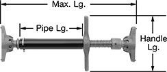
Support trench walls when installing pipes, cables, and other buried equipment. The ends tilt up to 10° for angular shoring and have spikes that dig into surfaces for a tight grip.
Screw the handle to adjust the length of the brace. The included pipe can be replaced with a piece of Schedule 40 pipe. Braces with a pipe size of 1 1/2 can accommodate pipe up to 40" long. Braces with a pipe size of 2 can accommodate pipe up to 50" long.
| Cap., lbs. | Lg. | Pipe Lg. | Pipe Size | Thread Type | Handle Lg. | Base Wd. | Base Dp. | Screw Size | Max. Wall Angle | Material | Base Material | Each | |
| 16,000 | 18 1/2"-25 1/2" | 10 1/2" | 1 1/2 | NPT | 9 1/2" | 3" | 6" | 1 3/8" | 10° | Steel | Iron | 0000000 | 0000000 |
| 16,000 | 30 1/2"-41" | 22 1/2" | 1 1/2 | NPT | 9 1/2" | 3" | 6" | 1 3/8" | 10° | Steel | Iron | 0000000 | 000000 |
| 26,000 | 38"-52" | 26" | 2 | NPT | 11" | 4 1/4" | 8" | 1 7/8" | 10° | Steel | Iron | 0000000 | 000000 |
| 26,000 | 50"-64" | 38" | 2 | NPT | 11" | 4 1/4" | 8" | 1 7/8" | 10° | Steel | Iron | 0000000 | 000000 |
Leveling Micrometer Heads


Precisely level heavy machines, surface plates, and other devices when accuracy is crucial. Turn the handle to adjust their height, even when under a machine.
Overall | |||||||||||||
|---|---|---|---|---|---|---|---|---|---|---|---|---|---|
| Measuring Range, mm | Measuring Increments, mm | Point Angle | Spindle Face Material | Capacity, lbs. | Wd. | Ht. | Base Dia. | Handle Lg. | Features | Manufacturer | Manufacturer Model Number | Each | |
Plain Thimble—Rotating Spindle | |||||||||||||
| 60 to 75 | 0.01 | 90° | Steel | 850 | 4 19/32" | 2 3/8" | 2 17/32" | 3 11/32" | Handle | Mitutoyo | 7850 | 0000000 | 0000000 |


