


Choosing a Proximity Switch
More
Choosing an Electrical Switch
More
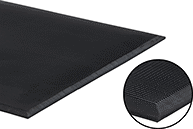
Safety Switch Mats
Prevent personnel from getting too close to dangerous equipment while it’s running. Step anywhere on these mats and they can turn on warning lights and alarms or shut down equipment. To minimize circuit damage, they also activate if they detect any malfunctions in your equipment’s electrical system. A complete switch requires a mat and a controller (sold separately). Together they meet ANSI/RIA R15.06 safety requirements. Mats are rated IP65 for protection from washdowns.
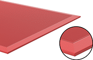
Red mats are easy to spot in crowded areas and in dim light. They help you avoid stepping on them if you don’t want to stop machinery or to find them quickly if you do.
Optional frames secure mats to the floor. Punch holes in the frame to insert a screw anywhere along the length.
Mats | |||||||||||||||||
|---|---|---|---|---|---|---|---|---|---|---|---|---|---|---|---|---|---|
Wire Leads | Optional Frames | ||||||||||||||||
| Wd. | Lg. | Thick. | No. of Circuits Controlled | Switch Starting Position | Switch Action | Industry Designation | Switching Current @ Voltage | Actuation Force, lbs. | Max. Pressure, psi | No. of | Lg., ft. | Ga. | Material | Each | Each | ||
Black | |||||||||||||||||
| 24" | 36" | 1/2" | 1 | 1 Off (Normally Open) | Springs Back (Momentary) | SPST-NO | 1 A @ 24 V AC/24 V DC | 22 | 1,100 | 4 | 6 | 18 | PVC Plastic | 0000000 | 0000000 | 0000000 | 0000000 |
| 24" | 48" | 1/2" | 1 | 1 Off (Normally Open) | Springs Back (Momentary) | SPST-NO | 1 A @ 24 V AC/24 V DC | 22 | 1,100 | 4 | 6 | 18 | PVC Plastic | 0000000 | 000000 | 0000000 | 000000 |
| 24" | 60" | 1/2" | 1 | 1 Off (Normally Open) | Springs Back (Momentary) | SPST-NO | 1 A @ 24 V AC/24 V DC | 22 | 1,100 | 4 | 6 | 18 | PVC Plastic | 0000000 | 000000 | 0000000 | 000000 |
| 24" | 72" | 1/2" | 1 | 1 Off (Normally Open) | Springs Back (Momentary) | SPST-NO | 1 A @ 24 V AC/24 V DC | 22 | 1,100 | 4 | 6 | 18 | PVC Plastic | 0000000 | 00000000 | 0000000 | 000000 |
| 36" | 48" | 1/2" | 1 | 1 Off (Normally Open) | Springs Back (Momentary) | SPST-NO | 1 A @ 24 V AC/24 V DC | 22 | 1,100 | 4 | 6 | 18 | PVC Plastic | 0000000 | 00000000 | 0000000 | 000000 |
| 36" | 60" | 1/2" | 1 | 1 Off (Normally Open) | Springs Back (Momentary) | SPST-NO | 1 A @ 24 V AC/24 V DC | 22 | 1,100 | 4 | 6 | 18 | PVC Plastic | 0000000 | 00000000 | 0000000 | 000000 |
| 36" | 72" | 1/2" | 1 | 1 Off (Normally Open) | Springs Back (Momentary) | SPST-NO | 1 A @ 24 V AC/24 V DC | 22 | 1,100 | 4 | 6 | 18 | PVC Plastic | 0000000 | 00000000 | 0000000 | 000000 |
| 48" | 72" | 1/2" | 1 | 1 Off (Normally Open) | Springs Back (Momentary) | SPST-NO | 1 A @ 24 V AC/24 V DC | 22 | 1,100 | 4 | 6 | 18 | PVC Plastic | 0000000 | 00000000 | 0000000 | 000000 |
Red | |||||||||||||||||
| 24" | 36" | 1/2" | 1 | 1 Off (Normally Open) | Springs Back (Momentary) | SPST-NO | 1 A @ 24 V AC/24 V DC | 22 | 1,100 | 4 | 6 | 18 | PVC Plastic | 00000000 | 000000 | 0000000 | 000000 |
| 24" | 48" | 1/2" | 1 | 1 Off (Normally Open) | Springs Back (Momentary) | SPST-NO | 1 A @ 24 V AC/24 V DC | 22 | 1,100 | 4 | 6 | 18 | PVC Plastic | 00000000 | 000000 | 0000000 | 000000 |
| 36" | 48" | 1/2" | 1 | 1 Off (Normally Open) | Springs Back (Momentary) | SPST-NO | 1 A @ 24 V AC/24 V DC | 22 | 1,100 | 4 | 6 | 18 | PVC Plastic | 00000000 | 00000000 | 0000000 | 000000 |
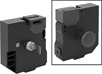
Frame-Mounted Safety Switches
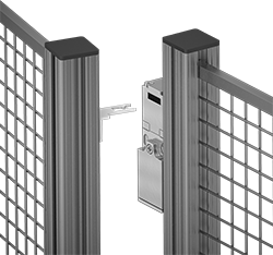
Also known as interlock switches, these ensure the safety of personnel by automatically shutting off power to machinery when an access door opens. Mount the switch to the door frame and mount a key to the door so that the key is inserted into the switch when the door is closed. When the door opens, the key is removed from the switch and the machine shuts down. They’re often used with machine guards for large robots.
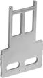
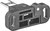
All switches require an actuator key, but not all include one—check whether you need to pick out a separate actuator key. For some switch styles, you can also select the mounting orientation of the key. Flexible keys pivot at least 15°, making them easier to align with switches during installation.
Style A-G switches have positive-force, normally closed contacts that will open a circuit when the switch is actuated even if a spring fails or the contacts stick.
Style J switches have extra safety controls to prevent you from getting trapped next to running machinery. They actuate with the turn of a portable key. Bring the key when you enter an enclosure to ensure machinery won’t start while you’re inside, even if the door closes behind you. As an added fail-safe, a rear release button lets you cut power from inside of enclosures if needed. These switches have light-up indicators that show when they're properly installed and whether they're actuated.
IP67 rated switches protect against temporary submersion.
Housing | Conduit | ||||||||||||||||
|---|---|---|---|---|---|---|---|---|---|---|---|---|---|---|---|---|---|
| Style | No. of Circuits Controlled | Switch Starting Position | Switch Action | No. of Terminals | Industry Designation | Switching Current @ Voltage | Max. Voltage | Ht. | Wd. | Dp. | Trade Size | Thread Size | Thread Type | Key Included | Environmental Rating | Each | |
Screw Terminal Connection with Positive-Force Normally Closed Contacts | |||||||||||||||||
| D | 3 | 1 Off (Normally Open) and 2 On (Normally Closed) | Stays Switched (Maintained) | 6 | 3PST-1NO/2NC | 6 A @ 120 V AC, 0.27 A @ 24 V DC | 240V AC 250V DC | 3.8" | 1.2" | 1.2" | 1/2 | __ | NPT | Yes | IP67 | 00000000 | 000000 |
Screw Terminal Connection with Rear Release Button, Portable Key, and LED Status Indicator | |||||||||||||||||
| J | 6 | 2 Off (Normally Open) and 4 On (Normally Closed) | Stays Switched (Maintained) | 12 | 6PST-2NO/4NC | 3 A @ 240 V AC, 2.5 A @ 250 V DC | 240V AC 250V DC | 5.2" | 4.6" | 2.2" | __ | M20 | Metric | Yes | IP67 | 000000000 | 000000 |

O'all | |||||||
|---|---|---|---|---|---|---|---|
| Angle Range | Adjustability | Lg. | Wd. | Mounting Fasteners Included | Each | ||
Straight Keys | |||||||
| For Style J | __ | __ | 61.5 mm | 40 mm | No | 000000000 | 000000 |
90° Angle Keys | |||||||
| For Style J | __ | __ | 45 mm | 40 mm | No | 000000000 | 00000 |
Flexible Keys | |||||||
| For Style D | 0°-15° | Up/Down/Left/Right | 48.9 mm | 55 mm | No | 000000000 | 00000 |
| For Style J | 0°-18° | Left/Right | 70 mm | 40 mm | No | 000000000 | 00000 |
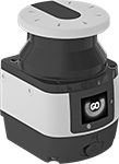
Safety Laser Scanners
Monitor a wide area around dangerous machinery. If a person or object gets too close, these scanners signal your relay or controller to either trigger a warning or shut down the machinery. For example, they can slow a robotic arm if someone comes within 20 ft., then stop it completely if they come within 10 ft. You can also set these scanners to respond only when they detect objects of a certain size. Since they continuously monitor 275°, they cover a much wider area than light beam safety barrier switches.
These scanners have a dedicated safety output for triggering emergency stops, and three inputs/outputs that you can configure. The safety output sends two duplicate signals at the same time—also called redundant signals—so even if one fails, the other will stop your equipment. Wire this output to safety relays or safety terminals on a controller. The inputs/outputs can be configured to set off warnings or adjust the scanner’s behavior. When used as outputs, they can send a signal to flash a light, sound an alarm, or slow a machine. When used as inputs, they can signal the scanner to ignore robot arms or other expected objects, while still scanning for people and unexpected objects.
Download free software onto a computer running Windows to set the monitoring distance, the size of the objects you want to detect, and the function of the inputs/outputs. You can also save up to six different configurations on the scanner itself.
Rated IP65, these switches are sealed to keep out dust and low-pressure jets of water. They’re UL and C-UL listed, CE marked, and TUV SUD certified, so they meet U.S. and international safety standards. They also meet EN, ISO, and IEC standards for performance and safety.
You’ll need a power/input/output cable to connect the scanner to your power supply, controller, or relay. Use an ethernet cord to connect the scanner to your computer for programming.
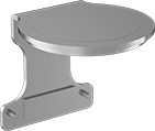
Mount these scanners to a flat surface using holes on the back. Add a mounting bracket to tilt the scanner toward the area you want to monitor. To shield the top of your scanner from falling objects and collisions, mount a protective bracket onto the mounting bracket.

| Safety Sensing Distance Range | No. of Safety Outputs | Configurable Input/Output Sensing Distance Range | No. of Configurable Inputs/Outputs | Min. Object Size Detected | Signal Input/Output Type | Input Voltage | Max. Sensing Angle | Wd. | Ht. | Dp. | Housing Material | Housing Color | Each | |
8-Pole M12 Socket Connection | ||||||||||||||
|---|---|---|---|---|---|---|---|---|---|---|---|---|---|---|
| 2"-9.8 ft. | 1 | 2"-131.2 ft. | 3 | 1.2" | PNP | 24V DC | 275° | 4" | 6" | 4.4" | Powder-Coated Aluminum | Yellow | 0000000 | 000000000 |
| 2"-18 ft. | 1 | 2"-131.2 ft. | 3 | 1.2" | PNP | 24V DC | 275° | 4" | 6" | 4.4" | Powder-Coated Aluminum | Yellow | 0000000 | 00000000 |
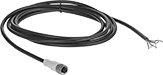
| Number of Poles | Transmission Speed, Mbps | Wire Gauge | Cord OD | Shielding | Shield Type | Temp. Range, °F | Cord Insulation Material | Color | Each | |
9 1/2 ft. Lg. | ||||||||||
|---|---|---|---|---|---|---|---|---|---|---|
D-Coded—Ethernet Cable Category 5E | ||||||||||
| 4 | 100 | 24 | 0.26" | Double Shielded | Braid, Foil | -40° to 175° | TPE Rubber | Blue | 00000000 | 000000 |
32 1/2 ft. Lg. | ||||||||||
D-Coded—Ethernet Cable Category 5E | ||||||||||
| 4 | 100 | 24 | 0.26" | Double Shielded | Braid, Foil | -40° to 175° | TPE Rubber | Blue | 00000000 | 000000 |
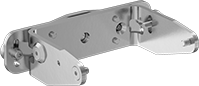
| Material | Mounting Fasteners Included | Each | |
| Zinc-Plated Steel | Yes | 0000000 | 000000 |
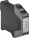
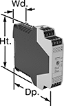
Safety Relays with Diagnostic Capabilities
Control and diagnose issues with safety-critical circuits. These relays have a microprocessor that monitors safety components, such as emergency stops and light curtains, and sends a signal to stop the operation if a failure is detected and restart when the issue is resolved. They also help with diagnostic tasks because of their feedback circuit, which allows basic relays to communicate their status back to the safety relay. These relays have a duplicate set of input and output signals, so they’ll still stop the controlled device if one of the inputs fails.
IP20 rated, they have recessed terminals which prevent fingers and other objects from touching live circuits. These relays have been tested to multiple safety standards and can help achieve PL, SIL, or CAT system ratings. They also meet ISO and IEC standards for machine safety.
Mount them to 35 mm DIN rail (also known as DIN 3 Rail) for fast installation.
Auxiliary contact blocks (sold separately) allow you to control more components, such as signaling devices or basic relays.
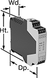
| Number of Terminals | Input Voltage | Switching Current @ Voltage | Max. Switching Voltage | Ht. | Wd. | Dp. | For Use With | Max. System Safety Rating | Features | Each | |
3 Circuits Controlled | |||||||||||
|---|---|---|---|---|---|---|---|---|---|---|---|
3 Safety Outputs with 3 Off (Normally Open) | |||||||||||
| 6 | 24V DC | 6 A @ 240 V AC 6 A @ 24 V DC | 240V AC | 3.7" | 0.9" | 4.8" | Light Curtains | PLe, SIL3 | Auxiliary PNP Output, Self-Monitoring Circuitry | 0000000 | 0000000 |

| Number of Terminals | Input Voltage | Switching Current @ Voltage | Max. Switching Voltage | Ht. | Wd. | Dp. | Features | Each | |
5 Safety Outputs | |||||||||
|---|---|---|---|---|---|---|---|---|---|
| 16 | 24V AC, 24V DC | 2.5 A @ 24 V DC 3 A @ 240 V AC | 250V AC, 250V DC | 3.9" | 0.9" | 4.5" | __ | 0000000 | 0000000 |
4 Delayed Safety Outputs | |||||||||
| 16 | 24V DC | 3 A @ 240 V AC 3 A @ 24 V DC | 250V AC, 250V DC | 3.9" | 0.9" | 4.5" | Time Delay | 0000000 | 000000 |