


Filter by
Actuator Style


System of Measurement
Hazardous Location Rating
Housing Material
Switch Action

Enclosure Rating
Push-Button Style


For Use With
Pressure Set Point


Horsepower @ Switching Voltage
Switch Starting Position


Export Control Classification Number (ECCN)
DFARS Specialty Metals
Hazardous Location Enclosed Motor Switches
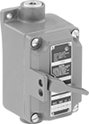 |
Safely turn motors on and off near ignitable gases and dust—the housing on these switches seals in anything that could ignite flammable material. Made from aluminum, the housing is lightweight and durable. It guards against water, oil, and other materials that could cause damage. Even in harsh conditions, there’s no need to mount these switches inside an electrical panel.
You need to grip and twist the lever to actuate these switches, so they won’t accidentally turn on or off if something bumps into them. In addition to starting and stopping motors, they work with other circuits, such as lighting and electric heat circuits. They don’t provide overload protection.
Switching | |||||||||||||||||
|---|---|---|---|---|---|---|---|---|---|---|---|---|---|---|---|---|---|
No. of Circuits Controlled | Electrical Phase (hp) | Switch Starting Position | Switch Designation | Current, amp | Voltage, V AC | Housing Material | Ht. | Wd. | Wire Connection | Environment | Hazardous Location Rating | Enclosure Rating | Certification | Each | |||
Maintained | |||||||||||||||||
Lever Actuator | |||||||||||||||||
| 2 | Single (3 hp @ 240V AC) | 2 Off | DPST-NO | 30 | 600 | Painted Aluminum | 6.5" | 3" | Screw Terminal | Hazardous | NEC Class I Divisions 1, 2 Groups C, D NEC Class II Divisions 1, 2 Groups E, F, G | NEMA 7, NEMA 9 | UL Listed, C-UL Listed, CSA Certified | 7657K32 | 0000000 | ||
| 3 | Three (7 1/2 hp @ 240V AC) | 3 Off | 3PST-NO | 30 | 600 | Painted Aluminum | 6.5" | 3" | Screw Terminal | Hazardous | NEC Class I Divisions 1, 2 Groups C, D NEC Class II Divisions 1, 2 Groups E, F, G | NEMA 7, NEMA 9 | UL Listed, C-UL Listed, CSA Certified | 7657K22 | 000000 | ||
Hazardous Location Pressure Switches
 |  |
Style A | Style B |
Built with an explosion-proof enclosure to meet NEMA 7 and 9 standards for hazardous locations, these switches were tested and verified by UL and CSA for use where explosive liquids, dust, and gas are present. When they reach the set pressure, they power equipment, signal controls, or trigger alarms. They’re single pole, double throw (SPDT) and can be installed to turn one circuit from off to on (normally open) or from on to off (normally closed). In addition to being UL listed and CSA certified, these switches are CE marked, so they also meet European safety standards.
All switches are IP and NEMA rated for use outdoors and protection from some corrosion, dust, and spraying water.
Wire Lead Connection
| |
Style A | Style B |
IP67 Enclosure Rating and NEMA 4X Enclosure Rating—IP67 and NEMA 4X rated switches seal out water from temporary submersion and have increased protection against corrosion, similar to 304 stainless steel.
Style | Pressure Set Point Range, psi | Approx. Difference Between Set Point and Reset Point, psi | Max. Continuous Pressure, psi | Max. Short-Term Pressure, psi | Accuracy | Max. Switching Current @ Voltage | Process Temp. Range, ° F | Connection Material | For Use With | Enclosure Rating | Hazardous Location Rating | Certification | Each | |||
|---|---|---|---|---|---|---|---|---|---|---|---|---|---|---|---|---|
1/4 Threaded NPT Male Pipe | ||||||||||||||||
Internal Adjustment | ||||||||||||||||
| A | 8 to 60 | 5 | 60 | 1,000 | ±5% | 5 amp @ 125V AC 5 amp @ 250V AC | -40 to 190 | 316 Stainless Steel | Air, Diesel Fuel, Gasoline, Hydraulic Fluid, Natural Gas, Water | IP67, NEMA 4X, NEMA 7, NEMA 9 | NEC Class I Divisions 1, 2 Groups A, B, C, D NEC Class II Divisions 1, 2 Groups E, F, G | CE Marked, CSA Certified, UL Listed | 46985K71 | 0000000 | ||
| A | 10 to 100 | 9 | 100 | 1,000 | ±5% | 5 amp @ 125V AC 5 amp @ 250V AC | -40 to 190 | 316 Stainless Steel | Air, Diesel Fuel, Gasoline, Hydraulic Fluid, Natural Gas, Water | IP67, NEMA 4X, NEMA 7, NEMA 9 | NEC Class I Divisions 1, 2 Groups A, B, C, D NEC Class II Divisions 1, 2 Groups E, F, G | CE Marked, CSA Certified, UL Listed | 46985K72 | 000000 | ||
| A | 20 to 200 | 16 | 200 | 1,000 | ±2% | 5 amp @ 125V AC 5 amp @ 250V AC | -40 to 190 | 316 Stainless Steel | Air, Diesel Fuel, Gasoline, Hydraulic Fluid, Natural Gas, Water | IP67, NEMA 4X, NEMA 7, NEMA 9 | NEC Class I Divisions 1, 2 Groups A, B, C, D NEC Class II Divisions 1, 2 Groups E, F, G | CE Marked, CSA Certified, UL Listed | 46985K73 | 000000 | ||
| A | 50 to 500 | 60 | 500 | 5,000 | ±2% | 5 amp @ 125V AC 5 amp @ 250V AC | -40 to 190 | 316 Stainless Steel | Air, Diesel Fuel, Gasoline, Hydraulic Fluid, Natural Gas, Water | IP67, NEMA 4X, NEMA 7, NEMA 9 | NEC Class I Divisions 1, 2 Groups A, B, C, D NEC Class II Divisions 1, 2 Groups E, F, G | CE Marked, CSA Certified, UL Listed | 46985K74 | 000000 | ||
| A | 100 to 1,000 | 87 | 1,000 | 5,000 | ±2% | 5 amp @ 125V AC 5 amp @ 250V AC | -40 to 190 | 316 Stainless Steel | Air, Diesel Fuel, Gasoline, Hydraulic Fluid, Natural Gas, Water | IP67, NEMA 4X, NEMA 7, NEMA 9 | NEC Class I Divisions 1, 2 Groups A, B, C, D NEC Class II Divisions 1, 2 Groups E, F, G | CE Marked, CSA Certified, UL Listed | 46985K75 | 000000 | ||
| A | 200 to 2,000 | 165 | 2,000 | 5,000 | ±2% | 5 amp @ 125V AC 5 amp @ 250V AC | -40 to 190 | 316 Stainless Steel | Air, Diesel Fuel, Gasoline, Hydraulic Fluid, Natural Gas, Water | IP67, NEMA 4X, NEMA 7, NEMA 9 | NEC Class I Divisions 1, 2 Groups A, B, C, D NEC Class II Divisions 1, 2 Groups E, F, G | CE Marked, CSA Certified, UL Listed | 46985K76 | 000000 | ||
1/2 Threaded NPT Female Pipe | ||||||||||||||||
Internal Adjustment | ||||||||||||||||
| B | 6 to 30 | 2 | 30 | 1,000 | ±1% | 5 amp @ 125V AC 5 amp @ 250V AC | 0 to 200 | 316 Stainless Steel | Air, Diesel Fuel, Gasoline, Hydraulic Fluid, Natural Gas, Water | IP66, NEMA 4, NEMA 7, NEMA 9 | NEC Class I Divisions 1, 2 Groups A, B, C, D NEC Class II Divisions 1, 2 Groups E, F, G | CE Marked, CSA Certified, UL Listed | 46985K61 | 000000 | ||
| B | 12 to 60 | 2 | 60 | 1,000 | ±1% | 5 amp @ 125V AC 5 amp @ 250V AC | 0 to 200 | 316 Stainless Steel | Air, Diesel Fuel, Gasoline, Hydraulic Fluid, Natural Gas, Water | IP66, NEMA 4, NEMA 7, NEMA 9 | NEC Class I Divisions 1, 2 Groups A, B, C, D NEC Class II Divisions 1, 2 Groups E, F, G | CE Marked, CSA Certified, UL Listed | 46985K62 | 000000 | ||
| B | 20 to 100 | 3.5 | 100 | 1,000 | ±1% | 5 amp @ 125V AC 5 amp @ 250V AC | 0 to 200 | 316 Stainless Steel | Air, Diesel Fuel, Gasoline, Hydraulic Fluid, Natural Gas, Water | IP66, NEMA 4, NEMA 7, NEMA 9 | NEC Class I Divisions 1, 2 Groups A, B, C, D NEC Class II Divisions 1, 2 Groups E, F, G | CE Marked, CSA Certified, UL Listed | 46985K63 | 000000 | ||
| B | 40 to 200 | 6.5 | 200 | 1,000 | ±1% | 5 amp @ 125V AC 5 amp @ 250V AC | 0 to 200 | 316 Stainless Steel | Air, Diesel Fuel, Gasoline, Hydraulic Fluid, Natural Gas, Water | IP66, NEMA 4, NEMA 7, NEMA 9 | NEC Class I Divisions 1, 2 Groups A, B, C, D NEC Class II Divisions 1, 2 Groups E, F, G | CE Marked, CSA Certified, UL Listed | 46985K64 | 000000 | ||
| B | 80 to 400 | 11 | 400 | 1,600 | ±1% | 5 amp @ 125V AC 5 amp @ 250V AC | 0 to 200 | 316 Stainless Steel | Air, Diesel Fuel, Gasoline, Hydraulic Fluid, Natural Gas, Water | IP66, NEMA 4, NEMA 7, NEMA 9 | NEC Class I Divisions 1, 2 Groups A, B, C, D NEC Class II Divisions 1, 2 Groups E, F, G | CE Marked, CSA Certified, UL Listed | 46985K65 | 000000 | ||
Hazardous Location Enclosed Push-Button Switches
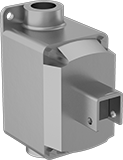 | 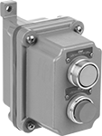 |  |
1 Flush Push Button | 1 Flush Push Button and 1 Projecting Push Button | Start |
Mounting | ||||||||||||||||
|---|---|---|---|---|---|---|---|---|---|---|---|---|---|---|---|---|
Message (Actuator Color) | No. of Circuits Controlled per Button | Switch Starting Position | Switch Action | No. of Terminals per Button | Switch Designation | Switching Current @ Voltage | Max. Voltage, V AC | Conduit Trade Size | Fasteners Included | No. of Holes | Hole Dia. | Enclosure Rating | Each | |||
Aluminum Housing with Screw-Terminal Wire Connection | ||||||||||||||||
1 Flush Push Button | ||||||||||||||||
| Start (Black) | 1 | 1 Off and 1 On | Momentary | 4 | DPST-1NO/1NC | 10 amp @ 120V AC | 600 | 3/4 | No | 2 | 5/16" | NEMA 3, NEMA 7, NEMA 9 | 6883K61 | 0000000 | ||
1 Flush Push Button and 1 Projecting Push Button | ||||||||||||||||
| Start (Green), Stop (Red), | 2 | 1 Off and 1 On | Momentary | 2 | DPST-1NO/1NC | 10 amp @ 120V AC | 600 | 3/4 | No | 2 | 9/32" | NEMA 3, NEMA 7, NEMA 9 | 6883K55 | 000000 | ||
Hazardous Location Limit Switches
 |  |
Plunger Actuator | Wobble Stick Actuator |
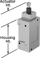
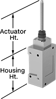
Safely open or close a circuit near ignitable gases and dust—the housing on these switches seals in anything that could ignite flammable material. You'll know they're safe because they're NEC Class I, Divisions 1, 2 Groups B, C, and D; and Class II, Divisions 1, 2 Groups E, F, and G certified for hazardous locations. These switches send a signal to your circuit when an object hits the actuator—for instance, a box on a conveyor runs into the switch, stopping the conveyor. They open and close circuits as fast as snap-acting switches, but they have a bigger actuator for large objects.
Plunger Actuator—Switches with a plunger actuator let you adjust the actuator’s height to easily align it with your target. They require a push to activate, similar to a button.
Wobble Stick Actuator—Switches with a wobble stick actuator have an arm that rotates 360°, so you don’t need to align it in a specific direction. The actuator won’t snap if pushed backward, such as if there’s a jam in your system.
Housing | |||||||||||||||||||
|---|---|---|---|---|---|---|---|---|---|---|---|---|---|---|---|---|---|---|---|
No. of Circuits Controlled | Switch Starting Position | Switch Action | Switch Designation | Switching Current @ Voltage | Max. Voltage | Actuation Torque, in·ozf | Operating Temp. Range, ° F | Actuator Ht. | No. of Terminals | Lg. | Ht. | Dp. | Housing Material | Conduit Trade Size | Enclosure Rating | Each | |||
Plunger Actuator | |||||||||||||||||||
Screw-Terminal Wire Connection | |||||||||||||||||||
| 1 | 1 Off or 1 On | Momentary | SPDT | 10 amp @ 600V AC, 2.5 amp @ 600V DC | 600V AC 600V DC | — | 0 to 185 | 2.7" to 2.9" | 4 | 2.7" | 4.1" | 2.1" | Aluminum | 1/2 | NEMA 6P, NEMA 7, NEMA 9, NEMA 13 | 7794K14 | 0000000 | ||
Wobble Stick Actuator | |||||||||||||||||||
Screw-Terminal Wire Connection | |||||||||||||||||||
| 1 | 1 Off or 1 On | Momentary | SPDT | 10 amp @ 600V AC, 2.5 amp @ 600V DC | 600V AC 600V DC | 48 | 0 to 185 | 6.2" | 4 | 2.7" | 4.1" | 2.1" | Aluminum | 1/2 | NEMA 6P, NEMA 7, NEMA 9, NEMA 13 | 7794K15 | 000000 | ||
Hazardous Location Enclosed Disconnect Switches
 |  |
Style A | Style B |
Maintained Switch%20--%3e%3csvg%20version='1.1'%20id='Layer_1'%20xmlns='http://www.w3.org/2000/svg'%20xmlns:xlink='http://www.w3.org/1999/xlink'%20x='0px'%20y='0px'%20viewBox='0%200%20400%20400'%20style='enable-background:new%200%200%20400%20400;'%20xml:space='preserve'%3e%3cstyle%20type='text/css'%3e%20.st0{fill:%231A70A0;}%20.st1{opacity:0.5;}%20%3c/style%3e%3cg%3e%3cg%3e%3cpath%20class='st0'%20d='M200,56.9c38.35,0,74.4,14.93,101.51,42.05c27.11,27.11,42.05,63.17,42.05,101.51s-14.93,74.4-42.05,101.51%20S238.35,344.02,200,344.02s-74.4-14.93-101.51-42.05c-27.11-27.11-42.05-63.17-42.05-101.51s14.93-74.4,42.05-101.51%20S161.65,56.9,200,56.9%20M200,12.9C96.41,12.9,12.44,96.88,12.44,200.46c0,103.59,83.97,187.56,187.56,187.56%20c103.59,0,187.56-83.97,187.56-187.56C387.56,96.88,303.59,12.9,200,12.9L200,12.9z'/%3e%3c/g%3e%3cg%3e%3cg%20class='st1'%3e%3cpath%20class='st0'%20d='M235.49,152.24h16.15l-27.46,111.87c-1.94,7.8-2.91,12.5-2.91,14.1c0,1.82,0.58,3.29,1.73,4.41%20c1.16,1.12,2.69,1.68,4.61,1.68c5.23,0,11.78-3.85,19.63-11.55l17.22,21.34c-16.95,17.33-34.87,26-53.78,26%20c-8.37,0-15.45-1.47-21.23-4.41c-5.79-2.94-10.44-7.25-13.95-12.92c-3.51-5.67-5.27-11.18-5.27-16.53c0-1.93,0.35-5.24,1.05-9.94%20c1-6.94,2.05-12.54,3.15-16.82l15.22-62.15h-32.69l7.65-30.97C190.89,163.58,214.53,158.88,235.49,152.24z%20M230.44,80.84%20c8.24,0,14.66,2.62,19.26,7.86c4.6,5.24,6.9,11.55,6.9,18.94c0,5.46-1.42,10.7-4.25,15.73c-2.83,5.03-6.88,9.07-12.12,12.12%20c-5.24,3.05-10.33,4.57-15.24,4.57c-4.6,0-9.17-1.23-13.72-3.69c-4.55-2.46-8.02-5.78-10.43-9.95%20c-2.41-4.17-3.61-8.67-3.61-13.48c0-5.35,1.52-10.64,4.57-15.89c3.05-5.24,7.03-9.25,11.96-12.04%20C218.68,82.23,224.24,80.84,230.44,80.84z'/%3e%3c/g%3e%3cg%3e%3cpath%20class='st0'%20d='M214.08,152.24h16.15l-27.46,111.87c-1.94,7.8-2.91,12.5-2.91,14.1c0,1.82,0.58,3.29,1.73,4.41%20c1.16,1.12,2.69,1.68,4.61,1.68c5.23,0,11.78-3.85,19.63-11.55l17.22,21.34c-16.95,17.33-34.87,26-53.78,26%20c-8.37,0-15.45-1.47-21.23-4.41c-5.79-2.94-10.44-7.25-13.95-12.92c-3.51-5.67-5.27-11.18-5.27-16.53c0-1.93,0.35-5.24,1.05-9.94%20c1-6.94,2.05-12.54,3.15-16.82l15.22-62.15h-32.69l7.65-30.97C169.48,163.58,193.11,158.88,214.08,152.24z%20M209.03,80.84%20c8.24,0,14.66,2.62,19.26,7.86c4.6,5.24,6.9,11.55,6.9,18.94c0,5.46-1.42,10.7-4.25,15.73c-2.83,5.03-6.88,9.07-12.12,12.12%20c-5.24,3.05-10.33,4.57-15.24,4.57c-4.6,0-9.17-1.23-13.72-3.69c-4.55-2.46-8.02-5.78-10.43-9.95%20c-2.41-4.17-3.61-8.67-3.61-13.48c0-5.35,1.52-10.64,4.57-15.89c3.05-5.24,7.03-9.25,11.96-12.04%20C197.26,82.23,202.83,80.84,209.03,80.84z'/%3e%3c/g%3e%3c/g%3e%3c/g%3e%3c/svg%3e)
| |
Style A | Style B |
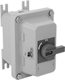
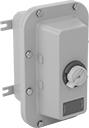
Powder-Coated Aluminum Housing—Made from aluminum, these switches also resist corrosion in wet or oily areas.
Lockout—Switches have a lockout, so you can secure them in the off position with a padlock (not included).
Hazardous Location Rating—They meet NEC Class I Div. 1 and 2, Groups B, C, D, and Class II, Div. 1 and 2, Groups E, F, and G.
Switching | |||||||||||||||
|---|---|---|---|---|---|---|---|---|---|---|---|---|---|---|---|
Style | Current, amp | Voltage, V AC | Switch Designation | Electrical Phase (hp) | Ht. | Wd. | For Max. Padlock Shackle Dia. | Wire Connection | Hazardous Location Rating | Enclosure Rating | Certification | Each | |||
Gray Powder-Coated Aluminum Housing with Red Actuator | |||||||||||||||
3 Circuits Controlled with Lockout | |||||||||||||||
| A | 30 | 600 | 3PST | Three (30 hp @ 600V AC) | 8 1/16" | 5 3/4" | 5/16" | Screw Terminal | NEC Class I Divisions 1, 2 Groups B, C, D NEC Class II Divisions 1, 2 Groups E, F, G NEC Zone 1 Groups IIB, IIA | NEMA 4X NEMA 7 NEMA 9 | CSA Certified, CSA-US Certified | 7857N11 | 000000000 | ||
Gray Powder-Coated Aluminum Housing with Yellow Actuator | |||||||||||||||
3 Circuits Controlled with Lockout | |||||||||||||||
| B | 60 | 600 | 3PST | Three (40 hp @ 600V AC) | 13 1/16" | 8 1/8" | 5/16" | Screw Terminal | NEC Class I Divisions 1, 2 Groups B, C, D NEC Class II Divisions 1, 2 Groups E, F, G NEC Zone 1 Groups IIB, IIA | NEMA 4X NEMA 7 NEMA 9 | CSA Certified, CSA-US Certified | 7857N12 | 00000000 | ||
| B | 100 | 600 | 3PST | Three (50 hp @ 600V AC) | 13 1/16" | 8 1/8" | 5/16" | Screw Terminal | NEC Class I Divisions 1, 2 Groups B, C, D NEC Class II Divisions 1, 2 Groups E, F, G NEC Zone 1 Groups IIB, IIA | NEMA 4X NEMA 7 NEMA 9 | CSA Certified, CSA-US Certified | 7857N13 | 00000000 | ||
Hazardous Location Differential Pressure Switches for Air
 |
With an explosion-proof enclosure that meets NEMA 7 and 9 standards for hazardous locations, these switches were tested and verified by UL for use where explosive gas or dust may be present. Often used with ovens, dryers, and HVAC systems, they can indicate a filter is clogged or help maintain a certain air pressure. These switches turn equipment on and off, activate automated controls, or signal alarms when the differential pressure reaches your setpoint. They are single pole, double throw (SPDT) and can be installed to turn one circuit from off to on or from on to off.
In addition to being UL listed, these switches are CE marked and FM approved, so they also meet European safety standards. They also are IP and NEMA rated for use outdoors and protect against dust and splashing water.
When measuring pressure in ductwork, pair them with a static pressure probe.
Pressure Set Point Range | Approx. Difference Between Set Point and Reset Point | Max. Input Pressure | Accuracy | Max. Switching Current @ Voltage | Process Temp. Range, ° F | Connection Material | For Use With | Enclosure Rating | Hazardous Location Rating | Each | |||
|---|---|---|---|---|---|---|---|---|---|---|---|---|---|
Screw-Terminal Wire Connection | |||||||||||||
1/8 NPT Female Pipe Connection | |||||||||||||
| 0.07 in. H₂O to 0.15 in. H₂O | 0.13 in. H₂O | 45 in. H₂O | ±2% | 15 amp @ 125V AC 15 amp @ 250V AC 15 amp @ 480V AC | -40 to 140 | Aluminum | Air | IP54, NEMA 3, NEMA 7, NEMA 9 | NEC Class I Divisions 1, 2 Groups C, D; NEC Class II Divisions 1, 2 Groups E, F, G | 5114N11 | 0000000 | ||
| 0.15 in. H₂O to 0.5 in. H₂O | 0.05 in. H₂O | 45 in. H₂O | ±2% | 15 amp @ 125V AC 15 amp @ 250V AC 15 amp @ 480V AC | -40 to 140 | Aluminum | Air | IP54, NEMA 3, NEMA 7, NEMA 9 | NEC Class I Divisions 1, 2 Groups C, D; NEC Class II Divisions 1, 2 Groups E, F, G | 5114N12 | 000000 | ||
| 0.4 in. H₂O to 1.6 in. H₂O | 0.18 in. H₂O | 45 in. H₂O | ±2% | 15 amp @ 125V AC 15 amp @ 250V AC 15 amp @ 480V AC | -40 to 140 | Aluminum | Air | IP54, NEMA 3, NEMA 7, NEMA 9 | NEC Class I Divisions 1, 2 Groups C, D; NEC Class II Divisions 1, 2 Groups E, F, G | 5114N13 | 000000 | ||
| 1.4 in. H₂O to 5.5 in. H₂O | 0.35 in. H₂O | 45 in. H₂O | ±2% | 15 amp @ 125V AC 15 amp @ 250V AC 15 amp @ 480V AC | -40 to 140 | Aluminum | Air | IP54, NEMA 3, NEMA 7, NEMA 9 | NEC Class I Divisions 1, 2 Groups C, D; NEC Class II Divisions 1, 2 Groups E, F, G | 5114N14 | 000000 | ||
| 3 in. H₂O to 11 in. H₂O | 0.45 in. H₂O | 45 in. H₂O | ±2% | 15 amp @ 125V AC 15 amp @ 250V AC 15 amp @ 480V AC | -40 to 140 | Aluminum | Air | IP54, NEMA 3, NEMA 7, NEMA 9 | NEC Class I Divisions 1, 2 Groups C, D; NEC Class II Divisions 1, 2 Groups E, F, G | 5114N15 | 000000 | ||
| 4 in. H₂O to 20 in. H₂O | 0.5 in. H₂O | 45 in. H₂O | ±2% | 15 amp @ 125V AC 15 amp @ 250V AC 15 amp @ 480V AC | -40 to 140 | Aluminum | Air | IP54, NEMA 3, NEMA 7, NEMA 9 | NEC Class I Divisions 1, 2 Groups C, D; NEC Class II Divisions 1, 2 Groups E, F, G | 5114N16 | 000000 | ||
| 0.5 psi to 2 psi | 0.3 psi | 35 psi | ±2% | 15 amp @ 125V AC 15 amp @ 250V AC 15 amp @ 480V AC | -40 to 140 | Aluminum | Air | IP54, NEMA 3, NEMA 7, NEMA 9 | NEC Class I Divisions 1, 2 Groups C, D; NEC Class II Divisions 1, 2 Groups E, F, G | 5114N17 | 000000 | ||
| 1.5 psi to 8 psi | 1 psi | 35 psi | ±2% | 15 amp @ 125V AC 15 amp @ 250V AC 15 amp @ 480V AC | 0 to 140 | Aluminum | Air | IP54, NEMA 3, NEMA 7, NEMA 9 | NEC Class I Divisions 1, 2 Groups C, D; NEC Class II Divisions 1, 2 Groups E, F, G | 5114N18 | 000000 | ||
| 3 psi to 15 psi | 0.9 psi | 35 psi | ±2% | 15 amp @ 125V AC 15 amp @ 250V AC 15 amp @ 480V AC | 0 to 140 | Aluminum | Air | IP54, NEMA 3, NEMA 7, NEMA 9 | NEC Class I Divisions 1, 2 Groups C, D; NEC Class II Divisions 1, 2 Groups E, F, G | 5114N19 | 000000 | ||
| 4 psi to 25 psi | 0.7 psi | 35 psi | ±2% | 15 amp @ 125V AC 15 amp @ 250V AC 15 amp @ 480V AC | 0 to 140 | Aluminum | Air | IP54, NEMA 3, NEMA 7, NEMA 9 | NEC Class I Divisions 1, 2 Groups C, D; NEC Class II Divisions 1, 2 Groups E, F, G | 5114N21 | 000000 | ||
| 15 psi to 50 psi | 1.25 psi | 70 psi | ±2% | 15 amp @ 125V AC 15 amp @ 250V AC 15 amp @ 480V AC | 0 to 140 | Aluminum | Air | IP54, NEMA 3, NEMA 7, NEMA 9 | NEC Class I Divisions 1, 2 Groups C, D; NEC Class II Divisions 1, 2 Groups E, F, G | 5114N22 | 000000 | ||
Hazardous Location Foot Switches
 |  |
With One Pedal | With Two Pedals |
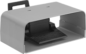
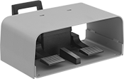
These switches are rated for environments where hazardous material is present. Press the pedal with your foot for hands-free operation. They have an oversized guard that accommodates bulky footwear.
Hazardous Location Rating—Hazardous location environmental ratings indicate whether manufacturers have included safety features in products to facilitate their safe use in a hazardous environment. Before selecting a product for a hazardous location, ensure it is rated for your environment.
Mounting | |||||||||||||
|---|---|---|---|---|---|---|---|---|---|---|---|---|---|
No. of Circuits Controlled | Switch Starting Position | Switch Action | Switch Designation | Switching Current @ Voltage | Fasteners Included | No. of Holes | Hole Dia. | Hazardous Location Rating | Enclosure Rating | Each | |||
1 Speed with Screw Terminal | |||||||||||||
Aluminum Housing with 1 Pedal, Oversized Guard, and Back Pivot | |||||||||||||
| 1 | 1 Off or 1 On | Momentary | SPDT | 20 amp @ 125V AC, 250V AC | No | 6 | 0.28" | NEC Class I Divisions 1, 2 Group D NEC Class II Divisions 1, 2 Groups F, G NEC Zone 1 Group IIA | IP41, NEMA 2, NEMA 7, NEMA 9 | 7480K21 | 0000000 | ||
| 2 | 2 Off or 2 On | Momentary | DPDT | 20 amp @ 125V AC, 250V AC | No | 6 | 0.28" | NEC Class I Divisions 1, 2 Group D NEC Class II Divisions 1, 2 Groups F, G NEC Zone 1 Group IIA | IP41, NEMA 2, NEMA 7, NEMA 9 | 7480K24 | 000000 | ||
Aluminum Housing with 2 Pedals, Oversized Guard, and Back Pivot | |||||||||||||
| 2 | 1 Off or 1 On | Momentary | SPDT | 20 amp @ 125V AC, 250V AC | No | 6 | 0.28" | NEC Class I Divisions 1, 2 Group D NEC Class II Divisions 1, 2 Groups F, G NEC Zone 1 Group IIA | IP41, NEMA 2, NEMA 7, NEMA 9 | 7480K22 | 000000 | ||
Hazardous Location Cable-Pull-Actuator Emergency Stop Switches
 |
Safe to use near ignitable gases and dust, the housing on these switches seals in anything that could ignite flammable material. All are UL listed and CSA certified for use in hazardous locations. Yank the cable anywhere along your line to quickly cut power in emergencies. They have positive-force, snap-open contacts that open a circuit when actuated, even if a spring fails or the contacts stick. The contacts will remain open until you tension the cable and reset the switch. Use the tension indicator to visually confirm that they’re reset correctly.
Mounting | ||||||||||||||||
|---|---|---|---|---|---|---|---|---|---|---|---|---|---|---|---|---|
For Max. Cable Lg., ft. | No. of Circuits Controlled | Switch Starting Position | No. of Terminals | Switch Designation | Switching Current @ Voltage | Max. Voltage | Actuation Force, lbf | Conduit Trade Size | Fasteners Included | Hole Dia. (No. of Holes) | Hole Thread Size (No. of Holes) | Features | Each | |||
Screw-Terminal Wire Connection | ||||||||||||||||
1 Direction (NEMA 4; NEMA 7; NEMA 9; NEMA 13; NEC Class I Divisions 1, 2 Groups B, C, D; NEC Class II Divisions 1, 2 Groups E, F, G) | ||||||||||||||||
| 200 | 1 | 1 Off or 1 On | 3 | SPDT | 10 amp @ 600V AC 10 amp @ 250V DC | 600V AC 250V DC | 25 | 1/2 | No | 1/4" (2) | 5/16"-18 (2) | Tension Indicator | 7543N11 | 000000000 | ||
| 200 | 2 | 2 On | 4 | DPST-NC | 10 amp @ 600V AC 10 amp @ 250V DC | 600V AC 250V DC | 25 | 1/2 | No | 1/4" (2) | 5/16"-18 (2) | Tension Indicator | 7543N12 | 00000000 | ||
Hazardous Location Differential Pressure Switches for Liquids
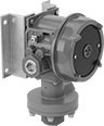 |
Tested and verified by UL and C-UL for use where explosive dust or gas are present, these switches have an explosion-proof enclosure that meets NEMA 7 and 9 standards for hazardous locations. They are often used to indicate a filter is clogged in a pump or cooling system. When the differential pressure reaches your setpoint, these switches can turn equipment on and off, activate automated controls, or signal alarms. They are single pole, double throw (SPDT) and can be installed to turn one circuit from off to on or from on to off.
In addition to being UL and C-UL listed, these switches are CE marked, so they also meet European safety standards. All switches are IP and NEMA rated for use outdoors and to protect against some corrosion, dust, and washdowns.
Pressure Set Point Range | Approx. Difference Between Set Point and Reset Point | Max. Input Pressure, psi | Accuracy | Max. Switching Current @ Voltage | Process Temp. Range, ° F | Connection Material | For Use With | Enclosure Rating | Hazardous Location Rating | Each | |||
|---|---|---|---|---|---|---|---|---|---|---|---|---|---|
Screw-Terminal Wire Connection | |||||||||||||
1/4 NPT Female Pipe Connection | |||||||||||||
| 5 in. H₂O to 80 in. H₂O | 2.5 in. H₂O | 225 | ±0.5% | 15 amp @ 125V AC 15 amp @ 250V AC 15 amp @ 480V AC 2 amp @ 30V DC 1 amp @ 48V DC 500 mA @ 125V DC | -10 to 200 | Aluminum | Diesel Fuel, Gasoline, Petroleum-Based Hydraulic Oil, Water | NEMA 4X, NEMA 7, NEMA 9, IP66 | NEC Class I Divisions 1, 2 Groups B, C, D; NEC Class II Divisions 1, 2 Groups E, F, G | 5214N11 | 0000000 | ||
| 2 psi to 20 psi | 0.2 psi | 225 | ±0.5% | 15 amp @ 125V AC 15 amp @ 250V AC 15 amp @ 480V AC 2 amp @ 30V DC 1 amp @ 48V DC 500 mA @ 125V DC | -10 to 200 | Aluminum | Diesel Fuel, Gasoline, Petroleum-Based Hydraulic Oil, Water | NEMA 4X, NEMA 7, NEMA 9, IP66 | NEC Class I Divisions 1, 2 Groups B, C, D; NEC Class II Divisions 1, 2 Groups E, F, G | 5214N12 | 000000 | ||
| 3 psi to 30 psi | 0.25 psi | 225 | ±0.5% | 15 amp @ 125V AC 15 amp @ 250V AC 15 amp @ 480V AC 2 amp @ 30V DC 1 amp @ 48V DC 500 mA @ 125V DC | -10 to 200 | Aluminum | Diesel Fuel, Gasoline, Petroleum-Based Hydraulic Oil, Water | NEMA 4X, NEMA 7, NEMA 9, IP66 | NEC Class I Divisions 1, 2 Groups B, C, D; NEC Class II Divisions 1, 2 Groups E, F, G | 5214N13 | 000000 | ||
| 10 psi to 100 psi | 0.6 psi | 225 | ±0.5% | 15 amp @ 125V AC 15 amp @ 250V AC 15 amp @ 480V AC 2 amp @ 30V DC 1 amp @ 48V DC 500 mA @ 125V DC | -10 to 200 | Aluminum | Diesel Fuel, Gasoline, Petroleum-Based Hydraulic Oil, Water | NEMA 4X, NEMA 7, NEMA 9, IP66 | NEC Class I Divisions 1, 2 Groups B, C, D; NEC Class II Divisions 1, 2 Groups E, F, G | 5214N14 | 000000 | ||
Remote-Sensing Hazardous Location Line-Voltage Thermostats
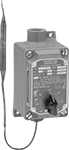 |
Place sensor in enclosures or different rooms than the rest of the thermostat to control temperature from outside the space. Use to regulate line-voltage HVAC systems where flammable gases, vapors, and dust are present.
Hazardous Location Rating—Thermostats are rated Class I, Divisions 1 and 2, Group D; and Class II, Divisions 1 and 2, Groups E, F, and G.
Overall | |||||||||||||||||||
|---|---|---|---|---|---|---|---|---|---|---|---|---|---|---|---|---|---|---|---|
Voltage, V AC | Current, amp | Temp. Setting, ° F | Switch Designation | Electrical Connection Type | Ht. | Wd. | Dp. | Sensor Cord Lg., ft. | For Use Outdoors | Mounting Fasteners Included | Mounting Hole Dia. | Display Type | Hazardous Location Rating | Enclosure Rating | Certification | Each | |||
For Air Conditioners and Heaters | |||||||||||||||||||
Dial Control | |||||||||||||||||||
| 120 to 277 | 22 | 20 to 80 | SPDT | Hardwire | 5 7/8" | 3" | 3 1/4" | 6 | No | No | 3/8" | Analog | NEC Class I Divisions 1, 2 Group D; NEC Class II Divisions 1, 2 Groups E, F, G | NEMA 7, NEMA 9 | CSA Certified, UL Listed | 1877K24 | 0000000 | ||
Hazardous Location Threaded Temperature Switches
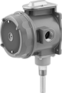 |
Often used in hazardous locations, such as chemical plants, refineries, and grain elevators, these switches have a housing that’s UL listed for environments with flammable gases, combustible dust, and ignitable fibers. It is UL listed for use in Class I, Divisions 1 and 2, Groups B, C, and D; Class II, Divisions 1 and 2, Groups E, F, and G; and Class III, Divisions 1 and 2 hazardous locations. The housing also meets NEMA 4X for use in washdown environments with splashing water, corrosive liquid, and dust. Install the threaded probe directly into tanks, pipelines, and other process components to turn heating equipment on or off at a specified temperature. Set actuation points with the adjustment dial.
1 Actuation Point—Switches with one actuation point have one SPDT (single pole, double throw) relay. The relay can be set to turn one circuit from off to on (normally open) or from on to off (normally closed).
2 Actuation Points—Switches with two actuation points have two SPDT (single pole, double throw) relays. Each relay can be set to turn one circuit from off to on (normally open) or from on to off (normally closed).
Probe | SPDT | |||||||||||||||||
|---|---|---|---|---|---|---|---|---|---|---|---|---|---|---|---|---|---|---|
Temp. Range, ° F | Temp. Accuracy | No. of Actuation Points | Actuation Tolerance | No. of Circuits Controlled | Max. Switching Current @ Voltage (Electrical Phase) | Dia. | Lg. | Max. Pressure, psi | Ht. | Wd. | Dp. | Enclosure Rating | Hazardous Location Rating | Certification | Each | |||
Threaded Brass Probe—1/2 NPT Male | ||||||||||||||||||
Adjustable Actuation Point | ||||||||||||||||||
| 0 to 225 | ±2° F | 1 | -1% to 1% | 1 | 15 amp @ 125V AC (Single) 15 amp @ 250V AC (Single) 15 amp @ 480V AC (Single) | 9/16" | 1 7/8" | 1,897 | 10" | 5 1/8" | 5 3/16" | IP66, NEMA 4X, NEMA 7, NEMA 9 | ATEX II 2 D Ex Tb IIIC T85° C Db ATEX II 2 G Ex Db IIC T6 Gb IEC Zone 1 Groups IIC, IIB, IIA IEC Zone 21 Groups IIIC, IIIB, IIIA IECEx Ex D IIC T6 Gb IECEx Ex Tb IIIC T85° C Db NEC Class I Divisions 1, 2 Groups B, C, D NEC Class II Divisions 1, 2 Groups E, F, G NEC Class III Divisions 1, 2 NEC Zone 1 Groups IIB, IIA | UL Listed, C-UL Listed, CE Marked | 5032K67 | 0000000 | ||
| 0 to 225 | ±2° F | 2 | -1% to 1% | 2 | 15 amp @ 125V AC (Single) 15 amp @ 250V AC (Single) 15 amp @ 480V AC (Single) | 9/16" | 1 7/8" | 1,784 | 10" | 5 1/8" | 5 3/16" | IP66, NEMA 4X, NEMA 7, NEMA 9 | ATEX II 2 D Ex Tb IIIC T85° C Db ATEX II 2 G Ex Db IIC T6 Gb IEC Zone 1 Groups IIC, IIB, IIA IEC Zone 21 Groups IIIC, IIIB, IIIA IECEx Ex D IIC T6 Gb IECEx Ex Tb IIIC T85° C Db NEC Class I Divisions 1, 2 Groups B, C, D NEC Class II Divisions 1, 2 Groups E, F, G NEC Class III Divisions 1, 2 NEC Zone 1 Groups IIB, IIA | UL Listed, C-UL Listed, CE Marked | 5032K87 | 00000000 | ||
Hazardous Location Wall-Mount Temperature Switches
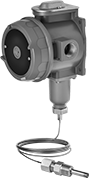 | 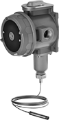 |
With Threaded Probe | With Unthreaded Probe |
Turn heating equipment on or off in environments with flammable gases, combustible dust, and ignitable fibers, such as chemical plants, refineries, and grain elevators. The switch housing is UL listed for use in Class I, Divisions 1 and 2, Groups B, C, and D; Class II, Divisions 1 and 2, Groups E, F, and G; and Class III, Divisions 1 and 2 hazardous locations. It also meets NEMA 4X for use in washdown environments with splashing water, corrosive liquid, and dust. Switches have a probe on a cable for remote temperature readings. Set actuation points with the adjustment dial.
1 Actuation Point—Switches with one actuation point have one SPDT (single pole, double throw) relay. The relay can be set to turn one circuit from off to on (normally open) or from on to off (normally closed). The probe has 1/2 NPT male threads for installation directly into tanks, pipelines, and other process components. It comes with a bushing that adapts the thread size to 3/4 NPT male.
2 Actuation Points—Switches with two actuation points have two SPDT (single pole, double throw) relays. Each relay can be set to turn one circuit from off to on (normally open) or from on to off (normally closed).
Probe | |||||||||||||||
|---|---|---|---|---|---|---|---|---|---|---|---|---|---|---|---|
Temp. Range | Temp. Accuracy | No. of Actuation Points | Max. Switching Current @ Voltage (Electrical Phase) | Dia. | Lg. | Ht. | Wd. | Dp. | Enclosure Rating | Hazardous Location Rating | Includes | Each | |||
SPDT—1 Circuit Controlled | |||||||||||||||
Threaded Stainless Steel Probe—1/2 NPT Male | |||||||||||||||
| 30° F to 250° F | ±5° F | 1 | 15 amp @ 125V AC (Single) 15 amp @ 250V AC (Single) 15 amp @ 480V AC (Single) | 3/8" | 2 5/8" | 9 5/16" | 5 1/8" | 5 3/16" | IP66, NEMA 4X, NEMA 7, NEMA 9 | ATEX II 2 D Ex Tb IIIC T85° C Db ATEX II 2 G Ex Db IIC T6 Gb IEC Zone 1 Groups IIC, IIB, IIA IEC Zone 21 Groups IIIC, IIIB, IIIA IECEx Ex D IIC T6 Gb IECEx Ex Tb IIIC T85° C Db NEC Class I Divisions 1, 2 Groups B, C, D NEC Class II Divisions 1, 2 Groups E, F, G NEC Class III Divisions 1, 2 NEC Zone 1 Groups IIB, IIA | 1/2 × 3/4 NPT Adapter Bushing | 5032K66 | 000000000 | ||
SPDT—2 Circuits Controlled | |||||||||||||||
Unthreaded Stainless Steel Probe | |||||||||||||||
| 30° F to 250° F | ±5° F | 2 | 15 amp @ 125V AC (Single) 15 amp @ 250V AC (Single) 15 amp @ 480V AC (Single) | 3/8" | 2 5/8" | 9 5/16" | 5 1/8" | 5 3/16" | IP66, NEMA 4X, NEMA 7, NEMA 9 | ATEX II 2 D Ex Tb IIIC T85° C Db ATEX II 2 G Ex Db IIC T6 Gb IEC Zone 1 Groups IIC, IIB, IIA IEC Zone 21 Groups IIIC, IIIB, IIIA IECEx Ex D IIC T6 Gb IECEx Ex Tb IIIC T85° C Db NEC Class I Divisions 1, 2 Groups B, C, D NEC Class II Divisions 1, 2 Groups E, F, G NEC Class III Divisions 1, 2 NEC Zone 1 Groups IIB, IIA | — | 5032K86 | 00000000 | ||
Hazardous Location Electrically Operated Air Directional Control Valves
Threaded Female Inlet × Threaded Female Outlet—Threaded Exhaust
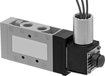 | 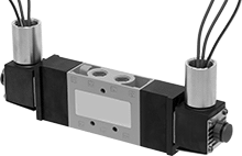 |
Single Solenoid | Double Solenoid |
5/3 (Closed Center) Flow Pattern—5/3 (closed center) valves close all ports in the off position to stop equipment in a locked position with air pressure holding it in place.
Flow Coefficient (Cv)—Flow coefficient (Cv) indicates how much airflow can pass through a valve.
Hazardous Location Rating—Hazardous location ratings indicate whether manufacturers have included safety features in products to facilitate their safe use in a hazardous environment. Before selecting a product for a hazardous location, ensure it is rated for your environment.
Overall | ||||||||||||||||||
|---|---|---|---|---|---|---|---|---|---|---|---|---|---|---|---|---|---|---|
No. of Flow Ports | Inlet Size | Outlet Size | Max. Flow Rate @ 100 psi, scfm | Flow Coefficient (Cv) | Pressure Range, psi | Vacuum Rating, in. Hg | Hazardous Location Rating | Enclosure Rating | Voltage | Wire Connection | Lg. | Wd. | Ht. | Mounting Fasteners Included | Each | |||
5/2 Flow Pattern | ||||||||||||||||||
Single Solenoid | ||||||||||||||||||
| 5 | 1/4 NPT | 1/4 NPT | 65.34 | 1.7 | 14 to 145 | 28 | NEC Class I Divisions 1, 2 Groups A, B, C, D NEC Class II Divisions 1, 2 Groups E, F, G | NEMA 3S NEMA 6P NEMA 7 NEMA 9 | 24V DC | Wire Leads | 6" | 1" | 2 7/8" | No | 2992N11 | 0000000 | ||
| 5 | 1/4 NPT | 1/4 NPT | 65.34 | 1.7 | 14 to 145 | 28 | NEC Class I Divisions 1, 2 Groups A, B, C, D NEC Class II Divisions 1, 2 Groups E, F, G | NEMA 3S NEMA 6P NEMA 7 NEMA 9 | 120V AC | Wire Leads | 6" | 1" | 2 7/8" | No | 2992N12 | 000000 | ||
5/3 (Closed Center) Flow Pattern | ||||||||||||||||||
Double Solenoid | ||||||||||||||||||
| 5 | 1/4 NPT | 1/4 NPT | 65.34 | 1.7 | 14 to 145 | 28 | NEC Class I Divisions 1, 2 Groups A, B, C, D NEC Class II Divisions 1, 2 Groups E, F, G | NEMA 3S NEMA 6P NEMA 7 NEMA 9 | 24V DC | Wire Leads | 9 3/8" | 1" | 2 7/8" | No | 2992N13 | 000000 | ||
| 5 | 1/4 NPT | 1/4 NPT | 65.34 | 1.7 | 14 to 145 | 28 | NEC Class I Divisions 1, 2 Groups A, B, C, D NEC Class II Divisions 1, 2 Groups E, F, G | NEMA 3S NEMA 6P NEMA 7 NEMA 9 | 120V AC | Wire Leads | 9 3/8" | 1" | 2 7/8" | No | 2992N14 | 000000 | ||
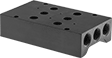 |
Manifolds are for single-solenoid, 24V DC valves.
No. of | Overall | |||||||||||||
|---|---|---|---|---|---|---|---|---|---|---|---|---|---|---|
Flow Ports | Inlet Ports | Exhaust Ports | Inlet Size | Exhaust Connection | Wd. | Ht. | Mount Type | Mounting Hole Dia. | Mounting Fasteners Included | Choose a Number of Stations | Each | |||
Manifold Style 4 | ||||||||||||||
| 6 | 2 | 4 | 3/8 NPTF | Threaded | 2 3/4" | 1 1/2" | Screw In | 0.16" | No | 2, 3, 4 | 6425K41 | 0000000 | ||
| 6 | 2 | 4 | 3/8 NPTF | Threaded | 2 3/4" | 1 1/2" | Screw In | 0.16" | No | 5, 6, 8 | 6425K42 | 000000 | ||
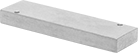 |
For Manifold Style | Body Material | Each | ||
|---|---|---|---|---|
| 4 | Aluminum | 6425K437 | 000000 |
